Multithreaded Virtual-Memory-Enabled Reconfigurable Hardware Accelerators Miljan Vuleti´c #1 , Paolo Ienne #2 , Christopher Claus ∗3 , and Walter Stechele ∗4 #
Processor Architecture Laboratory ´ Ecole Polytechnique F´ed´erale de Lausanne (EPFL) CH-1015 Lausanne, Switzerland 1
[email protected] 2
[email protected]
∗ Institute for Integrated Circuits Technische Universita¨ t M¨unchen Arcisstrasse 21, D-80290 M u¨ nchen, Germany 3
[email protected] [email protected]
4
Abstract— Although naturally belonging to the user process, hardware parts of codesigned reconfigurable applications execute outside of the operating system (OS) process: they have neither unified memory abstraction with software nor system services provided by the OS. This imposes limitations on hardware and software interfacing, narrows available programming paradigms, and affects application portability. Advanced programming concepts, such as multithreading, usually demand additional activities on the programmer side, to perform memory transfers and enforce memory consistency. In this paper, we introduce a system layer (an OS extension relying on a system hardware extension) that provides: (1) unified virtual memory, (2) platform-agnostic interfacing, and (3) multithreaded execution, for hardware accelerators running within the same OS process with user software. The system layer releases software programmer and hardware designer from interfacing burdens and, still, achieves significant speedups over software with only limited overheads. Virtualmemory-enabled hardware accelerators benefit from all abstractions and services already available to software. To prove our concept in practice and demonstrate the ease of programming, we execute image processing and cryptography applications on reconfigurable systems-on-chip running GNU/Linux that supports virtual memory for multithreaded hardware accelerators.
I. I NTRODUCTION User programs are rarely run bare on the underlying system hardware. An abstraction layer created through system software (e.g., an Operating System—OS) provides the execution environment, eases programming, increases portability, improves security, and releases programmers from managing and sharing hardware resources (i.e., processors, memories, storage devices, I/O peripherals). There is no such support for user hardware. In this paper, we describe the actions we take for bringing the benefits of the OS abstractions to user hardware as well. A. Codesigned Applications in Software-centric Systems We call codesigned hardware and software applications those applications that have some of their parts running on CPUs and the rest running in specialised hardware (i.e., hardware specifically designed to speed up and parallelise the
0-7803-9729-0/06/$20.00 2006 IEEE
execution of some performance demanding tasks). Codesigned applications mix two approaches of computation [1], [2]: (1) temporal computation (scarce hardware resources such as ALUs, shifters, multipliers are reused in time by the instruction sequence being executed), and (2) spatial computation (abundant hardware resources are wired and deployed in space— silicon area—to fit more closely the nature of the application, thus maximising the processing parallelism). In codesigned and reconfigurable applications, the user-level application code (program text) is not monolith but heterogeneous. The code consists of (1) software parts (sequences of machine instructions typically generated by a compiler from a text written in a high-level programming language) and (2) hardware parts (hardwired or configurable networks of logic gates typically generated by a synthesiser from a text written in a hardware description language). Semantically, the software and hardware parts of a program represent a unified entity since they exhibit jointly some specified functionality and operate on the same data. However, the abstraction provided by the system to software and hardware parts of user applications is very different—user software does not recognise user hardware as its peer. The Y-chart in Figure 1 shows the different levels of abstraction—provided and managed by the OS—visible to software and hardware parts of a codesigned application running in a software-centric system. Each software-only application enjoys the perfect memory abstraction through the virtual memory support of system software and system hardware. Through the interface of system calls, system hardware is completely abstracted, hidden, and protected by the OS. However, these abstractions do not hold for codesigned applications: (1) user software and user hardware (as shown in Figure 1) do not share the memory address space—it is typically on the application programmer and designer to arrange the communication and data transfers; (2) system services are only partially available to user hardware—although programmers may use software wrappers to call system services on behalf of the
197
FPT 2006
User SW
User HW
User HW
User SW
Memory Abstraction
Memory Abstraction
System SW
System SW
System HW
System HW Full Support Partial Support
OS View OS View
Fig. 1. Levels of abstraction for codesigned applications in a softwarecentric system. User hardware lacks the abstractions usually available to user software.
Fig. 2. User software and user hardware as peers in a system supporting codesigned applications: both user software and user hardware have the same abstractions available.
C. Paper Organisation user hardware, it is difficult (or even impossible) for the user hardware to use the result of a system service if there is no memory abstraction present (as an example, think of dynamic memory allocation); (3) for hardware-only applications (that would not use CPU at all—at least at the user level—but only the hardwired logic) there is neither memory abstraction nor system call support altogether. Advanced programming concepts, such as multithreading, usually demand additional activities on the programmer side to perform memory transfers and enforce memory consistency. Not only programming transparency, but also portability of such applications across different platforms is affected.
We show our motivation and discuss in more detail our proposal in Section II. In Section III and Section IV, we present the hardware and software architectures of our solution for virtual memory management of multithreaded reconfigurable applications. We demonstrate our system in practice in Section V. In Section VI, we present related work. Finally, we conclude in Section VII.
B. Our Contribution
A. Typical Architectures and Their Programming
Our goal is to provide the missing abstractions and bring user software and user hardware to the same conceptual level. For this purpose, we propose a unified OS process context for heterogeneous-code programs. We delegate platform-specific tasks to a system-level virtualisation layer, which allows us to achieve seamless integration of software and hardware and to increase the portability of codesigned applications. The delegation of system specific tasks to the OS makes possible extending the incomplete or missing abstraction layers from Figure 1 to the full boxes in Figure 2 and simplifies enabling simultaneous execution of user hardware and user software within the same process. Starting from a simple idea of unified virtual memory for software and hardware parts of codesigned reconfigurable applications, we contribute to the research community with the first general evaluation of this concept in practice, on real reconfigurable systems. We show that—even with the overheads of our mixed software-and-hardware approach—having virtual-memory-enabled hardware accelerators is beneficial, in the terms of simplified HW/SW interfacing and performance. When building future systems for codesigned applications, designers can immediately rely on (1) our results and (2) our overhead analysis.
Figure 3 shows a hardware accelerator (user hardware) directly accessing a local on-chip memory to perform the computation. The user software, running on the CPU, has a perfect, linear image of the memory provided by Memory Management Unit (MMU) and the virtual memory manager of the OS. On the contrary, the user hardware is directly interfaced to the system hardware and generates physical memory addresses for fast accessing of the local memory. The programmer controls the accelerator and accesses its local memory through a memory mapped region. If the memory size is limited, the programmer is responsible for partitioning data and scheduling data transfers. Figure 4 compares programming of the IDEA cryptography application for its pure software and codesigned implementation. The software-only version just invokes the encryption function by passing the pointers to the input and output IDEA blocks. On the other side, using the hardware accelerator demands partitioning the data to fit the local memory, transferring the data explicitly, and iterating until the computation is finished. Although it is not a difficult task, it is quite burdensome and demands programmer’s knowledge of the hardware memory access pattern. In principle, the local memory serves as a software managed cache or scratchpad.
II. M OTIVATION Software programmers and hardware designers have to solve the interfacing for a particular architecture they use. In this section, we show some typical solutions for solving the interfacing problem.
198
Master
Master
CPU
CPU Main Memory
Main Memory
MMU
MMU
Cache
Cache System Bus
Local Memory
Hardware Accelerator
System Bus
Slave
Hardware Accelerator
Working Memory
Working Memory
FPGA or ASIC
Fig. 3.
Master/Slave
FPGA or ASIC
Typical hardware accelerator accessing local memory.
Fig. 5.
Typical hardware accelerator accessing main memory.
/* Pure software version, IDEA cryptography */ idea block A[n64], B[n64]; ... idea cipher sw (A, B, n64); -------------------------------------------------------------
/* Pure software version */ unsigned char outimg[imgsize], inpimg[4][imgsize]; ... contrast enhancement sw (outimg, inpimg, winsize, imgsize); -------------------------------------------------------------
/* Typical HW accelerator version accessing local memory */ idea block *buff = mmap(0, sizeof(idea block), LBUFF PHYADDR); ... data chunk = LBUFF SIZE / 2; data ptr = 0; while (data ptr < n64 * sizeof(idea block)) { memcpy (buff, A + data ptr, data chunk); *IDEA CTRL REG = START; while(*IDEA STATUS REG != FINISH); *IDEA STATUS REG = INIT; memcpy (B + data pt, buff + data chunk, data chunk); data ptr += data chunk; }
/* Typical HW accelerator version accessing main memory */ unsigned char *resimg = mmap(0, imgsize, RES PHYADDR); unsigned char *inpimg[i] = mmap(0, winsize,INPi PHYADDR); ... memcpy (inpimg[i], camera out[frame i], winsize); *CONTRAST CTRL REG = START; while(*CONTRAST STATUS REG != FINISH); *CONTRAST STATUS REG = INIT; memcpy (outimg, resimg, winsize);
Fig. 4. Programming for the IDEA application: pure SW version (top) and typical HW accelerator version accessing local memory (bottom).
Figure 5 shows another approach with a hardware accelerator capable of initiating master transactions on the system bus and directly accessing the main memory. The user software is responsible for controlling the accelerator and passing the physical addresses of a fixed memory region, previously reserved by the OS. As user hardware generates physical addresses of the main memory, an erroneous accelerator may cause nondeterministic behaviour of the whole system. With assumption that a large amount of the physical memory is available (which may not be always true, especially in the embedded applications), the programming is made simpler (as shown in Figure 6 for an image processing application): there is no need to partition and copy data iteratively. However, single accesses to the main memory are rather expensive. To overcome this, the hardware designer has to manage and implement burst accesses to the main memory, which imposes creating buffers and local memory management on the hardware side: the programmer’s burden from Figure 4 has not disappeared but is just shifted to the hardware designer. In the case of the contrast enhancement application (used later in our experiments of Section V), the hardware designer would have to manage four input and one output data buffers filled and emptied by burst transfers, and synchronise them with the accelerator.
Fig. 6. Programming for the contrast enhancement application: pure software version (top) and typical HW accelerator version accessing main memory (bottom).
Figure 7 sketches possible execution timelines of the two typical approaches. The overall Execution Time (ET ) of the approach with the local memory is the sum of the Copy Time (CT ) and pure Hardware execution Time (HT ). The overall execution time (ET ) of the approach with the main memory consists of hardware executions interleaved (or partially overlapped if bursts are supported) with master memory accesses. If we assume identical computation cores of accelerators, their pure HT times are the same: the overall performance depends on the effectiveness of memory transfers. It is debatable which of the two approaches is better: a programmer responsible for data transfers to the local memory can overlap computation with data transfers (by dividing the local memory in two halves—the first processed by the hardware and the second used for copying) or use a DMA (although this would mean descending from the user-level to system programming) to speed up the process; a hardware designer responsible for memory accesses to the main memory can use burst accesses and hardware managed buffers to improve the performance. What is clear is that in both cases the user-level software and hardware are burdened with the kind of tasks that are usually delegated to the system: pushing the management of the virtual memory hierarchy from the programmer on the virtual memory manager is a common solution to an analogous problem in general-purpose computer architecture.
199
Hardware Accelerator Accessing Local Memory Wait
User SW CT(in)
Wait
CT(out) CT(in)
HT
User HW
CT(out) CT(in)
HT
...
portable
CT(out)
Copy Time
Hardware Time
?
HW Accelerator
... ...
User HW
virt_addr cp_din cp_dout cp_be
A R
cp_ctrl
XCHNG RegFile
Prefetch Support
CR
SR
TLB
DMA
...
toward the system bus
User SW ET
start
platform-specific phy_addr cp_din Dual-ported Local cp_dout Memory cp_be
WMU
HT
...
...
ASIC
FPGA Wait
end
Hardware Accelerator Accessing Main Memory
Fig. 7. Execution timelines of typical hardware accelerators. Assuming identical computation cores, the overall performance depends on the effectiveness of memory transfers.
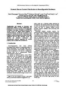
Fig. 9. WMU structure and interfaces to user hardware, local memory, and system.
details of our architecture, illustrate its benefits, and show that performance is not dramatically affected, despite of the inherent overhead of this scheme.
Master CPU Main Memory MMU
III. H ARDWARE A RCHITECTURE The translation from virtual to physical addresses is enabled by: (1) Memory Management Unit (MMU) in the CPU case, and (2) user hardWare memory Management Unit (WMU) in the accelerator case. Apart the virtual address translation, the WMU also defines a standardised hardware interface for hardware accelerators, enables parameter exchange between software and hardware, and provides a way for user hardware to call back software functions.
Cache System Bus Local Memory
WMU
Local Memory
...
WMU
Mem.Coh Bus Arbiter Mem.Coh. Bus
Hardware Accelerator
...
Hardware Accelerator FPGA or ASIC
A. WMU Interface
Fig. 8. Multithreaded hardware accelerators capable of accessing virtual memory of user process through user hardWare memory Management Units (WMUs), in a similar way as user software does through MMUs.
B. Virtual-memory-enabled Hardware Accelerators To enable transparent memory transfers and screen user software and user hardware from the interfacing burden, we propose using hardware accelerators capable of accessing virtual memory and sharing the address space with software. Figure 8 shows an architecture that allows multiple application-specific hardware accelerators to run in the process context of their peer software. Not only that it can simplify hardware/software interfacing but it can allow hardware accelerators to benefit (transparently and without any need for user intervention) from spatial and temporal locality of memory accesses— a well-known and largely-exploited concept from generalpurpose computing. To achieve this goal, we need: (1) system hardware support for user hardware invocation, virtual address translation, and memory coherency, and (2) system software support for steering these activities and enabling the inter operation with user software. We chose a mixed software and hardware scheme that only slightly trades off performance for applicability to a wide range of (reconfigurable) SoCs: there are no requirements regarding the system-bus capability to support memory coherence protocols. In the following sections, we present
Figure 9 shows a detailed structure of the WMU, with its interfaces toward the hardware accelerator and toward the rest of the system. The WMU translates virtual addresses demanded by the accelerator (similarly as the MMU does for user software) to real addresses of the local memory divided into pages. If a page is not present, the WMU generates an interrupt to request the OS handling and stalls the hardware accelerator (as the CPU may be stalled on a cache miss). The central component of the WMU is a Translation Lookaside Buffer (TLB), a standard component in general-purpose CPUs to speed up address translation. Apart from the usual control and status registers (CR, SR), there is an exchange register file (for passing parameters between software and hardware, and vice versa), prefetching support logic, and the address register containing a faulty address—this register is examined by the OS, in order to find a missing page in the main memory. The OS either performs the page transfer or uses a DMAfor this task. B. Multithreading Support Having multiple virtual-memory-enabled hardware accelerators that work in parallel may violate data integrity. To enable our hardware accelerators to share the coherent memory and to enforce strict memory consistency, we extend the basic WMUs with a simple, invalidation-based, mixed hardwareand-software coherency protocol [3].
200
/* Virtual memory-enabled accelerator version */ void idea cipher cp(IDEA block *A, IDEA block *B, int n64) { param.params no = 3; param.flags = 0; param.p[0] = A; param.p[1] = B; param.p[2] = n64; FPGA EXECUTE (IDEA HW, ¶m); }
Invalidate WMU
Invalid HWAcc Read/Write OS/Copy In
HWAcc Read/Write OS/Copy In Read/Write Fault OS
Shared
Fig. 10. Library function for calling the IDEA hardware accelerator in our system. Calling this function is to all practical purposes identical to the pure software version and fully system-detail agnostic. The hardware accelerator receives virtual memory pointers to the data to process.
Read/Write Fault OS
Exclusive
HWAcc Read
HWAcc Read Read/Write Fault OS/Write Back HWAcc Write WMU/Invalidate
HWAcc Write WMU
Modified
Stimulus
Figure 8 shows multiple WMUs connected to an internal, custom bus, separated from the system one. An arbiter accessible and controllable by the OS through the system bus is also connected to memory coherence bus. Each WMU keeps track of states for the pages residing in the local memory and snoops on the coherence bus (the protocol diagram is shown in Figure 11). The OS-prevailing management for page-level coherency can definitely have negative performance impacts, but in the absence of heavy data sharing may be sufficient. If the system bus supported the coherency for hardware accelerators, our solution could imply less OS involvement and provide finer granularity than the page-level one.
Responsible/Bus Action
HWAcc Read/Write
Fig. 11. State diagram for page-level memory coherence protocol: OS (software) and WMU (hardware) actions.
the page is dirty, the OS copies its contents back to the userspace memory and the allocates the page for the missing data; then, the OS transfers the missing data page from the userspace memory and updates the WMU state; afterward, the OS allows the WMU to restart translation and lets the accelerator exit from the stalled state.
IV. OS E XTENSIONS We extend the OS with a virtual memory manager for hardware accelerators. It provides a standardised system services to user software and manages the translation performed by the WMU, similarly as the OS does with MMU. A. Basic Architecture The manager provides two functionalities: (1) a system call to access and control the accelerator, and (2) management functions to respond to WMU requests. The system call provided to software designers is called FPGA_EXECUTE. It passes data pointers or other parameters to the hardware, initialises the WMU, launches the accelerator, and blocks the calling thread, while not affecting the remaining SW threads that execute in parallel. The accelerator processes the data with no concerns about their location in memory—the WMU translates generated addresses. Figure 10 shows the system call in practice, for the IDEA application. The local memory is logically organised in pages, as in typical virtual memory systems. Data accessed by the accelerator are mapped to these pages. The accelerator can address any word of the user address space. However, having the accesses go through the OS manager, memory protection policies can be easily achieved (e.g., preventing the accelerator to access forbidden memory regions). The OS keeps track of the occupied pages and their state. The WMU signals a page fault if the accelerator attempted to access an address not currently in the local memory. The OS rearranges the current mapping to the local memory in order to resolve the fault. It may happen that all pages are in use; then, a page is selected for eviction (different replacement policies are possible). If
B. Supporting Multiple Hardware Accelerators In the case of multiple hardware accelerators executing in parallel, the manager keeps track of all their translation data structures, manages the translation, and implements a coherence protocol. On a page fault, the manager checks is the page already present in any local memory. If true, for example, it changes the WMU state of the page to SHARED and fulfills the fault request by copying the data to the local memory of the accelerator missing the page. In the same fashion, the OS activities follow the memory coherency state transition diagram, showed in Figure 11. As it services multiple WMUs, it can be a potential bottleneck. For the moment, we use only applications with a couple of hardware accelerators. Apart from supporting multiple accelerators (each having a single memory port), the manager can provide multiple memory ports to a single hardware accelerator [4]; the applications that need multiple paths to memory may benefit from this capability. V. E XPERIMENTAL R ESULTS We have implemented the virtual memory manager for hardware accelerators as an extension of the Linux/GNU OS running on two different reconfigurable SoC platforms (one based on an Altera Excalibur device—EPXA1 containing an ARM processor running at 133MHz—and the other on a Xilinx Virtex-II Pro—XC2VP30 containing a PowerPC processor running at 300MHz). We have designed the WMU in VHDL and ported it to both platforms. The OS module and the WMU support different local memory and page sizes. We have measured several single hardware accelerators applications and a multithreaded image processing application.
201
RT OS
page start
ST
MT CT1 MT
Exec - HT1
User HW
Wait
pos(x0,y0) memory area transfered by the OS but not used by the accelerator
...
MT CT2 MT Exec - HT2
page end
...
page border
(a) No Prefetching
User HW
MT CT1 MT
MT CT2 MT
MT CT3 MT
Exec - HT1
Exec - HT2
...
RT ST
MT CT4 MT ... Exec - HT3
...
win.x
win.y
OS
RT ST
img.y
RT
processing window
img.x, img.y - image size img.x
win.x, win.y - window size
(b) Prefetching
Fig. 12. The OS activities related to User HW execution. The OS manages translation data structures (Management Time—MT) and copies pages from/to the user memory (Copy Time—CT). When finished, it invokes schedule() and sleeps (Sleep Time—ST). The hardware accelerator executes (Hardware Time—HT) until it finishes or tries accessing a page not present in the local memory. In both cases, it waits for the OS action. The OS responds after some time (Response Time—RT). Instead of sleeping, the OS can fetch in advance pages that may be used by the accelerator. This results in uninterrupted hardware execution.
Compared to classic approaches, there are several sources of overhead in our scheme [4]. The first one is due to the virtual address translation: limitations of the FPGA technology and design methodologies different than those of ASICs result in a TLB which performs the translation in multiple clock cycles (4–6 in our implementations). Thus, the Hardware execution Time (HT ) of virtual-memory-enabled accelerators is longer than in the case of accessing the local memory by physical addressing: HT (virtual) = t × HT (typical), where t > 1 is the translation overhead, proportional to the number of memory accesses. It would be practically one, if the WMUs were standard parts implemented in ASIC. Figure 12a shows different time components during the execution of a hardware accelerator. Having the OS responsible for the translation management brings Manage Time (M T ) and Response Time (RT ) as inherent overheads to the performance equation. Sleep Time (ST = HT (virtual) + RT ) represents the time of the OS idleness, with respect to its actions on behalf of the accelerator. If we assume the same data transfer technique employed for a virtual-memory-enabled accelerator and a typical one, the overall execution time (ET ) of the virtual-memory-enabled accelerator is: ET (virtual) = t × HT (typical) + c × CT (typical) + RT + M T , where c > 1 is the page-level granularity overhead. As shown in Figure 13, in contrast to typical approaches, not necessarily all of the transferred data are used by the accelerator. The effect is wellknown and studied in the OS and cache theories. To address this, our WMU implementation and the OS extension support different number of pages and sizes of the local memory. Despite the incurred overhead, the involvement of system software in execution steering allows dynamic optimisations that can improve the performance. As Figure 12b shows, instead of being idle, the OS can (with a lightweight hardware support in the WMU to detect coprocessors memory access patterns) monitor the execution, predict future memory accesses, and perform memory prefetching accordingly. For the moment we use a simple, software-managed and hardware-
supported, stream buffer-based technique [5], [6] that is completely transparent to the user. B. Performance and Transparency Figure 14 shows execution times for the IDEA cryptography application running on the two different platforms (both with the local memory of 16KB). Our intention is not to compare the platforms, but to emphasize that virtual-memory-enabled hardware accelerators can achieve significant performance advantage over the pure software, and have the performance comparable to the typical solution described in Section II-A, Figures 3 and 4). To run experiments on the two different platforms, we had to port the WMU hardware and to adapt the Linux OS module, but there was no need to do any changes to the accelerator HDL nor to the application C code. To get the application running, it was sufficient just to recompile and resynthesise its code. Figure 15 and Figure 16 show executions times of two image processing applications (contrast enhancement and edge detection). The applications use accelerators directly accessing the main memory (as explained in Section II-A). In the case of virtual-memory-based accelerators, we use the local memory of 64KB organised into 8 or 16 pages. The OS module uses a DMA to transfer the pages to the local memory: the end user benefits of the improved performance but is completely screened of the enhanced system-level support. The typical accelerator in Figure 15 does not implement burst accesses to the memory (recall to Figure 7) which affects it performance: despite the page-level granularity overhead, the virtual-memory-enabled accelerators outperform the typical IDEA Execution Times for Different Platform Types (128KB Input Data Size) 60
no prefetching prefetching
50
Pure SW
40
MT
30
ST
20
CT
277.17ms
ms
A. Overhead Analysis
Fig. 13. Memory layout of an image. Processing a window region smaller than the image size imposes the copying overhead due to the page-granularity.
typical
125.17ms
10 0 ARM
Altera
Altera-NP Altera-P PowerPC
Xilinx
Xilinx-NP
Xilinx-P
Platform Type
Fig. 14. Two platforms (based on Altera or Xilinx devices) run the same application. Results are shown for pure software (ARM, PowerPC), typical (Altera, Xilinx), and virtual-memory-enabled accelerators, without ({Altera,Xilinx}-NP) and with prefetching ({Altera,Xilinx}-P) in the OS.
202
Contrast Enhancement in SW and HW 80 70
Local memory 16 pages (no prefetching) Local memory 16 pages (with prefetching)
60
ms
50
Contrast Engine
Camera Capture
Local memory 8 pages (no prefetching)
138.3ms
Edge Engine
HW
SW
HW
40 30 Pure SW Typical HW
20 MT ST CT
10 0
160x120
320x240
}
Virtual Memory
Virtual HW
Fig. 17. Multithreaded edge detection. Producer/consumer chain of threads synchronised by software semaphores.
512x512
Window Size
Fig. 15. Execution times of contrast-enhancement application implemented with pure software, typical hardware, and virtual memory-enabled hardware. Edge Detection in SW and HW 30
56.8ms
25 Local memory 8 pages (no prefetching)
ms
20
Local memory 8 pages (with prefetching)
15 10 Pure SW Typical HW
5 0
MT ST CT 160x120
320x240
}
Virtual HW
500x500
Window Size
Fig. 16. Execution times of edge-detection application implemented with pure software, typical hardware, and virtual-memory-enabled hardware.
solution. More importantly, the benefit comes for free for the hardware designer: there is no need to implement and manage bursts. The typical accelerator in Figure 16 implements burst accesses to the memory and locally caches the transfered data. It is significantly faster than the virtual-memory-enabled accelerators for the smallest window size but, for larger window sizes, the two approaches achieve closer performance. Since the WMU memory interface is simpler (no burst and no pipelining support), it provides an easy way—the system now takes care of the data transfers—for a designer to get results comparable with typical approaches.
our hardware memory pointers obtained by the malloc() function call; there is no need for software wrappers responsible for memory transfers. Our approach can process more than 50 image windows per second with a large safety margin—other applications can run in the system. Our approach outperforms the typical solution and, even more remarkably, this benefit comes along with our simple and transparent design paradigm. The execution time of the typical solution is dominated by slower contrast-detection accelerator and, the lack of local memories also degrades the performance by increasing the bus contention. Our virtualisation layer hides from designers relatively complex design issues of burst accesses and local memory management (either in software or hardware) and, still, may offer better performance. D. Area Overhead Although the Altera device that we use is the smallest in its family, the WMU area overhead is acceptable (not more than one fifth of the EPXA1 resources). In the case of the Xilinx device, the overhead per WMU is even smaller, with respect to the larger programmable area available on the chip. VI. R ELATED W ORK In the field of reconfigurable computing, different researchers [7], [8] have considered using the OS to manage FPGA resources (i.e., reconfigurable chip area used for executing different coprocessors); on our side, we use the OS to provide transparent interfacing, unified memory address space and to Pure SW and HW/SW Multithreaded Execution
C. Multithreaded HW Execution
1543ms
1000
Pure SW Typical HW/SW Virtual HW/SW
800
600
ms
We use a multithreaded image processing application to demonstrate our virtual memory manager supporting simultaneous execution of multiple hardware accelerators. We setup the application threads (shown in Figure 17) in a producer/consumer chain that allows the contrast and edge detection accelerators to work in parallel, on different image windows slided in time. We compare the results obtained for software-only version of the application and the codesigned applications with typical or virtual-memory-enabled accelerators. Apart from the significant performance improvement obtained by our approach, we stress the programming simplicity: our threads operate on images stored on the heap, we pass to
3075ms 1036ms
400
200
0 1
5
10
25
50
Number of 320x240 Windows
Fig. 18. Execution times for multithreaded versions of SW-only, typical, and virtual-memory-based codesigned HW/SW applications.
203
enforce memory consistency between software and reconfigurable hardware running in the context of an OS process. The two concepts are orthogonal and complementary: future systems may have to implement both. An advanced OS-based solution [9] introduces a Hardware Abstraction Layer (HAL) responsible for communication between software and hardware. Similarly to our virtualisation layer, the HAL consists of software and hardware components but, it assumes a specific communication scheme based on message passing. An industrial solution [10] introduces software (C language) and hardware (Handel-C language) API supported by an intermediate system layer—Data Streaming Manager (DSM)—providing platform-independent and stream-based communication. Our scheme assumes no specific API but allows both user software and multiple hardware accelerators—being within the context of the same OS process—to share any location of the practically-unlimited virtual memory. Another industrial solution [11] has recently employed HyperTransport [12], which is a noncoherent interconnection standard for processors and peripherals, for providing a close connection of an FPGA module with the CPU. Plugging the module into a HyperTransport socket enables hardware accelerators implemented in the FPGA to directly access the main system memory. In contrast to our approach, the solution demands user-space applications to use memory maps and to manage the memory explicitly. Some researchers [13] have considered system peripherals (like network interfaces) capable of accessing virtual memory, in order to improve performance of application-specific communication. We extend this approach, by proposing a general scheme that distinguishes user hardware (having explicit semantical links with a particular user application) from system hardware (such as mass storage, network interfaces, reconfigurable logic, being implicitly available to all user applications). Different research groups have developed models of parallel execution for reconfigurable computing systems [2]. Some authors [14], for example, have proposed a hardware-centric parallel programming model targeting mainly the design of networking applications. Other authors [15], [16], in a work closer to ours, have investigated system support for multithreaded reconfigurable applications; however, they concentrate on efficient implementation in hardware of thread synchronisation primitives and rapid scheduling support. On our side, we concentrate on the unified memory space and seamless integration of SW and HW, thus the two approaches are complementary. Finally, a previous work [17] have introduced virtual memory for hardware accelerators but with limitations on parallel execution that we overcome in this paper. VII. C ONCLUSIONS Our work is a first attempt to put hardware and software threads on an equal standing. Within the context of the unified OS process—for user software and user hardware—we provide means for simultaneous execution and seamless interfacing of software and hardware threads. We have proved with examples
on two real platforms that our approach offers straightforward programming and hardware design of multithreaded codesigned applications for an affordable cost. Future work should address minimising the performance overheads and exploring possibilities of runtime dynamic optimisations for applications with different memory access patterns. ACKNOWLEDGEMENTS We acknowledge the help and support provided by Ingmar Cramm, Sven Gowal, Chidamber Kulkarni, Florian Mueller, Taranbir Singh, Jian Wang and the Xilinx University Program. R EFERENCES [1] A. DeHon, “The density advantage of configurable computing,” Computer, vol. 33, no. 4, pp. 41–49, Apr. 2000. [2] M. Gokhale and P. S. Graham, Reconfigurable Computing: Accelerating Computation with Field-Programmable Gate Arrays. Berlin: Springer, 2005. [3] J. Proti´c, M. Tomasevi´c, and V. Milutinovi´c, Eds., Distributed Shared Memory: Concepts and Systems. Los Alamitos, Calif.: IEEE Computer Society Press, 1997. [4] M. Vuleti´c, “Unifying software and hardware of multithreaded reconfigurable applications within operating system processes,” Ph.D. Thesis ´ no. 3626, Ecole Polytechnique F´ed´erale de Lausanne, Lausanne, 2006. [5] N. P. Jouppi, “Improving direct-mapped cache performance by the addition of a small fully-associative cache and prefetch buffers,” in Proceedings of the 17th Annual International Symposium on Computer Architecture, Seattle, Wash., May 1990, pp. 364–73. [6] S. Palacharla and R. E. Kessler, “Evaluating stream buffers as a secondary cache replacement,” in Proceedings of the 21st Annual International Symposium on Computer Architecture, Chicago, Ill., Apr. 1994, pp. 24–33. [7] H. Walder and M. Platzner, “Online scheduling for block-partitioned reconfigurable devices,” in Proceedings of the Design, Automation and Test in Europe Conference and Exhibition, Munich, Mar. 2003, pp. 10 290–95. [8] M. Dales, “Managing a reconfigurable processor in a general purpose workstation environment,” in Proceedings of the Design, Automation and Test in Europe Conference and Exhibition, Munich, Mar. 2003, pp. 10 980–85. [9] V. Nollet, P. Coene, D. Verkest, S. Vernalde, and R. Lauwereins, “Designing an operating system for a heterogeneous reconfigurable SoC,” in Reconfigurable Architectures Workshop (RAW), Proceedings of the International Parallel and Distributed Processing Symposium, Paris, June 2003. [10] C. Sullivan and M. Saini, “Software-compiled system design optimizes Xilinx programmable systems,” Xcell Journal, no. 46, pp. 32–37, Summer 2003. [11] “XD1000 FPGA coprocessor module for socket 940,” http://www.xtremedatainc.com/, 2006, XtremeData Inc. [12] HyperTransport 3.0 Specification, http://www.hypertransport.org, HyperTransport Consortium, 2006. [13] S. S. Mukherjee and M. D. Hill, “Making network interfaces less peripheral,” Computer, vol. 31, no. 10, pp. 70–6, Oct. 1998. [14] G. Brebner, P. James-Roxby, and C. Kulkarni, “Hyper-programmable architecture for adaptable networked systems,” in Proceedings of the 15th International Conference on Application-specific Systems, Architectures and Processors, Galveston, Tex., Sept. 2004, pp. 328–38. [15] D. Andrews, D. Niehaus, R. Jidin, M. Finley, W. Peck, M. Frisbie, J. Ortiz, and E. Komp, “Programming models for hyprid FPGA-CPU computational components: A missing link,” IEEE Micro, vol. 24, no. 4, pp. 42–53, July 2004. [16] E. Anderson, J. Agron, W. Peck, J. Stevens, F. Baijot, E. Komp, and D. Andrews, “Enabling a uniform programming model across the software/hardware boundary,” in Proceedings of the 14th IEEE Symposium on Field-Programmable Custom Computing Machines, Napa Valley, Calif., Apr. 2006. [17] M. Vuleti´c, L. Pozzi, and P. Ienne, “Virtual memory window for application-specific reconfigurable coprocessors,” IEEE Transactions on Very Large Scale Integration (VLSI) Systems, vol. VLSI-14, no. 8, pp. 910–15, Aug. 2006.
204