The measure of performance of the control system is done by using the performance index (PI). The integral time squared error (ITSE) which can be given by.
International Journal of Computer Applications (0975 – 8887) Volume 62– No.11, January 2013
Adaptive Neural Network Controller for Modeling Link Quality in WSANs Mehdi J. Marie
Ghaida A. Al-Suhail
Department of Electrical Engineering College of Engineering University of Basrah, Iraq
Department of Computer Engineering College of Engineering University of Basrah, Iraq
3
ABSTRACT This paper develops a new approach based on off-line trained artificial neural networks (ANNs) for an adaptive controller to compensate the packet loss and delay which almost occur in the channels of wireless sensor/actuator networks (WSANs). A model reference adaptive controller scheme is used to enhance the performance of the control system. The capability of training of ANNs is proposed to create a new controller which can be called model reference adaptive neural network controller (MRANNC) in WSANs to improve the link reliability and make the overall WSAN performance better. The dynamics of the plant are stored in the ANN. The output of the plant is regulated according to a prespecified reference signal. The simulation results show a promising approach that can be used to enhance the link quality in wireless control system. The packet loss of channel can be considerably adapted at different sampling times with and without time delays.
General Terms Computer networks, Computerized control systems, Industrial automation, Wireless networked control system and embedded sensors.
Keywords Wireless sensor and actuator networks, Link quality, Neural networks, Model reference adaptive controller.
1. INTRODUCTION The wireless sensor and actuator networks (WSANs) provide radically new communication and networking paradigms and introduce new applications. They are composed of a large of tiny, autonomous sensor and actuator devices equipped with wireless communication capabilities and networking. They have small size, low battery capacity, non renewable power supply, small processing power, limited buffer capacity and low power radio. The sensors of the network may measure different physical quantities such as temperature, pressure, distance, and etc. [1]. The nodes of WSANs are deployed in the interested area. These nodes have the capabilities of sensing, processing and communications. The network is also composed of a base station used for monitoring and managing of the overall the actions of the network. Sensors send the information about the
interested phenomenon through a wireless channel to the base station or it may be sometimes called a controller [2]. In the base station the data are processed according to a prespecified algorithm. Decisions are made and send to the actuator to change the actions of the physical system. The use of wireless technology in the control system applications has many advantages compared to wire line. These may be flexible installations and maintenance, mobile operation, monitoring and control of equipments in difficult to access and hazard regions. The low cost of sensors is another advantage of WSANs [3]. In spite of all above advantages, many new challenges of WSANs have been raised when using of wireless medium for control systems. Wireless channels have adverse properties such as path loss, multi path fading, adjacent channel interference, Doppler shifts and half duplex operations [4]. The problems that may be introduced by wireless links for the automatic control systems are time delays, jitters and packet loss. The delays are between sensor and actuator and between base station and actuator. The total delay is the sum of the two. Jitter is the variable time delays between the components of the WSANs. The delay and jitter [5] have significant effect on the real time applications of the network and it may degrade the performance of the control system and even cause instability. The reliability of the WSANs is affected by the packet loss rate and the battery power. Packet loss which can be results from variable transmission of power, multi – hop radio interference, mobility of nodes and low power radio communication of the medium [6]. One of important applications of WSANs is light monitoring and control. It has been studied in [7] with practical aspects of the design and implementation. For the best of our knowledge, this paper is the first that addressed the link quality in the wireless control systems using model reference control scheme. The rest of this paper is organized as follows. The second section is devoted to prior works related to link quality. System architectures and simulation results are found in sections three and four respectively while section five summarizes the main conclusions of the paper.
10
International Journal of Computer Applications (0975 – 8887) Volume 62– No.11, January 2013
2. RELATED WORK
3.2 Model Reference Adaptive Control
During the last years, a lot of work is done to investigate the different aspects that related to WSANs. Xia et al [5], studied the link quality of the WSAN by applying the PID algorithm to calculate the control signal from previous data when the output measurement is lost.
It is one of the adaptive control schemes that used in control systems [13]. It consists of two loops, the inner loop is an ordinary feedback loop composed of plant and regulator. The regulator parameters are updated by the outer loop in such a way that the error between the plant output and a prespecified model output becomes small. The adaptation takes place when the reference input signal to the model is changed.
Mostofi and Murray [8] suggested that the controller parameters should be adapted dynamically according to link conditions. Liu and Goldsmith [9] introduced the methodology of cross layer design of cross layer design into wireless control system design, and presented a four-layer framework. Colandairraj et al [10] illustrated the phenomena that degrade the quality of control and cause system instability. Ngai et al [11] developed a practical algorithm to minimize the waiting time for the sensors in the WSANs. Haspanha et al [12] presented a survey on the efforts that has been made for packet loss compensation.
yp(k+1)=am1ym(k+1)+am2ym(k+1)+bm1r(k+1)+bm2r(k+1)
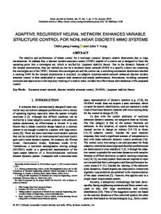
There are essentially three elements in the WSAN architecture: sensors, actuators and base station (sometimes refereed as controller). The role of each element has been discussed previously. There are two schemes to build the network, automated and semi automated [3]. Figure.1 shows the architecture of semi automated which will be used to implement the approach of the MRANNC. In this scheme, there is no explicit controller in the WSANs. The controller and the actuator A are connected directly. The controller receives the measured data of the output from the sensor S. After doing some processing, the signal is sent to the actuator to drive the system according to some specified algorithm. The error signal is given as e(k) = r(k) – y(k)
(1)
Where r(k) is the reference signal and y(k) is the plant output. The measure of performance of the control system is done by using the performance index (PI). The integral time squared error (ITSE) which can be given by ITSE= ∫ t e2(t) dt
(2)
Wireless Communication Network
A
Plant
Fig 1: Schematic Diagram of WSAN
u(k)=yn(k)+am1yp(k)+am2yp(k)+bm1r(k)+bm2r(k)
(3)
The plant output can be calculated as
3. SYSTEM ARCHITECTURE 3.1 WSAN Model
Base Station
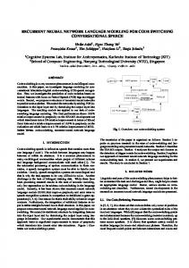
The Adaptive Linear (ADALINE) neural network [14] is used to update the controller parameters and calculate the control signal for our proposed WSAN system in Fig. 1. The training of the NN will store the plant dynamics. The output of the system can be estimated by reference model and the NN. The schematic diagram of the MRANNC is depicted in Fig. 2. The control signal is calculated by the controller C and it depends on the NN output and the output of the model, it can be given as
S
(4)
where u : Control signal. ym : Model output. yp : Plant output. yn : Neural Network output. r : Reference input. am,,bm : Model parameters In WSAN system, the use of this scheme for compensation of the packet loss thanks to the learning applied by neural network and reference model. Three issues should be noted to investigate the link quality of wireless networked control systems, they are [15] Packet loss There is a high probability to loss some information in wireless network. It can be caused by disturbing effects of environment or long distance between nodes. When the packet is dropped out, retransmission of data is possible when the sampling interval is relatively large. The received sample is used again for computation and processing. Sampling interval Sensors usually sample process output values in either periodic or aperiodic (event based) times in networked control systems. For most of the dynamical systems, more samples leads to better control of systems. The higher sampling rates can cause overload for the network. This leads the network to induce time delays and hence the implementation of real time control system is more difficult. Number of nodes One of the aims of using wireless communication network technology is to control many systems over the same
11
International Journal of Computer Applications (0975 – 8887) Volume 62– No.11, January 2013 network. Multiple systems can cause network overload because there is higher expectancy that there is more than one node wants to transmit data through the same channel at the same instant.
r Reference Model
e ynn NN
u Controller
y
Plant
Fig 2: MRANNC Scheme Thereby, in this paper the use of proposed MRANNC for compensation of packet loss in WSANs can be implemented on the following discrete system by y (k+1) = -0.0007y(k) +0.093y(k-1) + 0.853u(k-1) +0.0406u(k-2)-0.0011u(k-3)+0.0046u(k-4)
(5)
The reference model is given by ym (k+1) = 0.6622ym (k) +0.1689r(k) +0.1689r(k-1)
(6)
y (k+1) and ym (k+1) defined Equations (5) and (6) are used to determine the output of the controlled plant and the output of the reference model respectively. Their values are founded by using Tustin method with a sampling time of 0.05 second.
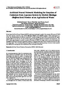
3.3 Wireless MRNNC The wireless medium that is used for data exchange between the sensor and the controller (base station) is simulated by using Truetime 1.5 simulator [16]-[18]. The wireless network type that has been used is wireless local area network (WLAN) with the IEEE 802.11b standard. The parameters of the network settings are created in Fig. 3. The block diagram of the wireless control system is illustrated in Fig. 4. There are two nodes communicate wirelessly, through a wireless network, node 1 and node 2. The output of the plant y is sensed by node1 via the A/D pin. The second output of node1 to the plant u is used to actuate the plant. The wireless network receives two signals wirelessly from controller and sensor and it also sends two signals to both nodes.
4. SIMULATION RESULTS 4.1 Performance Evaluation The use of MRANNC scheme for compensation of packet loss in WSANs is implemented using equations (1)-(5) of Subsection 3.2. The parameters of the wireless sensor and actuator network are illustrated in Fig. 3 while the parameters of the ADALINE neural network are defined as follows L=0.9455 which stands for design error gain. LE=0.000036 which stands for learning rate. tm =0.05 second which is being a sampling time.
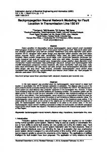
Fig 3: The dialogue Box of Wireless Network Parameters Used in Truetime 1.5 It is clearly found that the initial weights can be chosen randomly [-1, 1]. The system is tested with various step inputs to check the response. It is obvious from Fig. 5 that the output response of the system is without packet loss. The output of the plant tracks well the required reference input. Figure 6 and 7 represents the response of the system with a packet drop out at samples 5000 and 9000, respectively. The output of the plant is decayed; due to packet loss; at those instants and after a transient time the control efforts of adaptive controller, the plant output and reference input are identical. Figure 8 shows the response of the system without a time delay; while Fig. 9 depicts the same response when a time delay is added by 0.06s. The simulations are implemented by using Truetime1.5 simulator under Matlab/Simulink (R2010b) environment. It is clear that performance and stability is good when the MRANNC is used for link quality enhancement.
4.2 Results Comparison The results of our new scheme are generally compared to other works of such issues of link quality in wireless sensor and actuator networks. In [3][5][19] and [20], there exist a lot of work that have been done to discuss the aspects of link quality. For instance, in [3], the algorithm that they have been used to compensate for packet loss made the system response seems to be with very high overshoot (approximately 57% of the reference value) and also the steady state error is very high.
12
International Journal of Computer Applications (0975 – 8887) Volume 62– No.11, January 2013
Fig 4: Schematic Diagram of Wireless MRNNC Using Truetime 1.5 Simulator
10 model output (ym) plant output (y)
ym / y
8 6 4 2 0 0
1000
2000
3000
4000 5000 6000 no. of samples
7000
8000
9000 10000
Fig 5: System Step Response without Packet Loss
13
International Journal of Computer Applications (0975 – 8887) Volume 62– No.11, January 2013
10 model output (ym) plant output (y)
ym / y
8 Packet Loss
6 4 2 0 0
1000
2000
3000
4000 5000 6000 no. of samples
7000
8000
9000
10000
Fig 6: System Step Response with Packet Loss at the Sample 5000
10 model output (ym) plant output (y) 8
ym / y
Packet Loss 6 4 2 0 0
1000
2000
3000
4000 5000 6000 no. of samples
7000
8000
9000
10000
Fig 7: System Step Response with Packet Loss at the Sample 9000
10
model output (ym) plant output (y)
ym / y
8 6 Packet Loss 4 2 0 0
1000
2000
3000
4000 5000 6000 no. of samples
7000
8000
9000
10000
Fig 8: System Step Response with Packet Loss at the Sample 3000 without Time Delay
14
International Journal of Computer Applications (0975 – 8887) Volume 62– No.11, January 2013
10 model output (ym) plant output (y)
ym / y
8 6 Time Delay
Packet Loss
1000
3000
4
No Packet Loss No Time Delay
2 0 0
2000
4000 5000 6000 no. of samples
7000
8000
9000
10000
Fig 9: System Step Response with Packet Loss at the Sample 3000 with Time Delay of 0.06
1.5 plant output (y) reference input (r) 1
r/y
0.5 0 -0.5 -1 0
Packet Loss 1
2
3 no. of samples
4
5
6 4
x 10
Fig 10: System Variable Step Response with Packet Loss [5]
Specifically, the results of our proposed scheme are compared with that of [5] by Xia et. al. They estimated the control signal by a PID algorithm for previous control signals when the packet loss has occurred as shown in Fig. 10. The response of their system contains a high overshoot, long settling time and residual steady state error. The wireless control system that uses the MRAC scheme is proved as a suitable control scheme to compensate for packet loss and time delay in wireless sensor and actuator networks.
5. CONCLUSIONS In this paper, the link quality of the WSANs has been improved using proposed adaptive controller which basically employs off-line trained artificial neural networks to compensate the packet loss and delay in wireless control system. The results show that the response of the control
system introduces good performance. The use of the MRANNC for wireless networked control system is investigated by building a Matlab program code to compensate for packet loss and to enhance the performance of the networked control system. Simulation results show that a good stability of the system can be achieved when there is a packet loss and the system tracks well its input reference. A comparison also has been made with some papers addressing the same field.
6. ACKNOWLEDGMENTS We would like to express our gratitude to Professor Raad S. Fyath from Al-Nahrain University, College of Engineering for his valuable comments and directions to complete this work.
15
International Journal of Computer Applications (0975 – 8887) Volume 62– No.11, January 2013
7. REFERENCES [1] Verdone., R., Dardari, D., Mazzini, G., and Conti, A. 2008. Wireless sensor and actuator networks. University of Bologna. [2] Akyildiz, I. F. and Vuran, M. 2010. Wireless sensor networks. John-Whily & sons. [3] Mazumder, S. 2011.Wireless networking based control . Springer. Chapter 7, pp.85-102. [4] Nayak, A. and Stojmenovic, I. 2010 .Wireless sensor and actuator networks . John-Whiley & sons. [5] Xia, F., Tian, Y. and Sun, Y. 2007 Wireless sensor/actuator networks for mobile control. Sensors 7(10), pp. 2157-2173. [6] Melodia, T. Pompili, M. and Akyilidiz, I. F. 2010. Handling mobility in wireless sensor and actuator networks. IEEE Transaction on mobile computing, 9(2), pp. 160-173. [7] Li, S. 2006 .Wireless sensor actuator networks for light monitoring and control applications. proc. 3rd IEEE consumer communication and networking conf., pp. 974978.
[11] Ngai, E., Liu, J. and Lyu, M. 2007.Delay – minimized route design for wireless sensor-actuator networks. IEEE WCNC. [12] Haspanha, J., Naghshtabriz, P., and. Xu, Y. 2007.Survey of recent results in networked control systems. in Proc. of IEEE pp.132-162. [13] Morles, C., and Neil, C. 1993.Neural networks based adaptive control design. Journal of system Engineering, Springer-Verlag. [14] Omatu, S., Khalid, M., and Yousif, R.1996. Neuro control and its applications. Springer-Verlag. [15] Kawka, P. and Alleyne, A.2005. Stability and feedback control of wireless networked systems. in American Control conference, Portland, OR, USA, pp.2953-2959. [16] Henriksson, D., Ohlin, M., and Cervin, A. 2006. Truetime simulations of networked computer control systems. 2nd IEAC conference on analysis and design of hybrid systems. [17] Martin, A., Henriksson, D., Cervin, A., and Arzen, K. 2005. Simulation of wireless networked control systems. In proc. 44th IEEE Conf. on Decision and Control, pp.476-481.
[8] Mostofi, Y. and Murray, R. 2004. Effect of time varying fading channels on the control performance of mobile sensor node . in Proc. of IEEE 1st Inter. Conf on sensor and Ad hoc Communications and Networks (Secon) .
[18] Vardhan, S., and Kumar, R. 2011. Simulation of time delay compensation in networked control systems. Cyber Journals; Multidisciplinary Journals in Science and Technology, pp.38-43.
[9] Liu, X., and Goldsmith, A. 2004 .Wireless network design for distributed control. in Proc. IEEE Conf. on Decision and Control, pp. 2823-2829.
[19] Yang, Y., Viktor K., and Chari, K. 2006. Information processing and routing in wireless sensor network. World Scientific publishing Co. Chapter1, pp.1-21.
[10] Colandiraj, J. , Irwin, G. and Scanlon, W 2007.Wireless networked control system with QoS-based Sampling IET Control Theory & Applications.
[20] Carlos, M., and Dharma, P. 2011. Ad-hoc and sensor network: Theory and applications. World Scientific publishing Co. Chapters 1, 3, 5, 7, pp.1-317.
16