Adaptive Path Planning for Tracking Ocean Fronts with an Autonomous Underwater Vehicle Ryan N. Smith, Frederic Py, Kanna Rajan, and Gaurav S. Sukhatme
1
Motivation, Problem Statement, Related Work
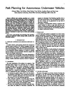
An oceanic front is a narrow band of enhanced horizontal gradients of water properties (temperature, salinity, nutrients, etc.) dividing broader areas with different water masses or vertical structure. Fronts occur across a variety of spatial scales; along-frontal scales of 1 km to 10,000 km, cross-frontal scales of 10 m to 100 km, and vertical scales of 10 m to 1000 m. Temporal scales vary from days for transient fronts to millions of years for quasi-stationary, largescale transoceanic fronts. Ocean fronts have been linked to elevated primary production and enhanced diversity of species; hot spots for marine life, across an astonishing spectrum of scales from plankton to whales. These frontal hot spots hold a wealth of information to improve our understanding of aquatic ecosystems in relation to climate change, however ocean fronts cannot be studied through conventional oceanographic techniques [1]. It is of interest to determine whether or not it is possible to develop a biological model for activity at or within an ocean front for ecological purposes. At the high level, we envision the scenario shown in Fig. 1, with the objective that coordinated observation between aerial, surface and underwater platforms are critical in observing dynamic biological phenomenon with varying spatial and temporal scales (from minutes to weeks and few sq. km to tens of sq. km). In this paper, we address the problem of sampling and tracking Fig. 1. An envisioned scenario an ocean front with an Autonomous Underwater in the near future, with the use Vehicle (AUV) based on predictions and/or pri- of AUVs, autonomous surface ors provided by the heterogeneous team of assets and aerial platforms finding, and ocean models. Specifically, given a prior (that tracking and sampling frontal is probably not accurate) can the AUV adapt its zones. mission to find and track a dynamic feature? Robotic platforms hold the promise of a revolution in ocean sampling. Considerable study has been reported on control design for AUVs for adaptive ocean Shore
UAV
AUV
ASV
Fronta
l Zone
Mooring with Comm gateway
AUV
R.N. Smith is with the Physics and Engineering Department, Fort Lewis College, Durnago, CO, USA, email:
[email protected] F. Py and K. Rajan are with the Monterey Bay Aquarium Research Institute, Moss Landing, CA USA, email: kanna.rajan,
[email protected] G.S. Sukhatme is with the Robotic Embedded Systems Laboratory and the Dept. of Computer Science, University of Southern California, Los Angeles, CA 90089 USA e-mail:
[email protected]
2
R.N. Smith, F. Py, K. Rajan and G.S. Sukhatme
sampling and coordinated control of multi-vehicle systems, [2–8]. Applications of ocean sampling techniques for AUVs are discussed in [5, 6, 9], with ocean front perception detection addressed in [10]. Along with steering an AUV to the right locations, research exists in the area of static sensor placement to maximize knowledge return, [11]. Existing methods are currently all based on a geographical coordinate system, i.e., latitude and longitude. However, the definition of geographical space is ill-defined in the ocean and complex ocean dynamics make geographic-relative navigation difficult, specifically when tracking dynamic and episodic events. Sampling at uniformly distributed geographic coordinates can generate a suboptimal distribution of samples given the dynamic nature of the oceans’ water masses. Some results have used information-based metrics and machine learning to optimally determine a path or sensor placement based on reduction of overall covariance of the scalar field in question. Recent work in [2] begins to address this issue, but approaches the problem from a multiple underwater vehicle point-of-view with constrains on communication among the fleet. Here, we enable in situ robotic adaptation for a single vehicle to environmental conditions based on real-time measurements for targeted sampling.
2
Technical Approach
For this research, field experiments were carried out in Monterey Bay, California with a YSI EcoMapper AUV [12], as shown in Fig. 2. As our focus is on the
Fig. 2. The YSI Ecomapper Vehicle (top) and the beach deployment of the vehicle (bottom).
Fig. 3. A schematic of the survey problem.
Fig. 4. Representation of the initially computed survey path.
mission adaptation of the AUV, we provide the vehicle with a prior estimation characterizing the location of an ocean front from an Unmanned Aerial Vehicle (UAV), Fig 3. This prior is provided as a KML file as is assumed to be temporally latent and inaccurate. The KML file is the input to our algorithm to plan an initial path to survey the observed ocean front. As it is assumed that the front has moved since the observation, the initial path plan is very conservative with
Adaptive Path Planning for Tracking Ocean Fronts
3
regard to the spatial footprint of the front. From the provided observation, we parameterize the boundary of the front to a curvilinear line in 2D. We assume that a front can be represented as a single1 , continuously-differentiable function, i.e., C 1 . The initial path plan is computed on-board the AUV be a regular, zig-zag pattern, crossing the frontal boundary with a predefined swath width, Fig. 4. For our initial experiments this swath width was 200 m. Assuming the speed over ground of the vehicle is constant, we vary the speed along the parameterized frontal boundary by expanding or contracting the size of the zig-zags, similar to what was done in [5]. Here we rotate the planning method 90◦ to generate zig-zag paths in the horizontal plane, where the degree of compression of each zig-zag is proportional to the inverse of the derivative (curvature) of the parameterized boundary at each location. Specifically, in areas of low curvature we achieve regular sampling, and in areas of high curvature, we perform higher density sampling to accurately resolve the changes. The adaptation of the sampling path occurs incrementally as the vehicle follows and samples within the front. The low-level functionality of navigation to a specified location is handled through a ROS interface on-board the vehicle. The high-level decision of plan synthesis is executed on-board by the Teleo-Reactive EXecutive (T-REX) [13, 14]. For each transect (Ti ) that crosses through the front, T-REX perceives and records the location (li ) of the frontal boundary based on a technique similar to that presented in [10]. To begin, the vehicle executes the first three transects of the initially computed path. During this phase, T-REX allows the vehicle to continue past a prescribed waypoint if it perceives that the vehicle is still within the front, and allows the vehicle to stop early if it perceives that the vehicle has already exited the front. These initial frontal boundary locations, li for i = 1, 2, 3 are input into a cubic spline algorithm that estimates the most likely location of the frontal boundary. T-REX then generates the next waypoint based on this estimated location. This process is iterated until the front is no longer detected. After the execution of the initial three waypoints, the path planning is simply determining a vehicle heading based on predicted curvature of the frontal boundary, while the length of the trajectory is determined by in situ sampling. We also implement a forgetting factor in our estimations by only considering, at most, the previous 4 waypoints for input to the cubic spline to estimate the location of the front.
3
Experiments
Experiments were carried out near the harbor channel mouth in Moss Landing, CA, directly in front of the Monterey Bay Aquarium Research Institute (MBARI). The EcoMapper AUV was deployed and recovered from the beach, enabling ease of multiple tests without the need for significant support infrastructure. To validate the utility of the algorithm based on an ability to ground truth results, we chose a fixed depth as a non-dynamic pseudo-front to examine and track. Monterey Canyon, located at the center of Monterey Bay, is the largest 1
A discontinuity is assumed to represent two different fronts, and ocean physics negate the possibility of non-differentiable locations along a front.
4
R.N. Smith, F. Py, K. Rajan and G.S. Sukhatme
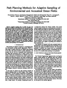
submarine canyon along the coast of North America, and begins at the mouth of the harbor channel, see Fig. 5. By choosing a fixed depth, and zig-zagging across the canyon edge, we emulated a reliable feature for testing our tracking methodology. The initial prior for the canyon edge is shown by the curved, white line in
Fig. 5. Relief of the Monterey Canyon.
Fig. 6. A delineation of the chosen Monterey Canyon depth contour as the initial prior for the pseudofront (white). The initially computed path for the AUV is shown in red.
Fig. 6. This was delineated by hand from existing bathymetry maps and from analyzing data collected from previous vehicle deployments within the region. The initially computed path based on this prior is given by the zig-zag, red line in Fig. 6. The AUV started its mission at a set deployment location, then navigated on the surface of the water to the first waypoint of the path (furthest East), then executed the prescribed path, heading westerly. The AUV operated at a constant depth of 2 m from the surface for the entire mission. During the experiments, the T-REX was operating and making decisions, but was not pushing these decisions down to ROS for execution during the mission. Thus, we have the revised path as computed by T-REX for the mission to compare with ground truth data, however that path was not executed by the vehicle in an in situ adaptive fashion.
4
Results
The experiment was executed multiple times with different delineations for the initial prior of the front, as well as different initial swath widths for the zig-zag path. The frontal boundary was set to coincide with a depth of 6 m. An example execution of the initial path is shown in Fig. 7. The adaptively-computed path is shown by the white dotted line connecting the iteratively computed white waypoints in Fig. 8. Although we did not executing the adaptively computed path, we demonstrated that we are able to compute adaptations to the path, enabling the vehicle to follow a prescribed contour using on-board computation.
Adaptive Path Planning for Tracking Ocean Fronts
5
Fig. 7. Depth recorded during the execution of the mission in Monterey Bay.
Fig. 8. Placeholder for the figure with recomputed waypoints.
5
Main Experimental Insights
Thus far, we have carried out field trials to execute a prescribed path based on a prior delineation of a frontal boundary. We have demonstrated that we can compute new commands to follow a desired contour on-the-fly through and integration of ROS and T-REX. Some preliminary results are summarized as follows. 1. We have demonstrated a successful integration of ROS and T-REX on-board an AUV for adaptive, goal-oriented mission execution. 2. We have presented an algorithm for tracking a frontal boundary with adaptive path planning based only on a prior delineation from remotely sensed data. 3. It was initially thought that a plume or front could be detected emerging from the harbor on a regular interval associated with the tidal cycle. This was the case, but without an aerial vehicle, or other method, to provide the initial (georeferenced) prior, computing an appropriate initial path proved very difficult. Currently, we are investigating the integration of ocean model predictions to inform the vehicle of how the frontal system has moved prior to the start of the survey, or how it is moving during the execution of the mission. Combining the ocean model predictions with the cubic spline estimations will provide a longer
6
R.N. Smith, F. Py, K. Rajan and G.S. Sukhatme
horizon for path planning and hopefully place the AUV in the right place at the right time to sample the frontal boundary. In future work, we aim to evaluate the utility of this method for sampling an actual ocean front. The difficulty here lies in the location and initial delineation of such a feature. As presented in [2] the use of ocean model data for validation through simulations will be an initial step prior to field deployment.
References 1. Olson, D., Hitchcock, G., Mariano, A., Ashjan, C., Peng, G., Nero, R., Podesta, G.: Life on the edge: marine life and fronts. Oceanography 7 (1994) 52 – 60 2. Reed, B., Hover, F.: Tracking ocean fronts with multiple vehicles and mixed communication losses. In: Intelligent Robots and Systems (IROS), 2013 IEEE/RSJ International Conference on. (Nov 2013) 3374–3381 3. Yuh, J.: Design and Control of Autonomous Underwater Robots: A Survey. Autonomous Robots 8 (2000) 7–24 4. Paley, D., Zhang, F., Leonard, N.: Cooperative control for ocean sampling: The glider coordinated control system. IEEE Transactions on Control Systems Technology 16(4) (July 2008) 735–744 5. Smith, R.N., Schwager, M., Smith, S.L., Jones, B.H., Rus, D., Sukhatme, G.S.: Persistent ocean monitoring with underwater gliders: Adapting sampling resolution. Journal of Field Robotics 28(5) (September/October 2011) 714 – 741 ` Gar6. Smith, R.N., Das, J., Heidarsson, H., Pereira, A., Cetini´c, I., Darjany, L., Eve neau, M., Howard, M.D., Oberg, C., Ragan, M., Schnetzer, A., Seubert, E., Smith, E.C., Stauffer, B.A., Toro-Farmer, G., Caron, D.A., Jones, B.H., Sukhatme, G.S.: USC CINAPS builds bridges: Observing and monitoring the Southern California Bight. IEEE Robotics and Automation Magazine, Special Issue on Marine Robotics Systems 17(1) (March 2010) 20–30 7. Smith, R.N., Chao, Y., Li, P.P., Caron, D.A., Jones, B.H., Sukhatme, G.S.: Planning and implementing trajectories for autonomous underwater vehicles to track evolving ocean processes based on predictions from a regional ocean model. International Journal of Robotics Research 29(12) (October 2010) 1475–1497 8. Smith, R.N., Das, J., Chao, Y., Caron, D.A., Jones, B.H., Sukhatme, G.S.: Cooperative multi-auv tracking of phytoplankton blooms based on ocean model predictions. In: Proceedings of Oceans ’10 - IEEE Sydney, Sydney, Australia (May 2010) 1 – 10 9. Singh, H., Yoerger, D., Bradley, A.: Issues in auv design and deployment for oceanographic research. In: Proceedings of the 1997 IEEE International Conference on Robotics and Automation. Volume 3. (1997) 1857–1862 Invited paper. 10. Zhang, Y., Bellingham, J.G., Godin, M.A., Ryan, J.P.: Using an autonomous underwater vehicle to track the thermocline based on peak-gradient detection. IEEE Journal of Oceanic Engineering 37(3) (July 2012) 544 – 553 11. Zhang, B., Sukhatme, G.S.: Adaptive sampling with multiple mobile robots. In: IEEE International Conference on Robotics and Automation (submitted). (2008) 12. YSI Incorporated: Ysi ecomapper. http://www.ysi.com/productsdetail.php? EcoMapper-41 (2010) Viewed August 2010. 13. Rajan, K., Py, F.: T-REX: Partitioned Inference for AUV Mission Control. In Roberts, G.N., Sutton, R., eds.: Further Advances in Unmanned Marine Vehicles. The Institution of Engineering and Technology (IET) (August 2012) 14. Rajan, K., Py, F., Berreiro, J.: Towards Deliberative Control in Marine Robotics. In Seto, M., ed.: Autonomy in Marine Robots. Springer Verlag (2012)