www.ccsenet.org/cis
Computer and Information Science
Vol. 3, No. 4; November 2010
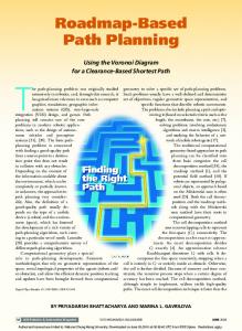
A Path Planning Method Based on Adaptive Genetic Algorithm for a Shape-shifting Robot Mengxin Li, Xinghua Xia & Ying Zhang School of Information and Control Engineering, Shenyang Jianzhu University Shenyang 110168, China Tel: 86-24-2469-2899
E-mail:
[email protected] Tonglin Liu
State Key Laboratory of Robotics, Shenyang Institute of Automation, Chinese Academy of Sciences Shenyang 110016, China Abstract A shape-shifting robot with changeable configurations can accomplish search and rescue tasks which could not be achieved by manpower sometimes. The accessibility of this robot to uneven environment was efficiently enlarged by changing its configuration. In this paper, a path planning method is presented that integrates the reconfigurable ability of the robot with the potential field law. An adaptive genetic algorithm is applied to solve effectively the local minimum problem. The experiments show that the robot’s configurations can be changed to perform the path planning with the environmental variation. Moreover, the path has been shortened effectively. Keywords: Reconfiguration, Shape-shifting, Path planning, Robot To achieve different tasks and adapt various environments such as search and rescue, military reconnaissance, and mine exploration, the flexibility of the traditional robots is too worse to meet the needs. A reconfigurable mobile robot has attracted a lot of attention and interest for wide applications. Because of automatic reconfigurable ability, it can complete the search and rescue task by changing the configurations to adapt with the dangerous, unknown environment. Up to now, there have been a lot of research groups outside China which study reconfigurable mobile robot: USC-ISI, CMU, AIST , Fukuda Laboratory and et al. In China, scientists in Shanghai Jiao Tong University Shenyang Institute of Automation, Chinese Academy of Sciences, Beijing university of aeronautics and astronautics, Harbin Institute of Technology, and et al. The path planning of robot is key research topics, which determines a robot whether can perform completing tasks on time in complex environment. At present, many path planning algorithms have been researched, such as Rolling Path Planning Method, Genetic Algorithm, Ant Colony Algorithm[and Visibility Graph. One of the well known methods is the potential field method with rapid description of the environment, which is widely used for real-time obstacle avoidance and motion planning. It minimizes a penalty function that consists of two components describing influence of the obstacles in the workspace and the intention to go to the desired point. 1. System of the shape-shifting robot The shape-shifting robot with the automatic reconfigurable ability adopts modular structure. The adaptability of the robot is reinforced in the different space by changing the configurations. The six ultrasonic sensors are emplaced in three regions of the platform, 2 sensors are fixed on the left and right of frontage respectively, 2 sensors are fixed on the front and rear of right side respectively, and 2 sensors are fixed on the front and rear of left side respectively. The detecting-distance of the every ultrasonic sensor is 4cm-5m, and they are asynchronously transmitted. An electron compass, a GPS and an inclinometer are emplaced in the platform respectively. The shape-shifting robot has diverse configurations. The reconfigurable capacity of the robot will be reinforced by using every motion joint. Four kinds of commonly used configuration of the shape-shifting robot, i.e. configuration R, T, d, L. The control system is composed of a wireless module, a main control module, motor control modules and sensor-based feedback control modules. Main control module is the robot’s decision-making unit, which estimates its own position, and plans path and changes its own configuration according to information of environment provided by the feedback control module. The sensor-based feedback system contains controllers 8 to 11 as well as electron compass, GPS, inclinometer 208
ISSN 1913-8989
E-ISSN 1913-8997
www.ccsenet.org/cis
Computer and Information Science
Vol. 3, No. 4; November 2010
and ultrasonic sensors. The controller 11 receives the data of every controllers of ultrasonic sensors by CAN bus and processes them. All sensors receive information from the environment and transmit the data to respective controllers in which pre-settled algorithms are used to deal with them, and then results are sent to the PC. 2. Modified potential field method 2.1 Calculation of Attractive and Repulsive Forces In the motion space, the robot is considered as one particle, and the particle receives effect of potential field force, according to the basic idea of potential field method. In the potential field approach every obstacle exerts a repulsive force on the robot and target position exerts an attractive force. According to characteristic which the shape-shifting robot has reconfigurable capacity, the shape-shifting robot is considered as a robot which will be reduced proportionally, and keep the reconfigurable ability which change the configurations to strengthen the accessibility. The amplitude of the repulsive force is defined as: 2
Fr w1e c1 ( dr a )
(1)
Where w1, c1 and a are constant coefficients respectively. dr is distance between the current robot location and the obstacle location. Its value is calculated as follows:
d r xo2 yo2 ( x xo ) 2 ( y yo ) 2
(2)
where △xo and △yo are coordinate distances between the robot position and the obstacle position. We proposed the following law for attractive force:
w2 d a 6 | X X t | Fa k1w2 d a 3 | X X t | 6 k w d | X X t | 3 2 2 a
(3)
where X is current position coordinate of the robot. Xt is position coordinate of target. w2, k1 and k2 are constant coefficients respectively. The k1 and k2 are involved to reach the target when the distance da between the current robot location and the target location are located into the circle with radius (3, 6] m or 3m. The value da is calculated as follows:
d a xt2 yt2 ( x xt ) 2 ( y yt ) 2
(4)
The force controlled on the robot:
Fs min( Fr Fa )
(5)
where the resulting vector Fs is obtained as a minimum of the vector sum of repulsive force Fr and attractive force Fa. 2.2 Method of accessibility In terms of complicated environments and irregular polygonal obstacles, if stacking potential fields of all obstacles, the time consumption for computation would be too large to perform the task in real-time application. The concept of the visibility field is introduced according to location of sensors. The shape-shifting robot only needs to avoid obstacles detected. The robot’s scope of the visibility field here is a rectangle with the length a=8m and width b=4m according to measuring range of ultrasonic sensor, as shown in Figure 1, where obstacles 2, 3 and 4 are visible, obstacles 1 and 5 is not visible. In order to further reduce the computation load, Firstly, nearest obstacle from the robot, the distance of the obstacles and obstacles which locate along both sides of robot’s path are all considered to satisfy the width of a certain configuration of the robot. If there is only one obstacle in the scope of the visibility field, it is very easy for avoidance. If there are many obstacles in the scope of the visibility filed, the robot needs to calculate the maximum resultant forces Frmax of two nearest repulsive forces before going through the two obstacles.
Fr max Fr1 Fr 2
(6)
where Fr1 and Fr2 are repulsive forces of two nearest obstacles which the robot intends to pass through.
Published by Canadian Center of Science and Education
209
www.ccsenet.org/cis
Computer and Information Science
Vol. 3, No. 4; November 2010
The current control force on the robot: Fs min( Fr max Fa )
(7)
Corollary1. Due to the effect of resultant repulsive force Frmax when control force of (7) is implemented, we can derive the rule that the robot movements towards the centric position of two obstacles and goes through along the path near the centric position. According to (1), (6) and corollary 1, we can get the relationship between configuration of the robot and maximum repulsive force Frmax, as represented in Table 1. sT, sd and sL are halves of width of configuration T, d and L respectively. Δd1 and Δd2 are smaller adjustment quantity. Thus the robot can automatically select a proper configuration that satisfies the distance between two obstacles. In Figure 2(a), the shape-shifting robot doesn’t adopt reconfigurable method. The robot discovers that obstacle 2 is the nearest from robot, when it moves to the target. The robot hopes that obstacle 2 is bypassed. The path of first choice is l1, but the robot discovers that the distance between obstacle 2 and obstacle 5 is less than the width of robot with the configuration T. The path l2 of secondary choice is in the same way. So the robot had chosen the farther path l3. In Figure 2(b), the shape-shifting robot with two kinds of reconfigurations can change its own configuration to choose the nearer path l2 and can pass through obstacles successfully according to the environmental variation. In Figure 2(c), the shape-shifting robot with three kinds of reconfigurations can change its own configuration to choose the nearest path l1. Therefore, the better the reconfigurable ability of the robot is, the better the adaptive ability of environment is. 2.3 Solving the local minimum problem In some case, the robot only knows the surrounding environment of current location in complex environment, so it falls into the local minimum easily. Therefore this paper adopts an adaptive genetic algorithm (AGA) as following to estimate and escape from the local minimum: AGA can choose crossover operator and mutation operator adaptively according to fitness, which result in morerapidly convergence speed comparing with traditional GA. It is more important AGA is used to avoid local minimum. Crossover operator, Pc, and mutation operator, Pm have influence on behavior of GA, which are changed with fitness. When all the fitnesses of population are tended to be consistent. Pc and Pm are added. When all the fitnesses are dispersed, Pc and Pm are reduced.. The individuals which have lower Pc and Pm corresponding to higher fitness than average fitness are protected to go to next generation. While the individuals which have relatively highly Pc and Pm corresponding to lower fitness than average fitness are removed. Pc and Pm are given by:
( Pc1 Pc 2 )( f ' f av ) Pc1 f max f av Pc P c1 ( Pm1 Pm 2 )( f max f ) Pm1 f max f av Pm P m1
f ' f av
(8)
f ' f av f ' f av
(9)
f ' f av
where f is fitness, f′is derivative of f,; fav is average of f, fmax is max of f, and Pc1 , Pc 2 Pm1 Pm 2 are fitted to 0.9,0.6,0.1,0.001 respectively. 3. Experiment of accessibility and simulation of path planning 3.1 Experiment of accessibility In order to validate effectiveness of the method, we do the experimental research on the autonomic accessibility of the shape-shifting robot. In an unknown condition of obstacles, the robot can change its movement route for obstacles avoidance according to the information of sensors. Also, the robot can estimate the distance between the neighboring obstacles. Then, it automatically adjusts its own configuration to reinforce the adaptability of environment. 3.2 Simulation of path planning The simulation experiments have been done in the same complex environment with polygonal obstacles using
210
ISSN 1913-8989
E-ISSN 1913-8997
www.ccsenet.org/cis
Computer and Information Science
Vol. 3, No. 4; November 2010
the method proposed, as represented in Figure 3, Figure 4 and Figure 5. In these figures, the red rectangle is start position, the red circle is target position. In Figure 3, with the modified potential field method, the robot with the fixed configuration T completed path planning efficiently in the environment with polygonal obstacles. In Figure 4, the robot with two kinds of reconfigurations can change its own configuration to complete path planning according to the environmental variation, after integrating the reconfigurable ability of the robot into the modified algorithm. We can find out: the method well solved the local minimum problem in situation of irregular obstacles. In Figure 5, the robot with three kinds of configurations can change its own configuration to perform path planning more effectively according to the environmental variation than before. When the robot passed through first narrow space, it transformed its own configuration from T to d. While the robot passed through secondary narrower space, it changed its own configuration from T to d to L. 4. Discussion and Conclusions In this paper, a modified potential field method is presented to describe environment rapidly. Moreover, with AGA, the local minimum problem is solved to make sure real-time application effectively. In addition, the proposed method has a very strong capability of acclimatization. It has been validated through experiment results that the robot can change its own configuration to perform the path planning with the environmental variation. Furthermore the method proposed can shorten the path effectively. References Bhat P S, Kuffner J, Goldstein S, et al. (2006). Hierarchical motion planning for self-reconfigurable modular robots. In: Proceedings of IEEE International Conference on Intelligent Robots and Systems.pp.886 - 891 Fei Y Q, Zhao X F. (2005). Modules classification and automatic generation of kinematics on self-reconfigurable modular machines. J Intell Robot Syst. pp. 147-159 Kamimura A, Kurokawa H, Yoshida E, et al. (2005). Automatic locomotion design and experiments for a modular robotic system. IEEE-ASME Trans Mechatron. pp. 314-325 Liu J G, Ma S G, Wang Y C, et al. (2008). Reconfiguration routes research for a self-reconfigurable robot based on network. Science in China Series F-Information Sciences. pp.1532-1546 Takagawa I, Sekiyama K, Fukuda T. (2003). Coevolution of physical configuration and control strategy on self-reconfigurable flexible transfer system. In: Proceedings of IEEE International Conference on Intelligent Robot and Systems.pp. 2474-2479 Wang T M, Zou D, Chen D S. (2005). Mechanism design and control method of reconfigurable tracked robot. J Beijing Univ aeronaut (in Chinese), pp.705-708 Wei Y H, Zhao J, Cai H G. (2006). Task-based method for determining topology of reconfigurable modular robot. Chinese J Mech Engin (in Chinese).pp. 93-97 Wu Q X, Cao G Y, Fei Y Q. (2006). Motion simulation and experiment of a novel modular self-reconfigurable robot. J Southeast Univ. pp.185-190 Yim M, Shen W Malemi B, et al. (2007). Modular self-reconfigurable robot systems. IEEE Robotics & Automation Magazine.pp.43-52 Yu H B, Yu J J, Bi S S, et al. (2005). Configuration synthesis of reconfigurable robot based on graph theory. Chinese J Mech Engin (in Chinese).pp. 79-83
Published by Canadian Center of Science and Education
211
www.ccsenet.org/cis
Computer and Information Science
Vol. 3, No. 4; November 2010
Table 1. Condition of the robot changing the configuration configuration
condition c1 (( sT d1 ) 2 a )
T
Fr max w1e
d
Fr max w1e c1 (( sT d1 )
2
2
a)
w1e c1 (( sT d2 )
2
a)
2
a)
2
a)
w1e c1 (( sd d2 )
Fr max w1e c1 (( sd d1 )
2
a)
w1e c1 (( sd d2 )
2
a)
Fr max w1e c1 (( sL d1 )
2
w1e c1 (( sL d2 )
2
a)
Fr max w1e c1 (( sd d1 )
L
a)
w1e c1 (( sT d2 )
r3
a)
r2 r4
Figure 1. The visibility field of the robot. s is the scope of the visibility field, 1, 2, 3, 4 and 5 is obstacles
d2
l2 l1 d1 d3
l3
(a)
212
ISSN 1913-8989
E-ISSN 1913-8997
www.ccsenet.org/cis
Computer and Information Science
d2
Vol. 3, No. 4; November 2010
l2 l1 d1
d3
l3
(b)
d2
l2 l1 d1
d3
l3
(c) Figure 2. Robot’s passing through the narrow space 30
25
20
15
10
5
0
0
5
10
15
20
25
30
Figure 3. Robot path planning with the configuration T
Published by Canadian Center of Science and Education
213
www.ccsenet.org/cis
Computer and Information Science
Vol. 3, No. 4; November 2010
30
25
20
15
10
5
0
0
5
10
15
20
25
30
Figure 4. Robot path planning with two kinds of reconfigurations according to environmental variation 30
25
20
15
10
5
0
0
5
10
15
20
25
30
Figure 5. Robot path planning with three kinds of reconfigurations according to environmental variation
214
ISSN 1913-8989
E-ISSN 1913-8997