Adaptive Resource Allocation for Software Defined Networking Controllers Masoud Soursouri, Mahmood Ahmadi∗ Department of Computer Engineering and Information Technology, Razi University, Kermanshah, Iran {
[email protected],
[email protected]} Abstract In traditional networks, the control and data planes are integrated into a single system which makes complicated administrating and managing of these networks. Therefore, Software Defined Networking (SDN) decouples these planes using a single controller component. An SDN controller is a fundamental element that consists of applications, northbound and southbound interfaces. It also creates and manages a general view of the whole network. The increasing attempts to improve the performance of the controller have been performed, which proposed the centralized and distributed architectures for the controllers. In this paper, a service to allocate the resources to an SDN controller is proposed. Resources such as CPU and memory based on demand are allocated. In addition, to efficient use of resources when they are not needed, deallocation of resources is done. This service has been designed based on the XenServer hypervisor OpenStack platform, OpenDayLight SDN controller and their capabilities to change the resources dynamically. The results related to resource usage show that increasing the number of switches increases the number of CPUs, and memory, linearly. Keywords: SDN controller, Cloud computing, XenServer hypervisor, adaptive resource allocation.
1
Introduction
The exponential growth of network traffic shows the increasingly significant role of this technology in the recent human life. Based on the capabilities of the involved network they are categorized in three planes. These planes are: data, control and management planes [26]. Data plane is related to the network equipments which performs the forwarding function of incoming packets. Control plane presents the protocols that are responsible for filling and updating of the forwarding tables in the data plane network equipments. Management plane includes the software services to configure and monitor the devices remotely. In traditional networks, the data and control planes tightly is linked together and is embedded in a single networking device. This design method has some limitations such as the absence of non-centralized control of the current network and lack of integrity. Therefore, to decouple the data and control planes, Software Defined Networking (SDN) was proposed [22]. SDN is characterized by five fundamental traits: plane separation, a simplified device, centralized control, network virtualization and openness [26], [29]. These characteristics are implemented by the SDN components. These components are SDN devices, a controller and applications. The SDN controller is responsible for abstracting the network of SDN devices. It controls and presents ∗ Corresponding
author. Email:
[email protected]
1
an abstraction of these network resources to the SDN applications running above. SDN controllers are categorized as centralized and distributed [16]. A centralized controller, e.g. NOX [13], POX [22], Mastero [8] and Floodlight [1], is a single entity which controls all networking devices. The main problems in the centralized controllers are single point of failure and scalability. Another type of controller is distributed controllers, e.g. OpenDayLight [25], Onix [18], ONOS [6], and Hyperflow [3] which controls network cooperatively. Distributed controllers overcome the single point of failure, but they cope with compatibility. In both controller types, when the wide range of flows are injected to the controllers, they may crash or create a performance bottleneck. In this condition, virtual machine and network migration may be proposed as a reliable and an efficient solution. On the other hand, the VM migration in the SDN is a complicated problem because of a VM that includes SDN controller is depended on the network conditions. The networking and routing policies, access list control, quality of service, and different networking domains isolation are depended on the virtual network topology and VM place. Therefore, the VM migration needs reimplementation of all mentioned policies that is a complicated task. This means that migration of an SDN controller creates the different challenges. In this paper, a solution to improve the performance of an SDN controller is proposed. The proposed solution, introduces a service that measures the consumed resources, e.g. CPU, and memory. Based on the achieved information and their analysis, the required resources for the controller adaptively are increased when they are needed. In addition, the extra resources are released whey they are not needed. The introduced service is implemented in OpenStack platform, OpenDayLight as an SDN controller and XenServer as hypervisor. To measure the performance, the Cbench and Mininet tools are used. The achieved results show that the increasing number of switches growths the number of CPUs and size of memory linearly. The main contribution of this paper is as follows. • Proposal of an adaptive service to increase/decrease the required resources to/from the controller. • Increasing the performance and throughput of the controller by decreasing processing delay of the flows and allocation more resources. • Improving of the resource consumption by releasing the extra resources. The rest of this paper is organized as follows. In Section 2, related works is presented. In Section 3, Cloudbased SDN is described. In Section 4, proposed approach for adaptive resource allocation of SDN controller is explained. Evaluation results is presented in Section 5 and Section 6 concludes paper.
2
Related Works
In this Section, the related researches to the SDN controllers is reviewed. As mentioned before the SDN controller is a fundamental key element in SDN architecture and are categorized as centralized and distributed. The centralized controllers such as NOX-MT [31], Mastero [8], Beacon [9], Floodlight [1] have been designed as concurrent systems to achieve the required performance in enterprise organizational networks and datacenters. These controllers use the parallelism in multi-core systems. The other centralized controllers such as Terma [33], Ryu-NOS [17], and Meridian [4] are designed for Cloud infrastructure and specialised networks. In addition, the Rosemary controller [30] achieved to the specific capabilities such as isolation of the applications, and security features. A distributed controller can be defined as a centralized cluster of nodes or a set of distributed processing elements. The controller with a centralized cluster of nodes provides a high throughput for the datacenter while the controller with distributed processing elements operates more flexible and reliable when an error is occurred. Onix [18], Hyperflow [3], ONOS [6], DISCO [27], Yanc [23], PANE [11], SMaRtLight [7], Fleet 2
[21] and OpenDayLight [25] are distributed controller instances. These controllers can have a global view of the network. To have this global view, they must coordinate their states to each other. When a local view of a controller is changed, this controller for coordination with other controllers must update its information. Therefore, the distributed controllers need to transfer information to each other. This data transferring consumes the network resources and creates some overheads. Hence, decreasing these overheads and creating the compatibility among controllers are main challenges in the distributed controllers design. In [10], ElastiCon is proposed. ElasticCon is an elastic distributed controller architecture in which the controller pool is dynamically grown or shrunk according to the traffic conditions. To address the load imbalance, ElastiCon automatically balances the load across controllers thus ensuring good performance at all times irrespective of the traffic dynamics. It also proposed a novel switch migration protocol for enabling such load shifting, which conforms with the OpenFlow standard. In [32], an SDN-based management and control framework for fixed backbone networks is presented, which provides support for both static and dynamic resource management applications. The framework consists of three layers which interact with each other through a set of interfaces. It develops a placement algorithm to determine the allocation of managers and controllers in the proposed distributed management and control layers. In [5], a control path migration protocol for distributed hypervisors is proposed. The proposed protocol provides the missing procedure that allows a dynamic change of the control connections between virtual SDN networks and the tenants controllers. The protocol supports the migration of OpenFlow (OF) control connections. In [12], LIME architecture is proposed. It efficiently migrates a collection of the virtual machines and the virtual switches, for any arbitrary controller and end-host applications. To minimize performance disruptions, during the migration, LIME temporarily runs all or part of a virtual switch on multiple physical switches. Running a virtual switch on multiple physical switches must be done carefully to avoid compromising application correctness. Our proposed service provides resource adaptation of CPU and memory based on their usage for the OpenDayLight SDN controller in XenServer hypervisor and OpenStack Platform. This service can be used in systems like LIME and may make it more efficient because of preventing of unnecessary migrations. In addition, the proposed service can be used with both the centralized and the distributed controllers.
3
Cloud-based Software Defined Networking
Cloud computing is a new paradigm that provides scalability and flexibility features. Cloud providers prepare their services based on three fundamental models: Infrastructure as a service (IAAS), Platform as a service (PAAS) and Software as a service (SAAS). Providing these services is possible using virtual machines and virtual networking equipments. The existing traditional network architectures are not useful for Could computing environments and could not provide new requirements such as the huge number of VLANs, QoS in peer to peer communication, and load balancing [20]. Resulting the performance of datacenters is decreased. Therefore, the SDN can be used as a powerful solution to provide virtualization, dynamicity, flexibility, and new services in a secure manner. The main capabilities of the SDN in this area are related to the decoupling of the data and control planes, providing the special interfaces, applications and virtualization of the lower network layers [15], [24]. In this Section the OpenStack platform, XenServer hypervisor and the OpenDayLight controller as main elements of the environment used in this paper are presented.
3.1
OpenStack platform
Regular and simultaneous management of the storage, computing and networking resources is considered as an SDN application. Therefore, the interaction between SDN and Could controller needs a platform. 3
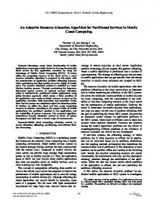
One of the platform that can be used for this purpose is OpenStack. The OpenStack is an open platform which creates and manages different Cloud infrastructures (public, private and hybrid) and provides network as a service using a module that called Neutron [2]. OpenStack consists of a set of building blocks which controls computing nodes, storage resources and networking devices in a datacenter. This platform includes a modular architecture as depicted in Figure 1.
Figure 1: Main blocks of the OpenStack platform. The responsibilities of these modules are in the following: 1. Compute module: this module is the main part of the IAAS which plays a controller role in Cloud computing and manages system resources. It also provides virtual machines and servers based on the users requests. 2. Swift module: this module stores the objects. Swift is a scalable storage system which stores unstructured data objects using Restfull http-based interface. 3. Cinder module: this module provides storage devices in block level permanently. 4. Horizon module: this module is the OpenStack dashboard which provides a GUI for users and administrators. 5. Keyston module: this module provides authentication and authorization services for other OpenStack services. 6. Galance module: this module stores and retrieves different disk images of virtual machines. 7. Neutron module: this module is an OpenStack network module that manages network and IP addresses. It also supports firewall, load balancer and virtual private network services.
3.2
XenServer Hypervisor
A hypervisor or virtual machine manager (VMM) is a part of hardware, firmware or software that creates and runs virtual machines. Hypervisors are categorized as following types [14]. 4
1. Type 1 hypervisor: these hypervisors are executed on the host’s hardware which controls and manages the guest operating systems. Oracle VM Server for SPARC, Oracle VM Server for x86, the Citrix XenServer, Microsoft’s Hyper-V, and VMware ESX/ESXi are known as type 1 hypervisor. 2. Type 2 hypervisor: these hypervisors are known as host hypervisors which execute similar to a program on a conventional operating system. VMware Workstation, VMware Player, VirtualBox and QEMU are examples of type 2 hypervisors. XenServer hypervisor is a type 2 hypervisor and provides the possibility of running one or multiple instances of different operating systems on a single host in parallel manner. XenServer hypervisor includes several elements [2]: XenServer hyperviosr, virtual machines, control domain (Dom0), console and toolstack.
3.3
OpenDayLight controller
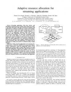
OpenDayLight is an open source project hosted by Linux foundation and implemented in Java [25]. The goal of this project is to accelerate the SDN approval and is supported by 40 different companies (Cisco, Juniper, IBM, ...). This controller includes multiple layers and the highest layer consists of networking applications. The middle layer is controller platform that provides a framework with different parts. This layer makes an abstraction of SDN and hosts Northbound e.g REST API and Southbound interfaces which used by different applications. The lowest layer includes the virtual and physical devices. The architecture of OpenDayLight is depicted in Figure 2.
Management GUI/CLI
D4A Protection
Network Applications Orchestration & Services
OpenDaylight APIs (REST) Base Network Service Functions Topology Mgr
Stats Mgr
Switch Mgr
FRM
Host Tracker
LISP Service
Affinity Service ARP Handler
Controller Platform
Service Abstraction Layer (SAL) (plug-in mgr., capability abstractions, flow programming, inventory, …) OpenFlow 1.0
1.3
NETCONF
OpenFlow Enabled Devices
OVSDB
SNMP
BGP
PCEP
LISP
Additional Virtual & Physical Devices
Open vSwitches
Southbound Interfaces & Protocol Plugins Data Plane Elements (Virtual Switches, Physical Device Interfaces)
VTN: Virtual Tenant Network, oDMC: open Dove Management Console, D4A: Defense4All protection, LISP: Locator/Identifier Separation Protocol OVSDB: Open vSwitch Data Base Protocol, BGP: Border Gateway Protocol, PCEP: Path Computation Element Communication Protocol, SNMP: Simple Network Management Block diagram of the OpenDayLight controller. (VTN: Virtual Tenant Network, Protocol
Figure 2: oDMC: open Dove Management Console, D4A: Defense4All protection, LISP: Locator/Identifier Separation Protocol, OVSDB: Open vSwitch Data Base Protocol, BGP: Border Gateway Protocol, PCEP: Path Computation Element Communication Protocol, SNMP: Simple Network Management Protocol)[25]. As depicted in Figure 2, this architecture consists of 3 layers. • Southbound protocols and plugins that organize lower layer. 5
• Network service functions that organize middle layer. • Network applications and northbound interfaces that organize the upper layer. The lowest layer or southbound protocols can support different protocols and plugins such as: OpenFlow 1.0, OpenFlow 1.3, BGP LS, LISP, SNMP, OVSDB, and NETCONF. The middle layer includes a set of management services such as topology manager, statistics manager, host tracker, inventory manager, forwarding rule manager and switch manager. The highest layer includes networking applications that controls and monitors the network behaviour.
4
The Proposed Approach
Regarding to the large volume of incoming flows into the network, a problem is related to find the optimized paths by the controller in SDN networks. If the controller has not enough resource to handle these requests, then a performance bottleneck is created. In this condition, to achieve the required performance and high scalability, improving performance of the controller by increasing the number of CPU cores in a linear order can be an useful solution. In this paper, the CPU and memory as main resources of the controller are allocated adaptively. In this Section, firstly, the integration of SDN and Cloud is presented then the allocation of resources to the SDN controller in an adaptive manner is described.
4.1
SDN and Cloud integration
In Cloud computing, the networking is seen as both a shared resource and as a part of the required infrastructure to share the other computing resources. On the other hand, similar to other infrastructures, network in Cloud computing to realize some of its requirements such as compatibility with the requirements of new applications, traffic behaviour management, scalability, and decreasing the manual configuration must be existed. This needs the advanced networking devices that without the network controller, the Cloud can not use the network resources in an efficient manner. The SDN using an abstraction layer with related API can overcome these problems. Therefore, the integration of the SDN and Cloud can prepare a powerful environment to provide the networking services. Both SDN and Cloud have similar three layer architectures, including: infrastructure, control and application layers. The SDN and Cloud can be integrated in three different ways. The first way is parallel execution of the SDN and Cloud stacks. However all applications can be executed in this architecture but it creates an overhead for the applications developers. On the other hand, the application must know the details of both SDN and Cloud which makes the complicated design and implementation of applications. The second way that overcomes disadvantages of the first way is to use a special control subsystem. This control subsystem can check the SDN devices directly. This way has also some disadvantages that limit extension of the SDN. The third way that is used in this work is to assume Cloud control system as an application in SDN. Figure 3 depicts this integrated architecture. In Figure 3, the Cloud control subsystem utilizes modules that translate the Cloud functions to the SDN functions. This system exploits the advantages of the second way and makes the extending of applications easier. This means that the developing of the SDN and Cloud infrastructures is possible separately. To implement the integration of the SDN and Cloud, the OpenStack platform and the OpenDayLight SDN controller is used. In the OpenStack, the Neutron module provides network as a service (NAAS) which includes a driver called ML2. ML2 transfers all the Neutron API calls related to the OpenDayLight SDN controller. The OpenDayLight SDN controller includes a Neutron API service that recognizes all data related to Neutron API calls and prepares them to other OpenDayLight services. Figure 4 depicts the execution flow of this process. 6
Application layer
Cloud applications
Cloud control/ Orchesteration
Computing/ storage servers
Control layer
SDN controler
Non-SDN network devices
SDN network devices
Infrastructure layer
SDN infrastructure Cloud infrastructure
Figure 3: Cloud and SDN integrated architecture. In Figure 4, inside the OpenDayLight the related request is sent to the Neutron service. This service executes related operations using southbound protocol plugins. The communication between Neutron service and protocol plugins is performed by Service Abstraction Layer (SAL). The southbound protocol plugins implement required communication protocols such as OpenFlow, and OVSDB for the dataplane. The OpenDayLight and OpenStack integration process is as follows. First, the XenServer hypervisor is installed on a raw physical host. XenServer can execute some number of virtual machines. One of main domains in XenServer hypervisor that is executed as a first virtual machine is DOM0. Other virtual machines are executed as DOMU or as the hosts. It is notable that a virtual machine in XenServer can be executed in either ParaVirtual (PV) or Hardware Virtual Machine (HVM) modes. The host domains that are executed in PV mode know about own virtualization and can communicate with DOM0 or XenServer directly, hence, have the better performance. The host domains that are executed in HVM mode do not know about their virtualization and hardware assumes that they are executed in real environment. After the XenServer hypervisor configuration, preparation required environment to integrate the OpenDayLight SDN controller and OpenStack platform includes the following steps. 1. Configuration of a virtual machine for OpenStack with all required modules: Kyston, Cinder, Swift, Glance, Neutron, and Compute. 2. Configuration of a virtual machine for OpenDayLight SDN controller. 3. Configuration of a separate virtual machine for execution of Compute module. 4. Configuration of a separate virtual machine for execution of Neutron module. After the configuration and installation of all modules, they should be tested with different situations. The integration and test of the OpenStack and OpenDayLight are summarized in the following steps. 1. Installation of the XenServer hypervisor. 2. Creation of the different virtual machines and their operating systems. 7
Neutron ML2 plugin ODL deriver
OpenDayLight REST API VTN provider
DOVE provider
Neutron REST API (extension)
OVSDB provider
Neutron service
Service Abstraction Layer (SAL) OVSDN plugin
Openflow 1.0 plugin
Openflow 1.3 plugin
OpenVswitch
Figure 4: OpenStack requests execution flow in the OpenDayLight SDN controller. 3. Installation of the OpenDayLight SDN controller and required modules OVSDB, VTN manager, and LISP to implement Neutron APIs. 4. Execution of the OpenDayLight SDN controller using related configuration. 5. Installation of the OpenStack with multinode option including controller node, compute node and network node. 6. Configuration of the OpenStack for integration with the OpenDayLight controller. 7. Creation and addition of different virtual machines from the OpenStack platform. 8. Confirmation and observation of same topology in the OpenStack platform. Figure 5 depicts the basic architecture of required environment that has been implemented in this paper. As it can be observed in Figure 5, the XenServer is used as a hypervisor to create the required virtual machines and SDN controller.
4.2
Adaptive resource allocation in SDN controller
Two important challenges in the SDN controller design are performance improvement and scalability. At the same time, resource usage optimization is a main problem in the virtual environments. For this purpose, a service has been designed that based on the traffic load in the SDN controller can allocate different resources such as CPU and memory to the SDN controller or release these resources when they are not need. To improve the performance of controller and preventing of performance bottleneck of the SDN controller, the required resources must be allocated, when the traffic load is being increasing. On the other hand, when the traffic load to optimize resource usage is decreased, the extra resources must be released. When a physical host that XenServer hypervisor is executed on it, the whole memory by default is allocated to DOM0, then 8
Domain0 VM
OpenStack Xapi plugin Xapi
OpenStack VM Compute VM Network VM OpenDayLight (Neutron) (DevStack withPV kernel) VM Compute
OpenStack
Networking ML2 Plugin
Neutron REST API
Networking ML2 Plugin
OpenVswitch
OpenDayLight REST API
etc...
etc..
etc...
OpenVswitch
Nova-Compute
Keystone
Horizon
Glance
XenAPI
etc...
OpenStack uses XenAPI python module to communicate with DOM0
Core Component
Figure 5: Basic architecture of required environment. this memory is allocated to other created and executed virtual machines. In the XenServer hypervisor, after the definition of a virtual machine and the initial allocation of required resources, it is possible to change these resources dynamically. If the virtual machine is executed in the HVM virtualization mode, there is no way to communicate between the hypervisor and the virtualized kernel resulting hypervisor can not change the current allocated memory. While the virtual machine is executed in the PV virtualized mode, the XenServer hypervisor can change dynamically the allocated memory. It should be noted that in this condition, a minimum memory (512MB) for the DOM0 must be remained. This is because, if DOM0 crashes or does not execute, then the hypervisor could not operate and memory could not be allocated. Dynamic memory management in the XenServer hypervisor is done by a special memory management unit called DMC. It is notable that this feature is existed in the XenServer hypervisor 5.6 and later. Similar to the memory, the number of allocated CPUs to a virtual machine can be managed dynamically. When a XenServer hypervisor is installed each physical CPU (CPU core) is abstracted as a virtual CPU that divides CPU cycles for each core and multiple virtual machines are allowed to access a physical core by time sharing. This means that if the number of virtual machines that uses a single shared virtual CPU is increased, less CPU cycles can be used by each virtual machine. All VCPUs are managed by a local queue on a physical CPU. This queue is ordered based on the priority of the VCPUs. Each VCPU receives a fair amount of CPU resources. Manager administrates the priorities by changing the values of CAP and Weight parameters. Weight parameter is to determine the number of cycles that a domain or a virtual machine can receive and its value is a relative value. As an example, a VCPU with the weight=128 can receive two times cycles in comparison to a VCPU with the weight=64. The next parameter is the CAP that determines the maximum usage rate of CPU cycles by a domain. The CAP parameter is absolute value. As an example, if a CAP value for a VCPU is 100 that means this VCPU may use 100% CPU cycles of a physical host. Using this concept, the adaptive allocation of resources by the XenServer has been implemented. The architecture of adaptive resource allocation is depicted in Figure 6. In this architecture, three steps is performed as follows. 9
ADAPTIVE RESOURCE ALLOCATION FOR SOFTWARE DEFINED NETWORKING CONTROLLERS Resource adaptation decisions Scale up/ scale down
9
Resource adaptation decisions Scale up/ scale down Action: - Allocate more resources - Take additional resources
Load measurement (Resource utilization)
APP1
Action: - Allocate more resources - Take additional resources
Load measurement (Resource utilization) APP2 APPn
SDN controller APP1 SW1
SW2
APP2
APPn
SW3 SDN controller
SW1
SW2
Figure 6: Proposed architecture for adaptive resource allocation.
SW3
1. Load measurement by regular monitoring at the particular time slots. Figure 6. Proposed architecture for adaptive resource allocation. 2. Decision making and investigation to suffice of current allocated resources to the SDN controller. These steps are presented in Algorithm 1. This algorithm, investigates the amount of resources in 3. Allocation or releasing of resources based on the condition of the previous step. the SDN controller using a Get RRD() function and performs related operations to allocate/release theFigure resources. These steps are presented in 7. This algorithm, investigates the amount of resources in the SDN controller using a Get RRD() function and performs related operations to allocate/release the resources. Algorithm 1: The resource allocation algorithm. while true do Get RRD(); if Checkresizing() then DoResizing(); Wait(10);
7: The resource allocation algorithm. InFigure this algorithm, Get RRD() function after the receiving the information related to the resource usage, measures the load. The CheckResizing function checks the usage, allocation/releasing of the In this algorithm, Get RRD() function after the receiving the information related to the resource resources based on the value of threshold. DoResizing function performs allocation/releasing of measures the load. The CheckResizing function checks the allocation/releasing of the resources based on the resources. In each iteration, some resources must be allocated or released. the value of threshold. DoResizing function performs allocation/releasing of the resources. In each iteration, At the end of each iteration, It waits for mentioned functions are checked. Subsequently, the details some resources must be allocated or released. At10 theseconds end of and eachthen iteration, It waits for 10 Seconds and then of each function are investigated. mentioned functions are checked. Subsequently, the details of each function is investigated.
4.2.1. Load measurement In this approach, to measure the load (amount of consumed resources) Load measurement the Round Robin database service of XenServer is used. This database stores the data related theload consumed This database,thesaves information and statistics In this approach, to measuretothe (amountresources. of consumed resources) Round Robin database service ofof this host and other machines this host. of information in this database the XenServer is used. Thisguest database stores hosted the databy related to theSome consumed resources.stored This database saves are total allocated memory, utilization of VCPUs, etc. This the information and statistics of this free host internal and othermemory, guest machines hosted by this host. Someinformation informationcan be received using an HTTP call as a XML file. For example, the following URL, can be used to receive an updated information of all executed VMs on a physical host. 10 http://user:password@host/rrd_updates?start=&interval= 4.2.1
This request receives updated information of all VMs on a physical host from time ”start =< secondsseinceepoch > ” for interval ”interval =< seconds > ”. As mentioned before, this information is received as a disorder XML file that is not easy to read and interpret. Therefore, to extract the related information and organize them as a table a parser has been designed. The Load measurement algorithm is depicted in Algorithm 2.
stored in this database are: total allocated memory, free internal memory, utilization of VCPUs, etc. This information can be received using an HTTP call as an XML file. For example, the following URL, can be used to receive an updated information of all executed VMs on a physical host. http://user:password@host/rrd_updates?start= &interval=
This request receives updated information of all VMs on a physical host from time ”start =< secondsseinceepoch > ” for interval ”interval =< seconds > ”. As mentioned before, this information is received as an unordered XML file that is not easy to read and interpret. Therefore, to extract the related information and organize them as a table, a parser has been designed. The Load measurement algorithm is depicted in Figure 8. In this algorithm to measure the load Algorithm 2: Load measurement algorithm. to receive the updated information must b Procedure Get RRD() S tartT ime ← CurrentT ime − T imer; purpose, the current time is decreased fro HT T PRequest(); a timer that shows time slot of receiving t return XML f ile; On the other hand, using this method am T ableR ← XMLParser(); source between current time and time me for all CPU s of V M do Pn CPUi termined. Subsequently, to measure the Avg CPU usage o f V M ← i=1 n ; that a VM may use several VCPU, the return Avg CPU usage o f V M; computed as average usage of all VCPUs return V M CPU num; P V M mem usage ← T otal − internal memory f ree; All di return V M mem usage; Average CPU usage o f V M = Nu
Figure 8: Load measurement algorithm.
It is also, to compute the consumed mem memory is subtracted from total memory
Consumed memory = T otal memory In this algorithm to measure the load, first the starting time to receive the updated information must be determined. For this purpose, a specified time by a timer that shows time slot of receiving4.2.2. time inResource the RDDallocation/releasing deci database is decreased from the current time. On the other hand, using this method determines Algorithm amount of the ?? presents the decision me consumed resources between current time and time measured by the timer. Subsequently, measure the of to resources. load, due to this fact that a VM may use several VCPU, the CPU usage of VM is computed as the average Algorithm 3: CheckResizing algorithm. usage of all VCPUs as: P Procedure CheckResizing() All di f f erent CPU s usage T ableR.Get Average CPU usage o f V M = (1)avg CPU usage o f V M ; T ableR.Get V M CPU num ; Number o f CPU s T ableR.Get V M mem usage;
T ableR.Get V M mem total; Also, to compute the consumed memory of VM, the free memory is subtracted from total memory.
Consumed memory = T otal memory − Free memory 4.2.2
Resource allocation/releasing decision
if avg CPU usage o f V M > CPU high V M (2) CPU num + +; else if avg CPU usage o f V M < CPU V M mem num − −; if V M mem usage > mem high T HR the V M mem T otal ← V M mem total ∗ else if V M mem usage < mem low T HR T otal V M mem T otal ← V M mem 2 is received
Figure 9 presents the decision method to allocate/release of resources. As it can be observed in this Algorithm, first different values related to the resource usage from the table TableR and then based on these values required decision is performed. Subsequently, a maximum and minimum threshold values to make the decision for resource changing is performed. The distance between the maximum and minimum thresholds should be large enough because of the periodic As it can be observed in this Algorithm related to the resource usage is received 11 and then based on these values required d Subsequently, a maximum and minimum make the decision for resource changing tance between maximum and minimum large enough because of periodic changin vention. After the investigation of amo if the changing conditions (based on th confirmed then related operation to incr CPUs or memory (DoResizing function) changing is as follows. The number of C
It is also, to compute the consumed memory of VM, the free memory is subtracted from total memory. Consumed memory = T otal memory − Free memory (2) 4.2.2. Resource allocation/releasing decision Algorithm 3 presents the decision method to allocate/release of resources. Algorithm 3: CheckResizing algorithm. Procedure CheckResizing() T ableR.Get avg CPU usage o f V M ; T ableR.Get V M CPU num ; T ableR.Get V M mem usage; T ableR.Get V M mem total; if avg CPU usage o f V M > CPU high T HR then V M CPU num + +; else if avg CPU usage o f V M < CPU low then V M mem num − −; if V M mem usage > mem high T HR then V M mem T otal ← V M mem total ∗ 2 else if V M mem usage < mem low T HR then T otal V M mem T otal ← V M mem 2
As it Figure can be9:observed in this algorithm. Algorithm, first different values related to the resource usage is CheckResizing received from the sorted tables and then based on these values required decision is performed. Subsequently, a maximum and minimum threshold values to make the decision for resource changing and oscillation prevention. After the investigation of amount of resource usage if the changing changing is performed. The distance between the maximum and minimum thresholds should be conditions (based on the threshold values) is confirmed, then the related operation to increase and decrease large enough becauseALLOCATION of periodic changing and oscillation prevention. After the investigation ADAPTIVE RESOURCE FOR SOFTWARE NETWORKING CONTROLLERS 11of the of CPUs or memory (DoResizing is done. The resource changing isDEFINED as follows. of amountfunction) of resource usage if the changing conditions (based onThe the number threshold values) is confirmed, CPUs is increased linearly, because of performance of the SDN controller can be increased by changing the then related operation to increase and decrease of CPUs or memory (DoResizing function) is done. number of CPUs. In the case of memory, both coarse(256 fine methods canthe used. In the fine grainstep memory are increased/decreased gradually MB grain in each step). In coarse in each The resource changing is and as follows. The number ofbeCPUs isgrain, increased linearly, because of the method, memory is increased/decreased gradually (256ToMB in each step).reliability In the coarse grain, in is each stepthis is because if increased/decreased two times. achieve higher coarse grain used, performance of SDN controller can be increased by changing the number of CPUs. In the case memory is increased/decreased twomemory times. To achieve higher reliability, coarse the approachwill is used, the required the SDN controller ismethods not the sufficient controller be crashed. It should of memory, bothforcoarse and fine grain can begrain used. In the fine grain method, memory is this is because if the required the SDNand controller is not sufficient, theCPU controller will be crashed. be notedmemory that thefor maximum minimum values for the and memory to be assumed. It should be noted that the maximum cand minimum values for the CPU and memory to be assumed. Copyright 2016 John Wiley & Sons, Ltd. Int. J. Commun. Syst. (2016) using dacauth.cls DOI: 10.1002/dac 4.2.3.Prepared Resource changing This step is the last part of the our designed service that is depicted in 4.2.3 Resource changing Algorithm 4.
This step is the last part of the our designed service that is depicted in Figure 10. Algorithm 4: DoResizing algorithm. Procedure CheckResizing() S S H(EXECUT E COMMAND f or change V M CPU num); S S H(EXECUT E COMMAND f or change V M mem T otal); End Procedure
The ResizingFigure algorithm tries to control the resource usage between the maximum and minimum 10: DoResizing algorithm. thresholds. Each call of Resizing procedure may either increase/decrease the resources or without The Resizing algorithm tries to control the resource usage between the maximum and minimum threshany changes. The operations related to the increasing of resources are more important than olds. Each call of the Resizing procedure may either increase/decrease the resources or without any changes. decreasing, this is because, when the resource usage is more than the threshold, performance of The operations related to the increasing of resources are more important than decreasing, this is because, SDN controller is decreased. For example, the packet processing delay may be increased with when the resource usage is more than the threshold, performance of SDN controller is decreased. For exthe CPU shortage, or memory shortage may be causing the controller crashed and issue of out of ample, the packet processing delay may be increased with the CPU shortage, or memory shortage may be memory message. While the resource usage is less than the threshold, there is not a problem with the caused the crashing of controller and issues of out of memory message. While the resource usage is less controller performance. The only problem in this case is the utilization of resources. To execute the than the threshold, there is not a problem with the controller performance. The only problem in this case is related commands to change the resources an SSH service was implemented that communicates to the utilization of resources. To execute the related commands to change the resources, an SSH service was the hypervisor and transfers the commands by our designed service to the hypervisor. The hypervisor implemented that communicates to the hypervisor and transfers the commands by our designed service to executes related operations to change the resources. The state diagram of the adaptive resource controller service is depicted in Figure 7. SDN agent
12 Resource usage values
RRDfile.xml
HTTP req Read RRD
Parser
Check resource usage No operation
Scale up/down command
the hypervisor. The hypervisor executes related operations to change the resources. The state diagram of the adaptive resource controller service is depicted in Figure 11. SDN agent
Resource usage values
RRDfile.xml
HTTP req Read RRD
Parser
Check resource usage No operation
Scale up/down command Timer
SSH manager
Hypervisor
Figure 11: State diagram of the adaptive resource controller service. As it can be observed in Figure 11, the SDN agent as an adaptive resource allocation service requests statistical data related to the resource usage from the RDD database using an HTTP request. In the next step, the related data as an XML file is received, then, for sorting and analysis of these data a parser is used. The parser sorts data as a table and the required data is sent to a function in the decision step. In the decision step, conditions related to the resource usage are investigated and related operation as scale up/down commands is sent to SSH manager. The SSH manager sends resource changing commands to the hypervisor for changing the resources. In this step, it is possible no change in the resources that is shown by No operation in the state diagram. After these steps, the timer goes to wait for a particular duration and then mentioned steps is repeated. 4.2.4
A discussion on resource allocation/ releasing
In the XenServer 5.6 and later, after the creation of virtual machine and determining amount of the resources, changing of the resources is possible in a dynamic manner. The XenServer uses a special management system that called DMC to change the memory dynamically. This system can be used to change the allocated memory for a VM if the created VM is in PV mode. In the CPU case, administrator can determine the maximum number of VCPUs (32 VCPUs) that can be allocated to a VM then after the booting of VM the number of VCPUs can be increased to maximum value. Actually, admin based on the information of available resources determines that how much of these resources can be used by particular VM. It should be noted that these cases do not need the rebooting of the VM. As mentioned before, we have focused the changing of resources without rebooting of the VM that is performed by XenServer. A challenge in the VM migration is related to the working method of networking section. While in this paper the networking section is working with the existing VCPU and simultaneously the number of VCPUs is being increasing. To change the number of VCPUs related to the VM, following script is used. 13
xe vm-vcpu-hotplug new-vcpus= uuid= The increasing/ decreasing of the resources is based on the threshold value. It should be noted in the decreasing of resources case, the rescheduling is not preemptive and the packet processing tasks do not need to be rescheduled. This means that the tasks are packet processing functions with the small processing time which are processed quickly. When the load is decreased the idle VCPUs is released or the packets that are forwarded to CPU with the low load is redirected to the other VCPUs without any rescheduling. It should be noted, in this paper, the approach has been implemented and evaluated based on XenServer. The mapping of VCPU to the physical CPUs are possible in all hypervisors e.g. KVM, VMware and Hyperv. For example, in KVM hypervisor to change the number of VCPUs related to the VM following script is used. virsh setvcpus --config For others hypervisors there are similar scripts. In addition, the system will be evaluated based on the networking load which are generated by Cbench and Mininet. The Cbench and Mininet are used to evaluate the OpenDaylight controller which is executed on the OpenStack platform. This means that the OpenStack and other modules are evaluated indirectly. In overall, as it can be observed that the communication between OpenStack and OpenDaylight, the OpenDayLight has been replaced with the Compute node in OpnStack and performs network operations in Cloud environment. This replacement improves the scalability, programmability and flexibility of the OpenDayLight SDN controller.
5
Empirical Evaluation
In this Section, proposed adaptive resource allocation service is evaluated. For this purpose, the performance, memory consumption and CPU usage are evaluated. For these evaluations, networks with different number of switches and the tree topology are investigated. The software and hardware specifications is presented in Table 1. Physical Server type Proessor model 8 CPUs x 3.166 GHz 16GB PC2-5300F XenServer 6.5 SP1 OpenDayLight Helium
HP Proliant DL 380 G5 R Xeon R CPU X5460 α3.16GHz Intel Number of CPU cores Total memory Hypervisor SDN controller
Table 1: The Software and hardware specifications. Two tools used in this paper are Mininet [19] and Cbench [28]. The Mininet is used to evaluate the memory and CPU usage and Cbench is used to evaluate the performance (latency) of the controller. The Mininet can create a network of the OpenVSwitchs with different sizes using tree topology quickly and these topologies can transfer to a real environment directly. Cbench works similar to the Mininet. It simulates the OpenVSwitchs and sends the packet-in messages to the SDN controller and operates in the latency and throughput modes.
14
5.1
Resources usage evaluation
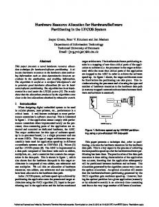
To evaluate the resource usage, different switches and several experiments are tested. The used topology in this evaluation is tree topology that is one of popular topology in datacenters. For example following command in the Mininet command line creates a topology including 7 switches and 8 hosts. Where switches communicate to a controller with the mention IP address via port 6633. sudo mn --controller=remote,ip= --topo tree,3 OpenDayLight controller includes a network application that is called Simple forwarding. Simple forwarding allows to use a basic forwarding service that creates decisions related to the packet transferring and inserts related flows in the forwarding table of the network devices. Therefore, this application is used to evaluate the resource usage in topologies with different switches. The steps to evaluate the CPU and memory usage are as follows. 1. Creation of a topology with 7 switches and 8 connected hosts using the Mininet command line. 2. Investigation of the topology creation confirmation using an OpenDayLight SDN controller GUI. 3. Execution of the simple forwarding application using the OpenDayLight SDN controller console. 4. Execution of the pingall command using Mininet command line (to test the reachability of pair of machines). 5. Investigation of the flows creation confirmation and the machine learning. 6. Evaluation of the CPU and memory usage. 7. Repetition of the previous steps with increasing number of the switches (15, 32, ...). Figure 12 and Table 2 depict CPU usage for different number of switches.
CPU usage (%)
100
CPU0
CPU1
CPU2
CPU3
80 60 40 20 0 7
15
31 63 127 Number of switches
255
511
Figure 12: Amount of CPU usage of the OpenDayLight SDN controller for the different number of switches. As it can be observed in Figure 12 and Table 2, the number and usage of CPUs for different number of switches are different. For example, when the number of switches in the topology is 31 and tree topology is used, the number of used CPU is 1 and CPU usage is 76.32 %. The threshold value has been set to 85%, 15
Switches CPU0 (%) CPU1 (%) CPU2 (%) CPU3 (%)
7 15.69 0 0 0
15 45.57 0 0 0
31 76.32 0 0 0
63 71.41 77.53 0 0
127 61.45 73.22 67.11 0
255 91.23 78.22 81.32 0
511 77.65 68.22 79.05 69.3
Table 2: CPU usage of the OpenDaylight SDN controller for the different number of switches. therefore, the number of used CPU is remained at 1. When the number of switches are increased to 63, the CPU load is also increased and the number of used CPUs growth into 2. In this case, CPU0 and CPU 1 with different amount of usage are used. This procedure is similar for 127 switches and CPU0, CPU1 and CPU2 are used. As mentioned previously, changing in the number of CPUs is occurred when the average usage of all used CPUs is more than the threshold. For example, for 255 switches, the average usage of CPUs is 91.23+78.22+81.32 = 83.59% which is lees than the default threshold 85%, therefore in this case, the number of 3 CPUs is not changed. Figure 13 depicts the memory usage for the different number of switches.
Memory usage (MB)
5000 4000 3000 2000 1000 0 7
15
31 63 127 Number of switches
255
511
Figure 13: Amount of memory usage of the OpenDayLight SDN controller for the different number of switches. As it can be observed in Figure 13, increasing the number of switches increases the memory usage of the SDN controller. When the number of switches is less than 31, the memory usage is increased slowly. When the number of switches are more than 31 the memory usage is quicker and the slope of the changes is severe. In the overall, the memory usage when all 511 switches are working in comparison to the 7 switches is 3912 1807 = 2.15 times.
5.2
Throughput and delay evaluation
As mentioned before, the Cbench works in two latency and throughput modes. Controller latency means that how much time it takes to process a single packet by the controller? In this mode, Cbench sends a single packet from a switch to the SDN controller and waits to receive the response and after the receiving response sends another request. To evaluate the latency, the SDN controller with the related configuration is configured, then the required instructions in Cbench console are executed and finally the latency is measured. Figure 14 depicts the latency evaluation of the OpenDayLight SDN controller with the different number of switches. As it can be observed in Figure 14, in 4 switches case 5999.36 responses/Sec is generated by the SDN 16
Thousands
Response/sec
50 40 30 20 10 0 4
8
16 32 Number of switches
64
128
Figure 14: The OpenDayLight SDN controller throughput in the latency mode.
Thousands
Response/sec
controller in average. This means that for each switch 1499 responses/Sec is generated. When the number of switches is increasing the number of responses/Sec is also increased. For example, from 5999.36 responses/Sec for 4 switches is increased to 10767.24 responses/Sec for 8 switches. It should be noted that when the number of switches is increasing the number of responses/Sec per switch is decreased. For example, in 4 switches case, the responses per switch is 1499, while it is 1345 responses/Sec per switch for 8 switches case. Figure 15 depicts the throughput of the controller in throughput mode. In this mode the controller is evaluated for the number of processed packets per Seconds. For this purpose, Cbench generates a huge traffic and sends to the controller and records the total number of received responses then computes the number of received responses per Seconds as the throughput of the controller. Therefore, the throughput is defined as maximum number of flows that controller can handle in the heavy traffic condition. As it can 60 50 40 30 20 10 0 4
8
16 32 Number of switches
64
128
Figure 15: The OpenDayLight SDN controller throughput in the throughput mode. be observed in Figure 15, in 4 switches case in average 52368.78 responses/Sec is generated that means 13092 responses/Sec for each switch is received by the SDN controller. For 8 switches case, in average 50718.39 responses/Sec is generated that also means 1650 responses for each switch is received. Based on these results, total number of responses for 8 switches are less than 4 switches. In 16, 32, 64 and 128 switches cases the decreasing rate in number of responses/Sec is larger. For example, in 64 switches case,
17
233 responses for each switch is generated. Therefore, the throughput of the controller is decreased when the number of switches is increased. This is because, increasing the number of switches increases the number of interrupts in the OpenDayLight SDN controller, and increasing the number of interrupts in the SDN controller decreases the number of handled responses by the SDN controller.
6
Conclusions
An SDN controller is a fundamental component of an SDN network. Therefore, designing of the controller in an optimized way to improve the performance is a main challenge in the SDN. In this paper, an adaptive service to increase/ release the resources (CPU and memory) to improve the performance of the SDN controller was designed. The main reason to design of this service is because of migration of virtual machines to make an adaptive and scalable SDN controller has some problems such as flow consistency, and migration overheads. However, the proposed service can be used in the migration option in the Cloud systems and makes more efficient these systems because of the preventing of unnecessary migrations. This service has been implemented using XenServer hypervisor, OpenStack and OpenDayLight as a distributed SDN controller. Based on the achieved results, the worries on resource limitations of the SDN controllers as a key component in SDN can be overcome. The implementation results show that the increasing number of the flows causes the growth in the number of CPU cores and memory linearly. To make more efficient this system, the other networking resources such as network bandwidth can be added to the service. The proposed service can be used in other Cloud and distributed computing systems as a public service. In addition, this approach can be tested and evaluated using other hypervisors like KVM, Hyperv and VMware.
References [1] http://www.projectfloodlight.org/floodlight/, April 2016. [2] Xenserver: Open source virtualization platform. http://xenserver.org/, 4 2016. [3] Tootoonchian A, and Ganjali Y. Hyperflow: A distributed control plane for openFlow. In Proceedings of the 2010 Internet Network Management Conference on Research on Enterprise Networking, INM/WREN’10, pages 3–9, 2010. [4] Shaikh A, Tracey J, Banikazemi M, Olshefski D, and Wang G. Meridian: an sdn platform for cloud network services. IEEE Communications Magazine, 51(2):120–127, February 2013. [5] Belhaj H H, Basta A, Blenk A, and Kellerer W. Towards a dynamic sdn virtualization layer: Control path migration protocol. In Network and Service Management (CNSM), 2015 11th International Conference on, pages 354–359, 2015. [6] Hart J, Higuchi Y, Kobayashi M, Koide T, Lantz B, O’Connor B, Radoslavov P, Snow W, Berde P, Gerola M, and Parulkar G. Onos: Towards an open, distributed sdn os. In Proceedings of the Third Workshop on Hot Topics in Software Defined Networking, HotSDN ’14, pages 1–6, 2014. [7] Ramos F M V, Botelho F, Bessani A, and Ferreira P. On the design of practical fault-tolerant sdn controllers. In 2014 Third European Workshop on Software Defined Networks, pages 73–78, September 2014.
18
[8] Cox A L, Cai Zh, and Eugene T. S. Maestro: a system for scalable OpenFlow control. Technical report, Department of Computer science, rice University, 2010. [9] Erickson D. The beacon OpenFlow controller. In Proceedings of the Second ACM SIGCOMM Workshop on Hot Topics in Software Defined Networking, HotSDN ’13, pages 13–18, 2013. [10] Mukherjee S, Lakshman T V, Dixit A A, Hao F, and Kompella R. Elasticon: An elastic distributed sdn controller. In Proceedings of the Tenth ACM/IEEE Symposium on Architectures for Networking and Communications Systems, ANCS ’14, pages 17–28, 2014. [11] Liang Ch, Fonseca R, Ferguson A D, Guha A, and Krishnamurthi Sh. Participatory networking: An api for application control of sdns. SIGCOMM Computer Communication Review, 43(4):327–338, 2013. [12] Monaco M, Keller E, Caesar M, Rexford J, Ghorbani S, Schlesinger C, and Walker D. Transparent, live migration of a software-defined network. In Proceedings of the ACM Symposium on Cloud Computing, SOCC ’14, pages 1–14, 2014. [13] Pettit J, Pfaff B, Casado M, McKeown N, Gude N, Koponen T, and Shenker S. Nox: Towards an operating system for networks. SIGCOMM Computer Communication Review, 38(3):105–110, 2008. [14] Popek G J, and Goldberg R. P. Formal requirements for virtualizable third generation architectures. Communication ACM, 17(7):412–421, July 1974. [15] Madi T, Jarraya Y, and Debbabi M. A survey and a layered taxonomy of software-defined networking. IEEE Communications Surveys Tutorials, 16(4):1955–1980, 2014. [16] Zhiyao H, Ting Q, Junjie X, Deke G, and Pin L. Control plane of software defined networks: A survey. Computer Communications, 67:1–10, 2015. [17] Morita K. Ryu network operating system. https://events.linuxfoundation.org/images/stories/pdf/lcjp2012 kazutaka.pdf, June 2012. [18] Gude N, Stribling J, Poutievski L, Zhu M, Ramanathan R, Iwata Y, Inoue H, Hama T, Koponen T, Casado M, and Shenker S. Onix: A distributed control platform for large-scale production networks. In Proceedings of the 9th USENIX Conference on Operating Systems Design and Implementation, OSDI’10, pages 351–364, 2010. [19] Heller B, Lantz B, and McKeown N. A network in a laptop: Rapid prototyping for software-defined networks. In Proceedings of the 9th ACM SIGCOMM Workshop on Hot Topics in Networks, Hotnets-IX, pages 6–13, 2010. [20] Sanchez D, Matias J, Jacob E, and Demchenko Y. An OpenFlow based network virtualization framework for the cloud. In Cloud Computing Technology and Science (CloudCom), 2011 IEEE Third International Conference on, pages 672–678, November 2011. [21] Hitz S, Matsumoto S, and Perrig A. Fleet: Defending sdns from malicious administrators. In Proceedings of the Third Workshop on Hot Topics in Software Defined Networking, HotSDN ’14, pages 103–108, 2014. [22] Balakrishnan H, Parulkar G, Peterson L, Rexford J, Shenker S, McKeown N, Anderson T, and Turner J. OpenFlow: Enabling innovation in campus networks. SIGCOMM Computer Communication Review., 38(2):69–74, March, 2008. 19
[23] Michel O, Monaco M, and Keller E. Applying operating system principles to sdn controller design. In Proceedings of the Twelfth ACM Workshop on Hot Topics in Networks, HotNets-XII, pages 1–7, 2013. [24] Dashtbani M, Nikbazm R, and Ahmadi M. Enabling SDN on a special deployment of OpenStack. In Computer and Knowledge Engineering (ICCKE), 2015 5th International Conference on, pages 337– 342, October 2015. [25] OpenDayLight. OpenDayLight platform architecture. https://www.opendaylight.org/lithium, 4 2016. [26] Black C, Goransson P. Software Defined Networks: A Comprehensive Approach. Morgan Kaufmann Publishers Inc., 2014. [27] Bouet M, Phemius K, and Leguay J. Disco: Distributed multi-domain sdn controllers. In 2014 IEEE Network Operations and Management Symposium (NOMS), pages 1–4, May 2014. [28] Sherwood R, and Yap K. K. http://archive.openflow.org/wk/index.php/Oflops, 2011.
Cbench
controller
benchmarker.
[29] Chouhan P K, Fraser B, Lake D, Finnegan J, Viljoen N, Miller M, Sezer S, Scott-Hayward S, and Rao N. Are we ready for sdn? implementation challenges for software-defined networks. IEEE Communications Magazine, 51(7):36–43, July 2013. [30] Lee T, Lee S, Chung J, Porras P, Yegneswaran Y, Noh J, Shin S, Song Y, and Kang B. B. Rosemary: A robust, secure, and high-performance network operating system. In Proceedings of the 2014 ACM SIGSAC Conference on Computer and Communications Security, CCS ’14, pages 78–89, 2014. [31] Ganjali Y, Casado M, Tootoonchian A, Gorbunov S, and Sherwood R. On controller performance in software-defined networks. In Proceedings of the 2Nd USENIX Conference on Hot Topics in Management of Internet, Cloud, and Enterprise Networks and Services, Hot-ICE’12, pages 10–20, 2012. [32] Clayman S, Pavlou G, Tuncer D, Charalambides M. Adaptive resource management and control in software defined networks. IEEE Transactions on Network and Service Management, 12(1):18–33, March 2015. [33] Takamiya Y, and Karanatsios N. Trema OpenFlow controller framework, 2012.
20