Adaptive Resource Allocation in Cellular OFDMA ... With the frequency reuse mentioned above, the ..... as MultipleâRS Adaptive Activation (MRAA) algorithm.
Adaptive Resource Allocation in Cellular OFDMA System with Multiple Relay Stations Megumi Kaneko and Petar Popovski Department of Electronic Systems, Aalborg University Niels Jernes Vej 12, DK-9220 Aalborg, Denmark Email: {mek|petarp}@kom.aau.dk
Abstract— We address the problem of radio resource allocation in the Downlink (DL) of a cellular system with Relay Stations (RS), based on Orthogonal Frequency Division Multiple Access (OFDMA) transmission technology. There is a need for the design of resource allocation algorithms for this type of system, where practical yet efficient algorithms are required to exploit the potential capacity and coverage increase offered by the relays. We propose several resource allocation algorithms with different options such as time or frequency division. The evaluations give some directions about the suitable allocation schemes. One algorithm offers an overall improvement of throughput and coverage, compared to a system without relays. At the same time, the advantage of our algorithms is that their complexity and amount of information overhead are much reduced compared to an optimal algorithm.
I. I NTRODUCTION In the future 4th Generation (4G) wireless system, it is highly expected that high data rates will be accessible over large areas. By deploying Relay Stations (RS) in a cellular system, it becomes possible to forward high data rates in remote areas of the cell while keeping a low cost of infrastructure. To exploit this potential gain in capacity and coverage, an adequate and practical radio resource allocation strategy should be designed. Hence, the problem of resource allocation and scheduling for relay–aided cellular systems has been a flourishing topic for investigation and has produced a number of works such as [1] [2] [3]. However, in these works, an OFDM physical layer is not considered. By combining RS resource allocation with OFDMA, even higher capacity and cell coverage can be expected. Some works on resource allocation for OFDMA relay systems can be found in the literature [4] [5], but to the best of the authors’ knowledge, there has been little work in the literature on specific resource allocation schemes for multiple access in a RS–aided cellular system based on OFDMA technology. Thus, our goal is to provide efficient allocation algorithms for that system to enable a high capacity and high coverage. Also, one of the key points is that the algorithms are designed in such a way that reduces the algorithm complexity and required amount of Channel State Information (CSI).
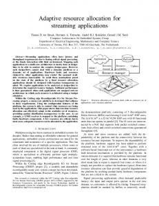
(RS) in a single cell 1 , where users feed back to the BS their Channel State Information (CSI) on every subchannel, defined as a group of adjacent subcarriers. Discrete Adaptive Modulation and Coding (AMC) model from Table I is applied per subchannel, for each user. The BS is surrounded by multiple RS, as depicted in Fig. 1. The RS are placed at a distance of 0.8km from the BS, where the cell radius is 1km. Two categories of frame structures are considered: • Time division between BS and each RS transmissions, with TBS the time allocated to the BS–subframe where transmissions from the BS occur, and TRS allocated to each RS–subframe where transmissions from the RS occur. Time division is widely considered in the 802.16– based relay system [6]. Since the interference between opposite RS can be assumed low, they are allocated the same subframe in a parallel manner, as shown in Fig. 2. There are 3 groups of opposite RS: pairs (RS1 , RS4 ), (RS2 , RS5 ) and (RS3 , RS6 ). • Frequency division: each RS is served a certain frequency region. With the frequency reuse mentioned above, the structure is shown in Fig. 3. Moreover, the following assumptions are taken: • Inside the BS–subframe, BS–MS or direct transmissions, and BS–RS or feeder transmissions, are divided in frequency, where each subchannel can be allocated to either link. To the best of our knowledge, this is a new type of structure as usually, the frequency regions for BS–MS and for BS–RS are fixed and separated. • TBS and TRS can be adapted from frame to frame. The algorithms are optimized for the two–hop scenario. With this frame structure, the packets of a relayed user queued at the BS will require at least two frames to arrive to destination: with the first frame, the packets are sent from BS to RS; in the second frame, from RS to MS. TABLE I D ISCRETE AMC M ODEL Modulation Rate [b/symbol] SNR Threshold [dB]
BPSK 1
4-QAM 2
16-QAM 4
64-QAM 6
256-QAM 8
−5
13.6
20.6
26.8
32.9
II. S YSTEM M ODEL We focus on the Downlink (DL) transmissions from a Base Station (BS) to Mobile Stations (MS) or Relay Stations
1550-2252/$25.00 ©2007 IEEE
3026
1 Here the interference from adjacent cells is not included, but may be incorporated in the noise.
We assume here that each MS is attached to one access point at a time, among the BS and the RS. In the optimal allocation, the path selection and the subchannel/time allocation should be made simultaneously in a BS–centralized manner. Since our goal is to provide low complexity algorithms which require only a reduced amount of CSI, we consider that the path selection is performed first, based on the long–term average user SNR, as done in [2]. The achievable AMC levels corresponding to the long–term average SNR of the direct and relayed links are compared for each user, and the path allowing the best achievable rate is chosen. The subchannel/time allocation is made after each user is linked to a path.
RS6
RS5
RS1
BS
RS4
RS2
RS3
Direct link Relayed link
Fig. 1.
Cellular System with Multiple Relays
III. R ESOURCE A LLOCATION A LGORITHMS We propose a RS–aided centralized algorithm, which goal is to realize a good throughput and outage performance. With the specific design described below, the algorithm minimizes the complexity and the required CSI, as opposed to the optimal algorithm. That is, for the optimal algorithm, the BS requires the CSI of all users and all subchannels on all the 7 links, which becomes very large as the numbers grow. However with our RS–aided algorithms, the CSI information for a RS is only required at the RS itself since the RS makes its own subframe allocation. Then, the RS forwards only a minimal information to the BS, such as the required user ID or the CSI of allocated users, as explained below. The basic steps described below will be used in all the following algorithms. 1) Allocation of each RS–subframe by each RS: Each subchannel is allocated to the user with the best φk,n , but with queued packets, to ensure that the allocated capacity will be used. In this way, the achieved throughput can be increased. φk,n is defined as rk,n (1) φk,n = β¯ (i−1) ,
Freq. BS
(BS-MS or BS-RS)
RS1
RS2 RS4
RS3 RS5
RS6 Time
TRS
TBS
TF
Fig. 2.
Frame Structure with Parallel RS Transmissions, time division
Freq.
k
RS1 BS
RS2
(BS-MS or BS-RS)
where R is the minimum data rate requirement. β¯k (i−1) is the past average rate allocated to user k at frame i over a window of p frames and is updated after every frame allocation (as in Proportional Fair Scheduling (PFS))
RS5
RS3
RS6 TRS
TBS
R
RS4
Time
TF
Fig. 3.
Frame Structure with Parallel RS Transmissions, frequency division
BS
TBS
RS2
RS3
RS4
RS6
Time
TRS TF
Fig. 4.
N
where ck,n is equal to one if subchannel n was allocated �N to user k and zero otherwise, so n=1 ck,n rk,n (i) is the sum of allocated rates to user k in the current frame i. With the metric φ, users whose achieved throughput is far from the rate requirement are prioritized in order to decrease the outage probability. At the same time, users with higher instantaneous CSI are prioritized, which increases the achieved overall throughput. 2) Requests by each RS sent to BS: during the allocation, RSi for which new each RSi maintains a list of users UReq RSi packets are requested to the BS. The users in UReq are the ones with a higher value of φk,n than the allocated user but who didn’t have any packets queued at the RS. For these users, each RS requests the BS to forward their
Freq.
(BS-MS Or BS-RS)
p−1 1 � × β¯k (i − 1) + × ck,n rk,n (i), (2) β¯k (i) = p p n=1
Frame Structure with Relay Activation
3027
packets in the BS–subframe, via the BS–RS link. These packets are strategically chosen: since low mobility users are considered, it can be reasonably assumed that a high channel quality for a certain user is likely to be kept during the following frame. Therefore, the users with a high φk,n in one frame are likely to be chosen again in the next frame. 3) Allocation of BS–subframe by BS, based on the requests by each RS: the BS allocates temporarily each subchannel to the direct user with the best φk,n . Then these subchannels are ordered by φk,n . The number of subchannels nBR required to send all the packets RSi is determined. The crucial assumption here is in UReq that, we assume that all the BS–RS subchannels have the same average SNR level, since the BS–RS links are in Line–of–Sight (LOS). Thus, any subchannel among all N subchannels can be chosen to support the BS– RS transmissions. Beginning with the subchannel with the worst φk,n , we compare the achievable rates for the current direct user with the BS–RS link rate. The subchannel is allocated to the link with the best rate. We repeat this until all the nBR subchannels are allocated, or until the rate of the direct user becomes larger than the BS–RS rate.
A. Fixed Allocation with Time Division In this algorithm, referred as Multiple–RS Parallel (MRP) algorithm, the basic algorithm described above is performed for the frame depicted in Fig. 2. However, since the same subchannels are used at the same time, the opposite RS transmitting in parallel interfere with each other, even though it may be negligible. In the simulation, this interference has also been taken into account. Namely, if user k attached to RS1 was scheduled on a subchannel n, then the interference is equal to the signal power of RS4 to user k, on subchannel n. By assuming the interference to be an additive Gaussian noise, the Signal-to-Interference-plus-Noise-Ratio (SINR) of user k on subchannel n denoted SIN Rk,n is SIN Rk,n =
1 2 pk,n × |hRS k,n |
B. Fixed Allocation with Frequency Division We consider the case where the RS–subframes are divided in frequency. This algorithm, referred as Multiple–RS Frequency Fixed (MRFF) algorithm, works in the same way as described previously, but for the frame depicted in Fig. 3. Each RS– subframe is allocated an equal share of the subchannels, e.g., N/3 subchannels each where N is the total number of subchannels: RS1 and RS4 are only allocated the N/3 first subchannels, RS2 and RS5 the next N/3 subchannels and RS3 and RS6 , the last ones. C. Fixed Allocation with RS Activation In MRP algorithm, the frequency utilization is increased since two RS can transmit on the same frequencies at the same time. Even if there are no users attached to a certain RS, the subchannels can be used by the other RS belonging to the same subframe. However, if two RS of a common subframe are both empty, that resource would be wasted. To circumvent this loss, the concept of Adaptive RS–Activation is introduced. It works as follows: if after the path selection, 2 opposite RS in the same group are not activated (for example, RS1 and RS4 ), their corresponding subframe is removed and the frame is redivided in time or in frequency among the remaining groups. For example, in the time division case, initially each subframe has a length of TF /4 but after removal of a group, each subframe will be allocated TF /3. In the time division case, the algorithm is referred as Multiple–RS Parallel with Activation (MRPA). In the frequency division case, we also consider the RS activation mechanism on top of the MRFF algorithm. If one pair of opposite RS is inactive at the same time, it is removed and the M subchannels are equally divided among the remaining pairs, namely M/2 subchannels for each of the two remaining pairs. If two pairs of RS are inactive, then all the M subchannels are used by the remaining pair. This algorithm will be referred as Multiple–RS Frequency Adaptive (MRFA) algorithm. The comparison of MRFF and MRFA in the evaluations will show if it pays off to increase the algorithm complexity by introducing our proposed RS activation mechanism for achieving a higher performance.
(3)
D. Adaptive Allocation with per–Frame RS Activation and Time Division
by denoting SN Rk,n the Signal-to-Noise-Ratio (SNR) of user k on subchannel n
In this final proposal, we initially consider a frame where all the 7 access points are shared in time, without any frequency reuse. Then, this configuration is adapted by our proposed idea of RS activation which occurs in two steps: the long– term RS activation and the per–frame RS activation. The long– term RS activation works as described right above, based on the path selected by each user, where the RS–subframe is included only if users are attached to this RS. Then, the time is equally divided between the remaining access points. This activation is renewed after every new path selection. Then, the algorithm in section III is performed. After this phase, the allocated users and packets on each subchannel and subframe are known. Next, the RS–subframes are ordered according to their throughput and removed from the worst to the best,
4 2 2 pk,n × |hRS k,n | + σ
SN Rk,n =
1 2 pn × |hRS k,n |
σ2
,
(4)
we obtain: SIN Rk,n =
SN Rk,n 1 + SN Rk,n ×
RS
|hk,n4 |2
.
(5)
RS |hk,n1 |2
While the subchannel allocation will be made based on the SNR values, the SINR values SIN Rk,n will be used to determine the BER values, and thus the achieved throughput.
3028
until the best throughput is obtained. This phase is referred as per–frame RS activation. Here is the detailed description. The initial throughput, denoted τ0T otal is calculated for all the A0 access points. Each subframe has a length of TBS (0) = TRS (0) = Tf /A0 . Then, the RS are sorted in the order of decreasing throughput τ RSi . The RS with the worst throughput is removed, and the time redistributed among the remaining access points: A = A0 − 1 and TBS (1) = TRS (1) = Tf /A. If the new total throughput τi is higher than the previous one τi−1 , we continue by removing the next worst RS and redistributing the frame, otherwise the previous frame configuration is kept. This algorithm stops when τi−1 > τi or when there is only the BS subframe left. This algorithm will be referred as Multiple–RS Adaptive Activation (MRAA) algorithm. The subchannel allocation aims at reducing the outage probability, but the per–frame RS activation focuses on increasing the overall throughput. Therefore, this algorithm makes a trade– off between throughput and outage.
to be in outage when he has not been given any resource, although he has queued packets. But if he is not scheduled because he does not have any queued packets, is does not constitute any outage event. Since the outage is based on the number of users who didn’t receive a rate higher than a reference rate R, we define our algorithm as follows: in each subchannel, all users are ordered according to their priority metric on all the access points, and the subchannel is allocated to the best user. The priority metric is φ defined in Eq. (1), but here the average user rate β¯k (i) is updated after every subchannel allocation, in order to obtain a finer allocation, namely c p−1 1 � × β¯k (i − 1) + × ck,n rk,n (i) β¯k (i, nc ) = p p n=1
n
(6)
with nc the currently served subchannel. This algorithm is denoted Optimized Outage algorithm. V. N UMERICAL R ESULTS
IV. D ESIGN OF O PTIMIZED A LGORITHMS FOR P ERFORMANCE A SSESSMENT In order to assess the performance of our proposed algorithms, some optimized algorithms are designed. In our algorithms, the path selection and the subchannel/time allocation are separated in order to reduce the algorithm complexity and to avoid the feedback of the CSI of relayed users to the BS. However, to obtain the best performance, the path selection and the resource allocation should be performed simultaneously at the BS. To ensure that upper/lower bounds are obtained, some infeasible assumptions are considered, such as: • full buffer, e.g., there are always packets to be sent to users • the data sent to a RS is immediately forwarded to the user in each frame (in practice, the data sent to a RS can only be forwarded to the destination during the next frame.) A. Optimized Algorithm for Throughput For the algorithm giving the throughput upper bound, denoted RS–Max Full Buffer algorithm, the user on the link with the highest achievable rate among all the direct or relayed users is scheduled in each subchannel. Moreover, to compare the possible gain in throughput by introducing RS compared to the case without any RS, the Max C/I algorithm with full buffer assumption without relays, denoted BS–Max Full Buffer algorithm, was also plotted. In addition to the performance bounds, the Max C/I algorithm is performed without the full buffer assumption, as a reference algorithm. In this algorithm, the queued packets are taken into account, e.g., the user with the best rate rk,n and who has queued packets is allocated each subchannel. This algorithm will be referred as BS–Max algorithm.
In the simulations, we consider a single cell with a BS and 6 RS. Users are uniformly distributed over the whole cell area. To evaluate the performance of the proposed algorithms, simulations are made over 100000 sets of channel realizations, each set of channels consisting of independent user channels. The channel models and other simulation parameters used are taken from [7]. There is equal power distribution in each subcarrier. There are 48 subcarriers and 12 subchannels, each composed of 4 contiguous subcarriers, and the number of users is varied from 5 to 20. User packets arrive at the BS queue following a Poisson process. With our path selection algorithm, each user is first attached either to the BS or the RS, next, the time/subchannel allocation is made. The path selection is renewed each time the average user SNRs change. We use the goodput and the system outage to characterize the system performance. The goodput γ in [b/s/Hz], where the overhead for CSI feedback is included, is defined as ndata , (7) γ=τ× ndata + nOH where τ is the throughput, ndata the number of OFDM symbols in the frame carrying the data and nOH the number of symbols carrying the CSI. Moreover, the coverage performance of the algorithms was evaluated. Since we consider the coverage after scheduling, we define the system outage probability as the probability that the allocated user rates rk are lower than a reference rate R, where rk is averaged over p = 20 frames. The system outage probability Pout is expressed as �S Ks , (8) Pout = s=1 K ×S where Ks denotes the number of users in outage for the sample s and S is the total number of samples, Ks = Card{k, rk < R}s .
B. Optimized Algorithm for System Outage In the case of system outage, all algorithms are evaluated with the full buffer assumption. That is, a user is considered
3029
(9)
If I is the total number of iterations during the simulation, S = I/p since the number of users in outage is taken every p = 20 frames. The achieved goodput was evaluated for 5 to
VI. C ONCLUSION This paper investigated the problem of resource allocation for a relay–aided cellular system based on OFDMA. Algorithms for subchannel/time allocation for different frame structures such as time division or frequency division have been proposed. The proposed algorithms are designed in such a way that the required signalling information is minimized compared to the optimal solution. The simulation results showed that they achieved a very good trade–off between outage and throughput compared to reference algorithms, especially the adaptive algorithms such as MRFA and MRAA algorithm,
3030
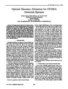
4 BS−Max BS−Max full RS−Max full MRAA MRP MRPA MRFF MRFA Out Opt
3.5
Goodput [b/s/Hz]
3
2.5
2
1.5
1
0.5
5
10
15
20
Rates [Mbps]
Fig. 5.
Cell goodput in [b/s/Hz] for different algorithms, multiple RS case
0.9 0.8 0.7 Outage Probability
20 users, while for the outage, the number of users was fixed to 20. First, it can be observed from Fig. 5 that the throughput achieved by the proposed algorithms is lower than BS–Max full and BS–Max, since these are optimized for the throughput only, while the proposed ones optimize also the outage. Fig. 6 shows that the proposed algorithms achieve a much lower outage than RS–Max full and BS–Max full. Moreover, Fig. 5 shows that there is not a clear difference between the time–division based algorithms, MRP and MRPA, and the frequency–division based ones, MRFF and MRFA. We can observe that, although MRP and MRFF are both fixed schemes, the throughput of MRFF is higher than MRP, which has the worst throughput. This is because the time allocated to the BS–subframe is reduced with the fixed time division, thereby decreasing the overall throughput, whereas with the frequency division, the BS–subframe occupies the half of the frame, thereby supporting a higher number of direct users. However, Fig. 6 shows that concerning outage, frequency division performs better than time division. This is explained in the same way: reducing time affects more the performance than reducing frequencies, since the time allocated to each subframe with MRP is only the half compared to MRFF, while a certain degree of frequency diversity can still be achieved by allocating the third of the subchannels, which contains 4 subchannels or 16 subcarriers. Thus, the frequency division algorithms MRFF and MRFA are better schemes than the time division ones, MRP and MRPA. However, with the per–frame RS activation made by MRAA, the throughput can be really increased. MRAA achieves the best throughput among all the outage–based algorithms, and even higher than Optimized Outage which assumes a full buffer. Concerning outage, MRAA achieves the second best performance among the proposed algorithms for R < 0.3Mbps, and the best one for R ≥ 0.3Mbps. So MRAA achieves a good trade–off between throughput and outage, since it achieves the best throughput and the second outage performance. Finally, the comparison between the proposed algorithms shows that the static time/frequency allocations are quite inefficient, especially for the throughput. This is due to the unused subframes, where no users are attached to the corresponding RS pairs. This result validates the fact that by introducing the RS activation with a little bit higher complexity, the performance can be much improved.
0.6 0.5 BS−Max full RS−Max full MRAA MRP MRPA MRFF MRFA Out Opt
0.4 0.3 0.2 0.1 0
0.05
0.1
0.15 0.2 0.25 Rates [Mbps]
0.3
0.35
0.4
Fig. 6. Outage Probability for proposed and reference algorithms, multiple RS case
which made use of the proposed adaptive RS activation. As an extension of this work, other algorithms are being designed in order to approach even more the performance bounds. ACKNOWLEDGMENT We would like to thank Samsung Electronics for supporting this work. R EFERENCES [1] H. Viswanathan and S. Mukherjee, “Performance of Cellular Networks with Relays and Centralized Scheduling,” IEEE Trans. Wireless Comm., vol. 4, no. 5, pp. 2318–2328, September 2005. [2] H. Hu and H. Liu, “Range Extension without Capacity Penalty in Cellular Networks with Digital Fixed Relays,” in IEEE GLOBECOM, Dallas, Texas, December 2004. [3] J. Z. D. Zheng and J. Sadowsky, “Hierarchical Multiuser Diversity (HMD) Transmission Scheme,” in IEEE GLOBECOM, San Francisco, CA, December 2003. [4] G. Li and H. Liu, “Resource Allocation for OFDMA Relay Networks,” in Thirty-eighth Asilomar Conference on Signals, Systems & Computers, Pacific Grove, CA, November 2004. [5] M. Herdin, “A Chunk Based OFDM Amplify-and-Forward Relaying Scheme for 4G Mobile Radio Systems,” in IEEE ICC, Turkey, June 2006. [6] F.-C. R. et al, “Recommendation on PMP Mode Compatible TDD Frame Structure,” IEEEC802.16MMR-05 027r1, Nov 2005. [7] I.-K. F. et al, “Reverse Link Performance of Relay-based Cellular Systems in Manhattan-like Scenario,” IEEEC802.16MMR-06 004r1, Jan 2006.