a frame-by-frame basis for relay-enhanced cellular networks. To make ...... With AMC, the achievable data rate, which reflects the channel condition, can be used.
Resource Allocation in OFDMA Relay-Enhanced Cellular Networks
Liping Wang
DOCTOR OF PHILOSOPHY
Department of Informatics School of Multidisciplinary Sciences The Graduate University for Advanced Studies (SOKENDAI)
2010
May 2010
c
2010 - Liping Wang
All rights reserved.
Thesis advisor
Author
Yusheng Ji
Liping Wang
Resource Allocation in OFDMA Relay-Enhanced Cellular Networks
Abstract The rapid development of audio and video applications such as Skype and YouTube increases people’s demands for ubiquitous high-data-rate coverage. Orthogonal FrequencyDivision Multiple Access (OFDMA) relay-enhanced cellular network, the integration of multihop relaying with OFDMA infrastructure, has become one of the most promising solutions for next-generation wireless communications. In a relay-enhanced cell, multiple Relay Stations (RSs) are deployed to assist transmissions between a Base Station (BS) and multiple Mobile Stations (MSs). However, the resource allocation becomes more complicated and crucial to gain the potential capacity and coverage improvements of relaying. Although many studies have been done on allocating resource adaptively in the traditional single-hop OFDMA networks, they can’t be applied to OFDMA relay-enhanced networks directly, since with the deployment of relays, resource allocation on different hops should cooperate to avoid data shortage or overflow in relays. In this dissertation, we aim to design efficient and feasible algorithms to allocate OFDMA downlink resources in a frame-by-frame basis for relay-enhanced cellular networks. To make the resource allocation problem tractable, we first consider a single cell without channel reuse, and suppose the basic unit for resource scheduling is a subchannel, each subchannel can be assigned to only one user during a scheduling period, and users’ traffic iii
iv
Abstract
is infinitely backlogged. Under these assumptions, we formulate the optimal instantaneous resource allocation problem with total power constraint to achieve the proportional fairness in the long term. Since the problem is a NP-hard combination optimization problem with non-linear constrains, it’s very difficult to find the optimal solution within a designated time by extensive searching over all possible solutions. We first propose a low-complex resource allocation algorithm under a constant power allocation named ’VF w PF’. A void filling method is employed in ’VF w PF’ to make full use of subchannels. Further more, we use continuous relaxation and a dual decomposition approach to solve the original optimization problem efficiently in its Lagrangian dual domain. A modified iterative water-filling algorithm ’PA w PF’ is proposed to find the optimal path selection, power allocation and subchannel scheduling. Simulation results show the optimal power allocation can not gain much on system throughput, moreover, our optimization algorithms improve the throughput of celledge users and achieve a tradeoff between system throughput maximization and fairness among users. However, if the basic unit for resource scheduling is a slot or users’ traffic is not infinitely backlogged, the resource allocation problem becomes more complicated thus it is difficult to find optimal solutions by using optimization approaches. Therefore, we propose two heuristic resource allocation schemes including a Centralized Scheduling with Void Filling (CS-VF) and a adaptive semi-distributed resource allocation scheme. Based on CS-VF, four representative single-hop scheduling algorithms including RoundRobin (RR), Max Carrier-to-Interference ratio (Max C/I), max-min fairness, and Proportional Fairness (PF), are extended to multihop scenarios to achieve different levels of fair-
Abstract
v
ness. Simulation results indicate that CS-VF is more adaptable to different traffic distributions and dynamic network topologies. On the other hand, the proposed semi-distributed resource allocation scheme consists of a constant power allocation, adaptive subframe partitioning (ASP), and link-based or end-to-end packet scheduling. Simulation results indicate that the ASP algorithm increases system utilization and fairness. Max C/I and PF scheduling algorithms extended using the end-to-end approach obtain higher throughput than those using the link-based approach, but at the expense of more system overhead for information exchange between BS and RSs. The resource allocation scheme using ASP and end-to-end PF scheduling achieves a tradeoff between system throughput maximization and fairness. Finally, we compare four relay-channel partition and reuse schemes in a multi-cell scenario from interference mitigation and throughput improvement points of view. Among these four schemes, 7-part partitioning (PF7) and 4-part partitioning (PF4) schemes mitigate co-channel interferences by relay-channel partitioning, while the other two schemes include partial reuse (PR) and full reuse (FR) schemes improve the throughput by relaychannel partition as well as reuse. Specially, the PR scheme achieves a tradeoff between spectral efficiency and outage. In conclusion, we formulate the optimal resource allocation problem under different assumptions in OFDMA relay-enhanced cellular networks and give both theoretically and practically efficient polynomial-time solutions. From the theoretical point of view, we use optimization approaches including continuous relaxation and dual decomposition to find the jointly optimized power allocation, path selection and subchannel scheduling to achieve proportional fairness. From the implementation point of view, we propose two
vi
Abstract
resource allocation architectures including a centralized allocation and a adaptive semidistributed allocation, with which four representative single-hop scheduling algorithms are extended to achieve different levels of fairness in multihop scenarios. Simulation results show our optimization algorithms achieve a tradeoff between system throughput optimization and fairness among users. Simulation results further suggest that the heuristic algorithm PR+ASP+e2e-PF provides an efficient and feasible solution for multi-cell OFDMA relay-enhanced cellular networks.
Contents Title Page . . . . . . Abstract . . . . . . . Table of Contents . . List of Figures . . . . List of Tables . . . . List of Abbreviations List of Publications . Acknowledgments . .
. . . . . . . .
. . . . . . . .
. . . . . . . .
. . . . . . . .
. . . . . . . .
1 Introduction 1.1 Background . . . . . . . 1.2 Motivation . . . . . . . . 1.3 Related Work . . . . . . 1.4 Contributions . . . . . . 1.5 Dissertation Organization
. . . . . . . .
. . . .
. . . . . . . .
. . . . .
. . . . . . . .
. . . . .
. . . . . . . .
. . . . .
. . . . . . . .
. . . . .
. . . . . . . .
. . . . .
. . . . . . . .
. . . . .
. . . . . . . .
. . . . .
. . . . . . . .
. . . . .
. . . . . . . .
. . . . .
. . . . . . . .
. . . . .
. . . . . . . .
. . . . .
. . . . . . . .
. . . . .
. . . . . . . .
. . . . .
. . . . . . . .
. . . . .
. . . . . . . .
. . . . .
. . . . . . . .
. . . . .
. . . . . . . .
. . . . .
. . . . . . . .
. . . . .
. . . . . . . .
. . . . .
. . . . . . . .
. . . . .
. . . . . . . .
. . . . .
2 OFDMA Relay-enhanced Cellular Networks 2.1 Network Architecture . . . . . . . . . . . . . . . . . . . . . . . . 2.2 Frame Structure . . . . . . . . . . . . . . . . . . . . . . . . . . . 2.3 Frame-by-Frame Resource Allocation . . . . . . . . . . . . . . . 2.3.1 Subchannel-based vs. slot-based . . . . . . . . . . . . . . 2.3.2 Centralized vs. semi-distributed . . . . . . . . . . . . . . 2.3.3 Infinitely backlogged traffic vs. finitely backlogged traffic 2.3.4 Optimization approaches vs. heuristic solutions . . . . . . 2.4 Summary . . . . . . . . . . . . . . . . . . . . . . . . . . . . . . 3 Optimal Resource Allocation with Proportional Fairness 3.1 Introduction . . . . . . . . . . . . . . . . . . . . . . . 3.2 Problem Formulation . . . . . . . . . . . . . . . . . . 3.3 A Low Complexity Resource Allocation Algorithm . . 3.3.1 Constant power allocation . . . . . . . . . . . vii
. . . .
. . . .
. . . .
. . . .
. . . .
. . . .
. . . . . . . .
. . . . .
. . . . . . . .
. . . .
. . . . . . . .
. . . . .
. . . . . . . .
. . . .
. . . . . . . .
. . . . .
. . . . . . . .
. . . .
. . . . . . . .
. . . . .
. . . . . . . .
. . . .
. . . . . . . .
i iii vii x xii xiii xiv 1
. . . . .
2 2 5 8 10 13
. . . . . . . .
15 16 18 18 19 20 21 22 22
. . . .
24 24 26 28 28
viii
Contents
. . . . . . . . . .
. . . . . . . . . .
. . . . . . . . . .
. . . . . . . . . .
. . . . . . . . . .
. . . . . . . . . .
. . . . . . . . . .
. . . . . . . . . .
. . . . . . . . . .
. . . . . . . . . .
. . . . . . . . . .
. . . . . . . . . .
. . . . . . . . . .
. . . . . . . . . .
. . . . . . . . . .
. . . . . . . . . .
29 31 32 32 35 36 38 38 40 42
4 A Novel Centralized Resource Allocation Scheme 4.1 Introduction . . . . . . . . . . . . . . . . . . . 4.2 System Model . . . . . . . . . . . . . . . . . . 4.3 Proposed Centralized Scheduling Scheme . . . 4.3.1 Centralized scheduling with void filling 4.3.2 Four scheduling algorithms . . . . . . . 4.3.3 Calculation of Parameters . . . . . . . 4.4 Problem Formulation . . . . . . . . . . . . . . 4.4.1 Simulation setup . . . . . . . . . . . . 4.4.2 Simulation results . . . . . . . . . . . 4.5 Summary . . . . . . . . . . . . . . . . . . . .
. . . . . . . . . .
. . . . . . . . . .
. . . . . . . . . .
. . . . . . . . . .
. . . . . . . . . .
. . . . . . . . . .
. . . . . . . . . .
. . . . . . . . . .
. . . . . . . . . .
. . . . . . . . . .
. . . . . . . . . .
. . . . . . . . . .
. . . . . . . . . .
. . . . . . . . . .
. . . . . . . . . .
44 44 45 46 46 48 50 52 52 52 58
. . . . . . . . . . . . .
60 60 61 61 62 66 66 68 70 74 75 78 79 84
3.4
3.5
3.6
3.3.2 Void filling . . . . . . . . . . . . . 3.3.3 Summary of the proposed algorithm Joint Optimization Algorithm . . . . . . . . 3.4.1 Dual decomposition . . . . . . . . 3.4.2 A modified iterative water-filling . . 3.4.3 Summary of the proposed algorithm Performance Evaluation . . . . . . . . . . . 3.5.1 Simulation setups . . . . . . . . . . 3.5.2 Simulation results . . . . . . . . . Summary . . . . . . . . . . . . . . . . . .
. . . . . . . . . .
5 A Semi-distributed Resource Allocation Scheme 5.1 Introduction . . . . . . . . . . . . . . . . . . . . . . . . . . . . . . . . . 5.2 System Model and Problem Formulation . . . . . . . . . . . . . . . . . . 5.2.1 System model . . . . . . . . . . . . . . . . . . . . . . . . . . . . 5.2.2 Problem Formulation . . . . . . . . . . . . . . . . . . . . . . . . 5.3 Proposed Resource Allocation Scheme . . . . . . . . . . . . . . . . . . . 5.3.1 Semi-distributed Architecture . . . . . . . . . . . . . . . . . . . 5.3.2 Adaptive Subframe Partitioning Algorithm . . . . . . . . . . . . 5.3.3 Packet Scheduling Algorithms . . . . . . . . . . . . . . . . . . . 5.3.4 Discussion . . . . . . . . . . . . . . . . . . . . . . . . . . . . . 5.4 Performance Evaluation . . . . . . . . . . . . . . . . . . . . . . . . . . . 5.4.1 Performance of the adaptive subframe partitioning . . . . . . . . 5.4.2 Performance of link-based and end-to-end scheduling algorithms . 5.5 Summary . . . . . . . . . . . . . . . . . . . . . . . . . . . . . . . . . .
6 Relay-Channel Partition and Reuse 85 6.1 Introduction . . . . . . . . . . . . . . . . . . . . . . . . . . . . . . . . . . 85 6.2 Multicell OFDMA relay-enhanced networks . . . . . . . . . . . . . . . . . 86 6.3 Channel Partition and Reuse Schemes . . . . . . . . . . . . . . . . . . . . 87
Contents
6.4
6.5
6.6
ix
6.3.1 PF7 Scheme . . . . . . . . . . . . 6.3.2 PF4 Scheme . . . . . . . . . . . . 6.3.3 PR Scheme . . . . . . . . . . . . . 6.3.4 FR Scheme . . . . . . . . . . . . . Performance Analysis . . . . . . . . . . . . 6.4.1 SINR Calculation . . . . . . . . . . 6.4.2 Co-channel Interference Analyses . 6.4.3 Resource Efficiency . . . . . . . . Performance Evaluations . . . . . . . . . . 6.5.1 Simulation method and parameters . 6.5.2 Simulation results . . . . . . . . . Summary . . . . . . . . . . . . . . . . . .
. . . . . . . . . . . .
. . . . . . . . . . . .
. . . . . . . . . . . .
. . . . . . . . . . . .
. . . . . . . . . . . .
. . . . . . . . . . . .
. . . . . . . . . . . .
. . . . . . . . . . . .
. . . . . . . . . . . .
. . . . . . . . . . . .
. . . . . . . . . . . .
. . . . . . . . . . . .
. . . . . . . . . . . .
. . . . . . . . . . . .
. . . . . . . . . . . .
. . . . . . . . . . . .
. . . . . . . . . . . .
89 90 90 91 91 92 92 97 97 97 99 103
7 Conclusion and Future work 105 7.1 Conclusion and Discussion . . . . . . . . . . . . . . . . . . . . . . . . . . 105 7.2 Future work . . . . . . . . . . . . . . . . . . . . . . . . . . . . . . . . . . 108 Bibliography
111
List of Figures 1.1 1.2
Typical Usage models for IEEE 802.16j systems [14]. . . . . . . . . . . . . A three-node DF relaying system. . . . . . . . . . . . . . . . . . . . . . .
4 7
2.1 2.2
The architecture of OFDMA relay-enhanced cellular networks. . . . . . . . Four representative cooperative relaying schemes that work in the twosubframe relaying pattern (a)cooperative transmit diversity-1 (b)cooperative transmit diversity-2 (c)cooperative receive diversity (d)cooperative selection diversity . . . . . . . . . . . . . . . . . . . . . . . . . . . . . . . . . A MAC frame structure for relay-enhanced IEEE 802.16 networks. . . . . . Dowlink data subframe for OFDMA relay-enhanced networks . . . . . . . Resource allocation architecture for OFDMA relay-enhanced cellular networks. . . . . . . . . . . . . . . . . . . . . . . . . . . . . . . . . . . . . .
17
2.3 2.4 2.5 3.1 3.2 3.3 3.4 4.1
4.2 4.3 4.4 4.5
An example of (a) direct transmission and decode-and-forward relaying when (b) u = 1/3, (c) u = 1/2, (d) u = 1/2 with void filling . . . . . . . . System throughput under various total power constraints. . . . . . . . . . Fairness index under various total power constraints. . . . . . . . . . . . Average throughput for cell-edge users when different number of RSs are located in the cell. . . . . . . . . . . . . . . . . . . . . . . . . . . . . . . An example of CS-VF scheme with E-RR: (a) An OFDMA relay-enhanced cellular network and the link sets, (b) A example scheduluing results for the system shown in (a). . . . . . . . . . . . . . . . . . . . . . . . . . . . . System throughput of different scheduling schemes under various S 1 /S values . . . . . . . . . . . . . . . . . . . . . . . . . . . . . . . . . . . . Throughput fairness index of different scheduling schemes under various S 1 /S values . . . . . . . . . . . . . . . . . . . . . . . . . . . . . . . . . End-to-end delay for single-hop users and for two-hop users of different scheduling schemes with E-RR under various S 1 /S values . . . . . . . . System throughput of different scheduling algorithms under various system loads . . . . . . . . . . . . . . . . . . . . . . . . . . . . . . . . . . . . . x
17 19 20 21
. 30 . 41 . 42 . 43
. 47 . 54 . 55 . 56 . 57
List of Figures
xi
4.6
Throughput fairness index of different scheduling algorithms under various system loads . . . . . . . . . . . . . . . . . . . . . . . . . . . . . . . . . . 58
5.1 5.2 5.3
Downlink data subframe structure for semi-distributed resource allocation. Information exchange in adaptive subframe partitioning. . . . . . . . . . System capacity under equal slot allocation when there are various number of RSs equally spaced on a circle centered by the BS. . . . . . . . . . . . Spectrum efficiency of a user located on a cell radius where one of the RSs is located. . . . . . . . . . . . . . . . . . . . . . . . . . . . . . . . . . . System throughput of e2e-PF with or without ASP in various scenarios. . Throughput fairness index of e2e-PF with or without ASP in various scenarios. . . . . . . . . . . . . . . . . . . . . . . . . . . . . . . . . . . . . System throughput of different scheduling algorithms under various system loads. . . . . . . . . . . . . . . . . . . . . . . . . . . . . . . . . . . . . Throughput fairness index of different scheduling algorithms under various system loads. . . . . . . . . . . . . . . . . . . . . . . . . . . . . . . . . User’s throughput at different distance from the BS when there are 30 users uniformly distributed on a cell reditus where one of a RS is located. . . .
5.4 5.5 5.6 5.7 5.8 5.9 6.1 6.2 6.3 6.4
6.5 6.6 6.7 6.8 6.9
. 63 . 70 . 77 . 78 . 79 . 80 . 81 . 82 . 83
Layout of 19 hexagonal relay-enhanced cells . . . . . . . . . . . . . . . . The architecture of an OFDMA relay-enhanced cell. . . . . . . . . . . . . Transmission range of RSs in each cell when distance-based path selection algorithm is used . . . . . . . . . . . . . . . . . . . . . . . . . . . . . . . Illustrations of four relay-channel partition and relay schemes when distancebased path selection algorithm is used (Each color block denotes a set of subchannels being assigned to that region, and the LOS links between the BS and each RS are not marked) . . . . . . . . . . . . . . . . . . . . . . . Average RSS per-subchannel at different distances from BS . . . . . . . . . Average SINR at different distances from BS . . . . . . . . . . . . . . . . Empirical CDF of user’s SINR . . . . . . . . . . . . . . . . . . . . . . . . Average spectral efficiency of different resource allocation schemes . . . . Outage ratio of different resource allocation schemes . . . . . . . . . . . .
87 87 88
89 100 100 101 102 103
List of Tables 3.1
Simulation Parameters for Optimal Resource Allocation with PF . . . . . . 38
4.1
Simulation Parameters for a Centralized Resource Allocation Scheme . . . 53
5.1
Simulation Parameters for a Semi-distributed Resource Allocation Scheme . 76
6.1
Simulation Parameters for Relay-Channel Partition and Reuse Schemes . . 98
xii
List of Abbreviations 3GPP AWGN AMC ASP BS C/I CNR CDF CS-VF DF DL DL-MAP e2e-PF FIFO HARQ IEEE LOS LTE MAC MS NLOS OFDMA PF PHY RR R-RTG RS RSS SINR SNR UL UL-MAP VoIP
Third Generation Partnership Project Additive white Gaussian noise Adaptive Modulation and Coding Adaptive Subframe Partitioning Base Station Carrier-to-Interference ratio Carrier-to-Noise power Ratio Cumulative Density Function Centralized Scheduling with Void Filling Decode-and-Forward Downlink Downlink Mapping end-to-end Proportional Fairness First-In-First-Out Hybrid Automatic Repeat reQuest Institute of Electrical and Electronics Engineers Line of Sight Long Term Evolution Media Access Control Mobile Station Non-Line of Sight Orthogonal Frequency Division Multiple Access Proportional Fairness Physical Round-Robin Relay Receive/Transmit transition Gap Relay Station Received Signal Strength Signal-to-Interference-plus-Noise Ratio Signal-to-Noise Ratio Uplink Uplink Mapping Voice over Internet Protocol
xiii
List of Publications Transactions and Journals 1. L. WANG, Y. JI, and F. LIU, ”Adaptive Subframe Partitioning and Efficient Packet Scheduling in OFDMA Cellular Systems with Fixed Decode-and-Forward Relays,” IEICE Transactions on Communications, Vol. E92-B, No.3, pp.755-765, 2009.
International Conference Proceedings 1. L. WANG, Y. JI, and F. LIU, ”Joint Optimization for Proportional Fairness in OFDMA Relay-Enhanced Cellular Networks,” in Proc. of IEEE Wireless Communications and Networking Conference 2010 (WCNC’10), April 2010, Sydney, Australia. 2. L. WANG, Y. JI, and F. LIU, ”Resource Allocation for OFDMA Relay-Enhanced System with Cooperative Selection Diversity,” in Proc. of IEEE Wireless Communications and Networking Conference (WCNC’09), April 2009, Budapest, Hungary. 3. L. WANG, Y. JI, and F. LIU, ”A Semi-Distributed Resource Allocation Scheme for OFDMA Relay-Enhanced Downlink Systems,” in Proc. of the 4th IEEE Broadband Wireless Access workshop (BWA’08), December 2008, New Orleans, USA. 4. L. WANG, Y. JI, and F. LIU, ”A Novel Centralized Resource Scheduling Scheme in OFDMA-based Two-hop Relay-Enhanced Cellular Systems,” in Proc. of the 4th IEEE International Conference on Wireless and Mobile Computing, Networking and Communications (WiMob’08), October 2008, Avignon, France. 5. L. WANG, Y. JI, F. LIU, and J. LI, ”Performance Improvement through Relay Channel Partitioning and Reuse in OFDMA Multihop Cellular Networks,” in Proc. of International Wireless Communications and Mobile Computing conference (IWCMC08), August 2008, Crete Island, Greece. xiv
List of Publications
xv
6. L. SHAN, L. WANG, F. LIU, and Y. JI, ”Predictive Group Handover Scheme with Channel Borrowing for Mobile Relay Systems,” in Proc. of International Wireless Communications and Mobile Computing conference (IWCMC’08), August 2008, Crete Island, Greece. 7. L. WANG, Y. JI, and F. LIU, ”Performance Analysis of Fast Handover Schemes in IEEE 802.16e Broadband Wireless Networks,” in Proc. of 24th Asia-Pacific Advanced Network Research Workshop (APAN’07), August 2007, Xi’an, P. R. China.
Presentations and Technical Reports 1. L. WANG, Y. JI, and F. LIU, ”Performance Evaluation of Resource Allocation Schemes in OFDMA Two-Hop Relay-Enhanced Cellular Networks,” in IEICE 2008 General Conference, March 2008, Kitakyushu, Japan. 2. L. WANG, Y. JI, and F. LIU, ”A Study on the Performance of Fast Handover Schemes in IEEE 802.16e Broadband Wireless Networks,” in IEICE 2007 Society Conference (English Session Award), September 2007, Tottori, Japan. 3. N. RUANGCHAIJATUPON, L. WANG, Y. JI, and F. LIU, ”A Study on the Performance of Scheduling Schemes for Broadband Wireless Access Networks,” in IEICE 2006 Society Conference, September 2006, Kanazawa, Japan.
Acknowledgments First I want to express my sincere gratitude to my advisor Assoc. Prof. Yusheng Ji for her understanding, encouraging and enlightening guidance. She is a very respectable person for her personality, knowledge and creativity. I learned a lot from her comments and suggestions, and from many fruitful discussions we had over these years. Without her continuous support and help, this work could not have been possible. I would also like to give my hearty thanks to Prof. Shigeki Yamada, Prof. Shigeo Urushidani, Assoc. Prof. Kensuke Fukuda, Assoc. Prof. Shunji Abe, and Prof. Noboru Sonehara in National Institute of Informatics (NII) for their constructive suggestions and valuable advices. Special thanks go to Prof. Fuqiang Liu from Tongji university for introducing me to the world of scientific research and also for his continuous help. Moreover, I want to say thanks to my colleagues and friends for the wonderful days we share, and also for helping me throughout these years. I am also thankful to Mizuki Matsuoka san, Akiko Ito san, Miyuki Kobayashi san, and to all the administrative staff in NII, for their assistances in traveling, scholarship and other issues. Last but not least, I give my deepest gratitude to my father Delin, my mother Qiuling and my boyfriend Huimin for their continuous understanding, support and patience. This work had been financially supported by the MoU scholarship from NII. There are too many names to be mentioned here, thank you all!
1
Chapter 1 Introduction This chapter provides a brief background and highlights the importance of resource allocation in Orthogonal Frequency Division Multiple Access (OFDMA) relay-enhanced cellular networks. We also give an overview of related work and author’s contributions.
1.1 Background The Orthogonal Frequency Division Multiple Access (OFDMA) is a promising multiple access technique for next-generation wireless communications because of its high spectral efficiency and inherent robustness against frequency-selective fading [5] [11] [13] [54]. In the emerging OFDMA-based standards such as 3rd Generation Partnership Project (3GPP) Long Term Evolution (LTE) [1] [41] and IEEE 802.16j [2][23], the multihop relay concept has been introduced to provide ubiquitous high-data-rate coverage. IEEE 802.16j was approved and published by IEEE in 2009 as an amendment to IEEE Std 802.16-2009 2
Chapter 1: Introduction
3
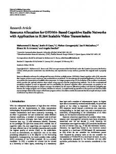
[22]. The purpose of IEEE 802.16j is not to standardize a new cellular network that includes multihop capability, but instead to expend previous single-hop 802.16 standards to include multihop capability [37]. The two standards supporting multihop relaying, LTE-Advanced and IEEE 802.16j, are amendments of LTE and IEEE 802.16-2009, respectively. Therefore, they must have backward compatibility. Namely, the new amendment standards not only must be fully compatible with devices for their baseline standards, but also must satisfy the new functionality of multihop relaying. The functionality of relaying can be implemented by both hardware and software changes on the baseline devices. The choice should be made according to the cost of the two ways. For example, if the baseline devices have been deployed widely, it’s better to add new functionality by software updating since it’s very expensive to re-deploy the new hardware. Fortunately, the two baseline standards for multhop relaying are still in the standardization stage, thus how to implement multihop relaying is still an open problem. Multihhop relays not only can be used in fixed infrastructures, but also can provide inbuilding coverage, coverage on mobile vehicle, and temporary coverage for emergency and disaster recover. Four typical usage models [14] for multihop relays are shown in Figure. 1.1. In the fixed infrastructure usage model of multihop relays, relay stations (RSs) are deployed in the cellular infrastructure to improve system capacity and coverage by dividing one long path into several shorter links and by offering alternative paths to users located in shadow areas. The deployment of multihop relay can decrease the deployment costs because the conventional cellular system requires a very higher density of Base Station (BS) to provide sufficient coverage, and the deployment cost of a BS is higher than that of a RS since a
4
Chapter 1: Introduction
(2) In-building coverage (1) Fixed infrastructure
(3) Coverage on mobile vehicle
(4) Temporary coverage
Figure 1.1: Typical Usage models for IEEE 802.16j systems [14].
RS does not need a wired backbone access. Moreover, the flexibility in relay positioning allows a faster network construction. By introducing multihop relaying to OFDMA cellular networks, larger capacity and coverage can be expected; however, there are still lots of challenges. The new standard 802.16j must not only be compatible with old devices such as 802.16e devices, but also satisfy cooperative relaying functionality. From the physical layer perspective, backward compatibility requires every RS should be able to support all the modulation and coding schemes in the old standard. Moreover, since every Mobile Station (MS) may receive from the BS and a RS in the same frame, this raises more strict requirements regarding channel estimation, synchronization and frequency offset. From the Media Access Control (MAC) layer perspective, an entirely new set of mes-
Chapter 1: Introduction
5
sages specific to relaying must be created in 802.16j without overlapping with the existing set of MAC messages in IEEE 802.16-2009 [22]. The new MAC not only is responsible for ensuring a required Quality of Service (QoS) over multihops and allowing handovers among BS and RSs, but also should maintain Hybrid automatic repeat request (HARQ) over multiple hops. Technical issues such as frequency reuse, relay placement, resource allocation and scheduling are very difficult, yet extremely important, problems that IEEE 802.16j has left to manufacturers and providers to solve [37].
1.2 Motivation Nowadays, due to the rapid developments of audio and video applications such as Skype and YouTube, people’s demands for high-data-rate wireless access are increasing. To provide ubiquitous high-data-rate coverage, advanced signal processing techniques such as OFDMA are developed. However, due to the path loss of radio propagation, those advanced techniques can not improve data rates for cell-edge users, namely users far from the BS. The most widely used strategy to address this problem is to shrink the size of cells to increase the density of BSs. However, the benefit of this strategy is limited by the exceeding cost of deploying a BS since the service provider must pay for not only the antenna space but also the wired backhaul connection. Multihop relaying is considered to be a more attractive solution since relay stations do not need wired backhaul. One the other hand, the flexibility in relay positioning allows a faster network construction. Therefore, OFDMA relay-enhanced cellular network is a promising solution for the next-generation communications.
6
Chapter 1: Introduction
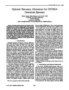
To implement OFDMA relay-enhanced cellular network, resource allocation is one of the issues remained for our researchers, manufacturers and service providers to investigate. We focus on the resource allocation problem in OFDMA relay-enhanced cellular networks. To gain the potential capacity and coverage improvements of multihop relaying, the resource allocation problem becomes more complicated and crucial. Although many studies have been done on adaptive resource allocation in single-hop OFDMA cellular systems [30] [40] [58], they can’t be used directly in the multihop system, since in the multihop system, resource allocation on different hops should be cooperated to avoid data shortage or overflow in relay nodes. The RS we considered is a regenerative relay, which has a layer-2 protocol structure and works in the decode-and-forward (DF) mode. DF relays first decode and verify the correctness of the received data, and then forward the re-encoded data to destinations [51]. Compared with amplify-and-forward relaying [7], DF has significant advantages on noise propagation avoidance and link adaptation with different modulation/coding schemes on different hops [32]. Since we consider providing high data rate coverage to residential or business customers, RSs can be fixed on tops of buildings to provide high computation capability for decoding and re-encoding. Figure 1.2 gives a simple three-node DF relaying system. With DF and Adaptive Modulation and Coding (AMC), achievable data rates of different links can adaptive to corresponding link qualities. In the example, we suppose there’s a single channel and the achievable data rates of user’s direct link, first-hop link and second-hop link are 2 bits-persecond (bps), 8 bps and 4 bps respectively. Moreover, the arrival rate for user’s downlink (DL) data is assumed to be 2.5 bps.
Chapter 1: Introduction
7
2.5 bps BS 8 bps RS
2 bps
4 bps MS
Figure 1.2: A three-node DF relaying system. With single-hop transmission, obviously, user’s throughput is 2 bps and the queue length in BS increases with a speed of 0.5 bps. However, if the two-hop DF relaying is considered, user’s throughput not only relies on achievable data rates on two links, but also depends on the proportion of slots allocated to the BS-RS and the RS-MS links. The maximum throughout can be achieved if we consider the cooperated resource allocation on the two hops. That is at least 2.5/8 = 31.25% of the channel duration is allocated to the BS-RS link while at least 2.5/4 = 62.5% of the channel duration is assigned to the RS-MS link. Since 31.26% + 62.51% < 100%, the user can achieve a throughput equal to the arrival rate of its downlink data, i.e. 2.5 bps, and the queue length in both BS and RS is stable. In Figure 1.2, if we don’t care about cooperation, for instance, we just allocate 3/4 of the total resources to the BS-RS link and the remaining 1/4 to the RS-SS link, user’s throughput is reduced to 1 bps and the queue length in the RS increases with a speed of 1.5 bps, hence, data overflow will happen after a certain time duration. If the arrival data rate for this user increases to 3 bps, it’s very hard to find a resource allocation scheme to maximize user’s throughput intuitively.
8
Chapter 1: Introduction
Therefore, resource allocation is more complex and challenging in OFDMA relayenhanced cellular networks than in the conventional single-hop OFDMA system. When the numbers of channels and users are large, the resource allocation becomes more complicated and crucial to gain the potential capacity and coverage improvements.
1.3 Related Work Resource allocation in OFDMA relay-enhanced cellular networks becomes a flourishing topic recently [35] [52] [53]. However, there still exist some challenges. The first one is how to allocate resources cooperatively to reduce the wastes of radio resources due to the unbalance between capacities on two links of a user who receive data via a RS. In [27], the authors use the Lagrange dual-decomposition method to show that with fixed subchannel allocation, a modified water-filling algorithm is the optimal power-allocation solution. However, if AMC is used, power allocation does not contribute much to system performance improvement [17] [40]. In [18], a heuristic centralized subcarrier and power allocation algorithm with a constraint on overall transmission power is proposed. However, their formulations are based on a ”half-and-half” frame structure, in which the first half of a time frame is allocated to transmissions from BS and the second half is dedicated to transmissions from RSs. If the RSs’ positions are fixed, this ”half-and-half” frame structure can not adapt to various traffic demands. In [32], [33] and [45], the optimal RSs locations are studied when the network topology, traffic distribution and transmission power are determinate. However, in OFDMA cellular networks with fixed RSs, it is costly to re-install RSs at different locations when the traffic distribution changes. The most efficient way is using dynamic resource allocation that
Chapter 1: Introduction
9
assigns different amounts of resources to RSs according to various traffic demands and topologies. Furthermore, some resource allocation algorithms are based on unrealistic assumptions, for instance user traffic is infinitely backlogged and all RSs can receive and transmit the same data packets during one frame, for example the three resource scheduling algorithms proposed in [19]. Although the second assumption simplifies the resource scheduling problem, it is not applicable to practical systems since it requires every RS should have a very high processing speed to decode and re-encode in a Relay Receive/Transmit transition Gap (R-RTG). Moveover, whether resource allocation in relay-enhanced networks should be performed in a centralized manner or semi-distributed manner? In [9], a centralized throughput enhancement scheduling scheme is proposed. In [7], a semi-distributed relaying algorithm is proposed for amplify-and-forward relaying networks. Centralized scheduling can reduce the complexity of RSs, but has a the high system overhead for control message exchange, since the BS requires full knowledge of the Channel State Information (CSI) of each link as well as the queue length in every RS, while every RS needs to be informed about the BS’s allocation. To the best of the author’s knowledge, there’s no existing work refer to semi-distributed resource allocation for OFDMA relay-enhanced cellular networks. Although there is a rich literature that considers the resource allocation for relay-enhanced cellular networks, most of them aim to maximize the sum-rate, such as [18], [25], [27], [34], and [59]. However, under the sum-rate maximization objective, users with bad channel conditions are starved since all resources are assigned to users with good channel conditions. Considering fairness among users, an uplink subchanel allocation problem is studied
10
Chapter 1: Introduction
with restricted number of subchannels for every RS in [31]. A heuristic resource allocation algorithm that limit the maximum number of subchannels allocated to every user is proposed in [4]. Further more, an sum-rate optimization problem with minimal rate requirements from users is solved by a subgradient method in [43]. When every user has the same rate requirement, fairness can be guaranteed to a certain extent. However, admission control policies are needed to make the optimal solutions feasible, i.e. all rate requirements should be met for admitted users. In [56] and [28], optimal resource allocations for max-min fairness are proposed. In max-min fairness, the sum-up rate is limited by rates of users in bad channel conditions. However, due to the undesigned radio propagation effects in wireless channel such as path loss, shadowing and fading, there’s a high probability that channel conditions for some users are very bad. Therefore, the Proportional Fairness (PF) seems more attractive than the max-min fairness in wireless networks. PF maximizes the summation of logarithmic function of users’ throughputs and has been proven to gain a tradeoff between system throughput maximization and fairness [3]. In [55], the conventional PF algorithm is enhanced to schedule subchannels dynamically under a constant power allocation.
1.4 Contributions In this dissertation, we aim to design efficient and feasible algorithms for allocating OFDMA downlink resources for relay-enhanced cellular networks in a frame-by-frame basis. The resource allocation in our system model can be formulated into optimization problems with different objectives and constraints. The objective is to optimize system performance such as sum-rate optimization, max-min fairness, proportional fairness and so
Chapter 1: Introduction
11
on. Different constraints are based on different assumptions. However, most of formulated problems are NP-hard and can not solved within a designated time by extensive searching. To make resource allocation problem tractable, in chapter 3, we suppose the basic unit for scheduling is a subchannel, each subchannel can be assigned to only one user during the scheduling period, and users’ traffic is infinitely backlogged. We first formulate the optimal instantaneous resource allocation problem with the total power constraint in OFDMA relay-enhanced cellular networks to achieve the proportional fairness in the long term. Since the problem is a non-linear constrained optimization problem, we first propose a low-complex resource allocation algorithm for a constant power allocation named ’VF w PF’. A void filling method is employed in ’VF w PF’ to make full use of the resources. Further more, we use continuous relaxation and a dual decomposition approach to solve the original optimization problem efficiently in its Lagrangian dual domain. A modified iterative water-filling algorithm ’PA w PF’ is proposed to find the optimal solutions. Simulation results show that our optimization algorithms improve the throughput of cell-edge users, and achieve a tradeoff between system throughput maximization and fairness among users. In chapter 4 and 5, we consider that the basic unit for scheduling is a slot and users’ traffic is not infinitely backlogged. Two heuristic resource allocation schemes are proposed. The first one named Centralized Scheduling with Void Filling (CS-VF) works in the centralized manner. In CS-VF, the remaining slots in the second subframe are filled with packets destined to users who receive data directly from the base station (BS). Moreover, based on our CS-VF scheduling scheme, four representative single-hop scheduling algorithms including round-robin, max C/I, max-min fairness, and proportional fairness, are
12
Chapter 1: Introduction
extended to multihop scenarios to achieve diffident levels of fairness. Simulation results indicate that when compared with the existing centralized scheduling scheme, which does not consider void filling, our proposed CS-VF scheme is more adaptable to different traffic distributions caused by dynamic network topology and user’s mobility. The second heuristic solution works in the semi-distributed manner. We consider there is time division between transmissions from RSs, and partition the second subframe in the downlink data subframe into multiple RS-subframes, each of which is dedicate to transmissions from a RS. Since fixed partition can not adapt to various traffic demands, we propose an Adaptive Subframe Partitioning (ASP) algorithm to adjust the length of every subframe dynamically, and suggest two ways to extend single-hop scheduling algorithms into multihop scenarios: link-based and end-to-end approaches. Simulation results indicate that the ASP algorithm increases system utilization and fairness. The max C/I and PF scheduling algorithms extended using the end-to-end approach obtain higher throughput than those using the link-based approach, but at the expense of more overhead for information exchange between the BS and RSs. The resource allocation scheme using ASP and end-to-end PF scheduling achieves a tradeoff between system throughput maximization and fairness. In chapter 3, 4 and 5, we study resource allocation in a single OFDMA relay-enhanced cell without channel reuse. That is a slot or a subchannel can not be reused by users to avoid intra-cell interference. In chapter 6, four channel partition and reuse schemes are compared in a multi-cell scenario from interference mitigation and throughput improvement points of view. The four channel partition and reuse schemes are are 7-part partitioning (PF7), 4-part partitioning (PF4), partial reuse (PR), and full reuse (FR) schemes. The co-channel inter-
Chapter 1: Introduction
13
ferences of these four schemes in a multi-cell scenario are full-queue analyzed. By using a proposed Monte-Carlo simulation algorithm, the empirical Cumulative Density Function (CDF) curves of user’s Signal-to-Interference-plus-Noise Ratio (SINR) in the worst case are gained in different scenarios. Numerical results show that multihop transmissions are greatly advantageous for improving throughput and reducing outage when compared with single-hop transmissions, and can especially improve the performance of cell-edge users. Among these four schemes, PF7 and PF4 mitigate co-channel interferences by relaychannel partitioning, while the other two schemes PR and FR improve the throughput by relay-channel partitioning as well as reuse. In a word, we study the resource allocation problem for OFDMA relay-enhanced cellular networks in this dissertation not only from the theoretical point of view but also from the implementation point of view. Our optimization algorithms gained by optimization approaches can be used to achieve a tradeoff between system throughput optimization and fairness among users. Simulation results further suggest that the heuristic algorithm PR+ASP+e2e-PF provides an efficient and feasible solution for multi-cell OFDMA relayenhanced cellular networks.
1.5 Dissertation Organization The remainder of this dissertation is structured as follows: Chapter 2 describes the system model of OFDMA relay-enhanced cellular networks includes network architecture and frame structure. It also highlights resource allocation problem under the system model. Chapter 3 formulates the resource allocation problem under the assumptions that the
14
Chapter 1: Introduction
basic unit for scheduling is a subchannel, each subchannel can be assigned to only one user during the scheduling period, and users’ traffic is infinitely backlogged. Optimization approaches are used to achieve optimal resource allocation for proportional fairness among users. The work in this chapter is mainly based on [48] and [46]. Chapter 4 proposes a heuristic resource allocation scheme named Centralized Scheduling with Void Filling (CS-VF). Based on CS-VF, four representative single-hop packet scheduling algorithms: round-robin, max C/I, max-min fairness, and proportional fairness, are extended to multihop OFDMA relay-enhanced networks. The work in this chapter is mainly based on [47]. Chapter 5 proposes a semi-distributed resource allocation scheme to achieve a nearoptimal solution. The proposed scheme consists of a constant power allocation, adaptive subframe partitioning (ASP), and link-based or end-to-end packet scheduling. The work in this chapter is mainly based on [49] and [50]. Chapter 6 compares four channel partition and reuse schemes a multi-cell OFDMA relay-enhanced network from the viewpoints of interference mitigation and throughput improvement. The work in this chapter is mainly based on [42]. Chapter 7 summarized the dissertation and proposes several open topics for future work.
Chapter 2
OFDMA Relay-enhanced Cellular Networks
This chapter describes the system model of OFDMA relay-enhanced cellular networks includes network architecture and frame structure. Under our system model, the basic unit for resource scheduling can be a subchannel or a slot; the resource allocation architecture can work in centralized manner or semi-distributed manner; user traffic pattern can be infinitely backlogged or finitely backlogged. Resource allocation problems under different assumptions have different forms. They can be solved by optimization approaches or heuristic methods. 15
16
Chapter 2: OFDMA Relay-enhanced Cellular Networks
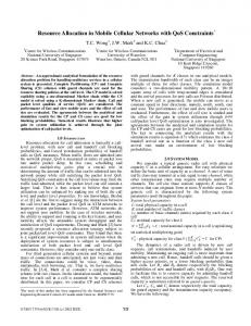
2.1 Network Architecture We consider an OFDMA relay-enhanced cellular network with a Base Station (BS), multiple Relay Stations (RSs), and multiple Mobile Stations (MSs) or users shown in Figure 2.1. Let k ∈ {0, 1, ..., K} denote the index of the BS or a RS, and k = 0 for the BS. The notation k also represents one of the total (K + 1) downlink paths for every user, k = 0 for the direct transmission path whereas k ∈ {1, ..., K} for the relaying path through the kth RS. m ∈ {1, ..., M} is the index of a user. All nodes including the BS, RSs and MSs work in the half-duplex mode thus they can not transmit and receive simultaneously. We do not consider full-duplex radios since they are hard to implement due to the dynamic range of incoming and outgoing signals and the bulk of ferroelectric components like circulators [15]. In the downlink direction, users can receive data directly from the BS or via a RS. We call a user communicating directly with a BS a single-hop user, and a user that alternatively receives data via a RS a two-hop user. Two-hop relaying has been proven to give the highest system throughput, and when the number of hops is larger than three, the system overhead for exchanging control messages uses a great amount of resources [10] [21]. Cooperative selection diversity, which dynamically selects the best transmission scheme between direct transmission and decode-and-forward relaying, is used in the network to achieve the multiuser diversity. Among four representative cooperative relaying schemes shown in Figure 2.2, cooperative selection diversity has been proven to be the most promising one in terms of throughput and implementation complexity since no signal combing is needed in Mobile Stations (MSs) [8]. With cooperative selection diversity shown in Figure 2.2(d), if direct transmission is
Chapter 2: OFDMA Relay-enhanced Cellular Networks
17
RS
Direct transmission
DF relaying
MS BS MS
RS
Figure 2.1: The architecture of OFDMA relay-enhanced cellular networks.
used between a source and a destination, the source send messages directly to the destination during the whole frame, whereas in the case of decode-and-forward relaying, the source transmits to the relay node in the first subframe, after decoding the source messages successfully, the relay node encodes and forwards the messages to the destination in the second subframe. In the downlink of an OFDMA relay-enhanced cellular network, the BS is the source, and users are destinations.
(a)
(b)
(c) Source
or
Relay
Destination
TX in the 1st subframe TX in the 2nd subframe
(d)
Figure 2.2: Four representative cooperative relaying schemes that work in the twosubframe relaying pattern (a)cooperative transmit diversity-1 (b)cooperative transmit diversity-2 (c)cooperative receive diversity (d)cooperative selection diversity
18
Chapter 2: OFDMA Relay-enhanced Cellular Networks
2.2 Frame Structure In frame-based networks, the timeline is divided into consecutive frames, each of which further consists of a downlink (DL) subframe and an uplink (UL) subframe. Figure 2.3 illustrates a multihop MAC frame structure which is proposed in [16] and [23] for relayenhanced IEEE 802.16 networks. MS can compete for transmission opportunities in the uplink subframe. The standards such as 802.16j define the mechanism on how to compete and how to avoid collision in the uplink. After a MS gets a transmission opportunity successfully, it can send the QoS requirements gathered from applications to the BS, and then the BS can allocate resources according to users’ requirements. A DL subframe is further divided into two subframes since the cooperative selection diversity works in the half-duplex relaying pattern. In the downlink direction, BS first broadcasts a control message, which contains a DL-MAP and a UL-MAP messages. With these mapping messages, single-hop users and RSs are notified of the corresponding resources assignments. After receiving messages successfully during the DL subframe 1, each RS converts from receiving mode to transmitting mode in a time gap, and then broadcasts its control message at the beginning of the DL subframe 2, which also includes a mapping message, with which every two-hop user gets the resource allocation information.
2.3 Frame-by-Frame Resource Allocation Resources in wireless communication systems usually refer to time, spectral and power. Suppose resources are allocated on a frame-by-frame basis according to Channel State In-
Chapter 2: OFDMA Relay-enhanced Cellular Networks
Frame n-1
Frame n
DL Subframe
19
Frame n+1
Time
UL Subframe
BS RS Broadcast control messages DL Subframe 1
Contention window
DL Subframe 2
UL Subframe 1
Guard time gap UL Subframe 2
Figure 2.3: A MAC frame structure for relay-enhanced IEEE 802.16 networks.
formation (CSI) estimated from previous feedback. Moreover, channel coherence time is considered to be much longer than the frame length; hence, channel states are invariant during each scheduling epoch. Under the network architecture and the frame structure introduced in section 2.1 and 2.2 respectively, we divide the resource allocation in an OFDMA relay-enhance cellular network into three tasks: power allocation among all subchannals, path selection for every users, and data frame scheduling among links.
2.3.1 Subchannel-based vs. slot-based To address the downlink resource allocation problem in OFDMA relay-enhanced cellular networks shown in Figure 2.1, we ignore the control messages and focus on the DL data subframe shown in Figure 2.4, which contains S time slots in the time domain and N subchannels in the frequency domain. The basic unit for data frame scheduling can be a subchannel denoted by n ∈ {1, 2, ..., N} or a slot which is a time-frequency unit represented by (n, s) with n ∈ {1, 2, ..., N} and s ∈ {1, 2, ..., S }. The two basic units provide different degrees of freedom for resource scheduling. Using slot as the basic unit may increase the utilization of resources but at the same time
20
Chapter 2: OFDMA Relay-enhanced Cellular Networks
F
N-1 N
DL data subframe Subframe 1
Subframe 2
ĂĂ
ĂĂ
ĂĂ
ĂĂ Ă
2
ĂĂ
1
Ă
GAP
Ă
Ă
Ă
ĂĂ ĂĂ
ĂĂ S0
S
1
ĂĂ
ĂĂ
1
S1
T
Slots for transmissions on BS-RS and BS-MS links Slots for transmissions on RS-MS and BS-MS links
Figure 2.4: Dowlink data subframe for OFDMA relay-enhanced networks
increases the complexity of resource scheduling algorithms. Slots or subchannels in the first subframe can be assigned to transmissions in BS-RS and BS-MS links, whereas those in the second subframe can be allocated to transmissions in BS-MS and RS-MS links. Therefore, the third task of our resource allocation problem is actually slot or subchannel scheduling among links.
2.3.2 Centralized vs. semi-distributed A resource allocation architecture for OFDMA relay-enhanced cellular networks is shown in Figure 2.5, where Mk denotes the number of users who receive data via RS k. BS builds a virtual First-In-First-Out (FIFO) queue to store the downlink data from the backbone network for each user, whereas each RS also builds a virtual FIFO queue for each of its associated users. Under the proposed resource allocation architecture for relay-enhanced cellular networks, resource allocation can work in centralized manner or semi-distributed
Chapter 2: OFDMA Relay-enhanced Cellular Networks
21
manner. In centralized allocation, BS is responsible for allocating the available resources to all links. To perform efficiently, BS needs to be aware of the CSI of each link and perhaps the queue length on every RS. Every RS should be informed about the allocation by a broadcast control message, e.g. the DL-MAP message in 802.16j. Therefore, the centralized allocation can reduce the complexity of RSs, but it consumes more resources for control message exchange. In semi-distributed (also called RS-aided) allocation, BS assigns each RS a RS-subframe; then each RS allocates the subframe to its associated users by using its own scheduler. In this way, system overhead for information exchange between BS and RSs as well as the computational complexity of the BS are reduced. However, to enable cooperation between BS-RS and RS-MS links, resource allocation schemes should decide which information need to be feedback from RSs to BS.
2.3.3 Infinitely backlogged traffic vs. finitely backlogged traffic Most works on resource allocation in OFDMA relay-enhanced cellular networks assume that there are infinite backlogged traffic streams for users. This assumption simplifies RS1 M1
Ă
RSK
Ă Ă
Ă
MK Ă
Ă
Two-hop users combined with RS1 Ă
Ă
BS Scheduler
Ă
Ă
RS Scheduler
Ă
Ă M
Ă Ă
BS
RS Scheduler
Two-hop users combined with RSK
Single-hop users
Figure 2.5: Resource allocation architecture for OFDMA relay-enhanced cellular networks.
22
Chapter 2: OFDMA Relay-enhanced Cellular Networks
the resource allocation problem, since with this assumption user’s traffic pattern need not to be considered. However, the downlink traffic to every user in real cellular networks is not always backlogged. Different users may have different traffic demands. Taking user’s traffic pattern into consideration is more realistic, however, it increases the complexity of resource allocation algorithms.
2.3.4 Optimization approaches vs. heuristic solutions Resource allocation in OFDMA relay-enhance cellular networks including power allocation, path selection, and slot or subchannel scheduling, can be formulated into an optimization problem with an objective to optimize system performance such as the sum-rate maximization, proportional fairness and so on. However, under different assumptions, the problem formulation has different constraints. One way to solve the problem for optimal resource allocation is using optimization approaches such as dual decomposition [57], subgradient method [6] and so on. However, most optimization problem for resource allocation in OFDMA relay-enhanced networks are very difficult to be solved by using optimization approaches, some efficient heuristic solutions need to be find to achieve sub-optimal allocations.
2.4 Summary In this chapter, we first give the system model including the network architecture and the frame structure. Under the system model, we further divide the downlink resource
Chapter 2: OFDMA Relay-enhanced Cellular Networks
23
allocation in OFDMA relay-enhance cellular networks into three aspects: power allocation among all subchannals, path selection for every users, and slot or subchannel scheduling among all links. Moreover, a resource allocation architecture is proposed and it can work in two manners: centralized and semi-distributed. With infinitely or finitely backlogged traffic for users, resource allocation problem in OFDMA relay-enhanced cellular networks will have different complexity. Finally, optimization approaches and heuristic algorithms can be used to solve the optimization problem for resource allocation in OFDMA relayenhance cellular networks.
Chapter 3 Optimal Resource Allocation with Proportional Fairness To make resource allocation problem under our system mode tractable, we suppose the basic unit for scheduling is a subchannel, each subchannel can be assigned to only one user during the scheduling period, and users’ traffic is infinitely backlogged. Optimization approaches are used to achieve the optimal resource allocation for proportional fairness among users.
3.1 Introduction With DF relaying, if a subchannel is assigned a relaying path for a user, the BS transmits during the first subframe while a RS listens; and if the RS can decode the source message successfully, it re-encodes the message and then forwards it to the user during the second subframe. However, for a direct path, the BS transmits data to the destined user during both 24
Chapter 3: Optimal Resource Allocation with Proportional Fairness
25
subframes. Therefore, the BS is always in the transmitting mode during downlink frames while all users are always in the receiving mode. Only RSs need to change their modes between receiving and transmitting when a subframe starts. We first formulate the instantaneous resource allocation into an optimization problem which can achieve proportional fairness in the long-term. Proportional fairness provides a reasonable function to trade the total system throughput with users’ fairness. The problem is a NP-hard combination optimization problem with non-linear constraints. To reduce the computational complexity on solving the problem, we assume a constant uniform power allocation to linearize the problem, and then use a void filling method to fulfill any unoccupied resource caused by unbalanced data rates on the two hops of a relaying path. Combining the constant power allocation and voiding filling, we propose a low-complex resource allocation algorithm named ’VF w PF’. Moreover, to solve the original problem, we first introduce some new variables, and then use continuous relaxation and a dual decomposition approach to solve the primary problem efficiently in the Lagrangian dual domain. A modified iterative water-filling algorithm named ’PA w PF’ is proposed to find the optimal joint path selection, power allocation and subchannel scheduling under the proportional fairness. Finally, the performance of our proposals are evaluated by extensive simulations. The rest of this chapter is organized as follows. The problem formulation is presented in section 3.2. Section 3.3 proposes a low-complex resource allocation algorithm named ’VF w PF’. In section 3.4, we solve the original optimization problem by a dual decomposition method and then give an iterative algorithm ’PA w PF’ to find the optimal solutions. Section 3.5 presents some simulation results and section 3.6 concludes this chapter.
26
Chapter 3: Optimal Resource Allocation with Proportional Fairness
3.2 Problem Formulation We use S Dm , S Rk and Rk Dm to represent the direct link from the BS to user m, the firsthop link from the BS to RS k, and the second-hop link from RS k to user m, respectively. γSn Dm , γSn Rk and γRn k Dm are the Carrier-to-Noise power Ratios (CNRs) of the links indicated by the subscripts on the nth subchannel. We have γ∗n = |hn∗ |2 /(N0 B/N), where B/N is the frequency bandwidth per subchannel; N0 is the single-sided power spectral density of Additive White Gaussian Noise (AWGN); hn∗ is the channel gain for subchannel n on the link indicated by the subscript ’*’. The achievable rate of user m’s direct path on the nth subchannel is � � Rn0,m = RnS Dm = log2 1 + pnS Dm γSn Dm ,
(3.1)
where pn∗ is the power allocated to subchannel n on link ’*’. For a relaying path on the nth subchannel, the achievable rate is the minimal capacity of its first-hop and second-hop links. Suppose the first subframe and the second subframe have the same time length, i.e. S 0 = S 1 and S 0 + S 1 = S in Figure 2.4. Thus the achievable rate of the kth relaying path (k , 0) for user m on the nth subchannel is given by Rnk,m =
� � 1 min RnS Rk , RnRk Dm , 2
(3.2)
where � � RnS Rk = log2 1 + pnS Rk γSn Rk , � � RnRk Dm = log2 1 + pnRk Dm γRn k Dm . Define ρnk,m ∈ {0, 1} as the joint path selection and subchannel scheduling indicator. ρnk,m = 1 if and only if the nth subchannel is assign to the kth path of user m. Thus m’s
Chapter 3: Optimal Resource Allocation with Proportional Fairness
achievable data rate of a frame is Rm (t) = totia system throughput is
�P
N n=1
27
� . Therefore, the asymp-
PK
n n k=0 ρk,m (t)Rk,m (t)
T M 1 XX Rm (t). R = lim sup T →∞ T t=1 m=1
If we define user’s utility function in the tth frame as Um (t) =
N X K �X n=1 k=0
�a ρnk,m (t)Rnk,m (t) /T m (t)b ,
(3.3)
the proportional fairness can be achieved in the long term [3]. a and b are parameters to adjust how fair the scheduler performs. Without loss of generality, we assume a = b = 1 henceforth. T m (t) is the average throughput for user m by the tth frame, which can be updated by an exponential moving average with the weight factor tc as N
K
1� 1 XX n T m (t + 1) = 1 − T m (t) + ρ (t)Rnk,m (t). tc tc n=1 k=0 k,m �
(3.4)
Therefore, the PF optimization problem with the total power constraint is formulated as following (P1) maxmize s.t
M � N K X 1 X X � n n �� ρk,m Rk,m T m m=1 n=1 k=0
c1: ρnk,m ∈ {0, 1}, ∀k, m, n, M X K X c2: ρnk,m ≤ 1, ∀n, m=1 k=0 c3: pnS Dm , pnS Rk , pnRk Mm N X M � X c4: ρn0,m pnS Dm n=1 m=1
≥ 0, ∀k, m, n, K � �� X 1 n + ρk,m pnS Rk + pnRk Mm ≤ PT . 2 k=1
(3.5)
where we omit the notation of frame t. c1 denotes that each subchannel can be assigned to only one user, and that user can receive data only from one path on that subchannel. c4 � � 1 n n n is the sum power constrains, where 2 ρk,m pS Rk + pRk Mm is the average power allocated to
28
Chapter 3: Optimal Resource Allocation with Proportional Fairness
a relaying path. The sum-rate maximization problem is a special case of our problem with T m = 1 for all users during every frame. They can be solved similarly. However, with the sum-rate maximization objective, users with bad channel conditions are starved since all resources are assigned to users with good channel conditions.
3.3 A Low Complexity Resource Allocation Algorithm 3.3.1 Constant power allocation The optimization problem (3.5) is a NP-hard combination optimization problem with non-linear constraints. It’s very difficult to find the optimal solutions within a designated time by extensive searching over all possible paths, power and subchannel allocations. However, the complexity of solving the optimization problem can be reduced significantly by a constant power allocation. Since the achievable rate is a increasing function of power, we assume the total power is uniformly allocated to subchannels as pnS Dm = pnS Rk = pnRk Dm = PT /N. With constant power allocation, the BS can precalculate all Rnk,m using (3.1) and (3.2). Then (3.5) is converted into a {0,1}-integer linear optimization with (K + 1)MN binary variables. We divide (3.5) into N subproblems K M X 1 X� n n � ρk,m Rk,m (P1 ) maximize T m=1 m k=0 n
s.t. c1,c2.
On each subchannel, the optimal path for every user can be selected as kmn = arg max Rnk,m , ∀m, n,
(3.6)
Chapter 3: Optimal Resource Allocation with Proportional Fairness
29
and then subchannels are allocated to users by mn = arg max Rnkmn ,m /T m , ∀n.
(3.7)
3.3.2 Void filling Under a constant power allocation, the effective rate of a relaying path according to (3.2) is limited by the achievable data rate of the link with the worse channel state between the two links in the path. The subchannel assigned to a relaying path can not be fully occupied because of the unbalanced data rates on the two links. A void filling algorithm is proposed to improve users throughput by assigning the free resources to users’ direct links. The void filling algorithm is reasonable because the BS and all users do not need to change their modes during the whole downlink frame. An example is shown in Figure 3.1. In Figure 3.1, suppose the achievable data rates of user m’s direct link, first-hop link and second-hop link on a subchannel n are 1 bps, 8 bps and 4 bps respectively. In the case of direct transmission shown in Figure 3.1(a), the achievable data rate on n of this user is 1 bps. With decode-and-forward relaying, the maximum achievable data rate of this user on n is 8/3 bps when u, the normalized length of the first subframe, is equal to the optimal value of 1/3 (in Figure 3.1(b)). If u = 1/2 (in Figure 3.1(c)), m’s achievable data rate on n is 2 bps. In this case, 25% of the DL data subchannel is unoccupied. With the void filling algorithm (in Figure 3.1(d)), the remaining resources are allocated to k’s directly link hence k’s end-to-end achievable data rate on n is increased to 9/4. The maximum achievable data rate of a relaying path can only be achieved when u equals the optimal value. Since in OFDMA systems, it is impossible that every relaying path has the same optimal u on every subchannel, the void filling algorithms can be used to
30
Chapter 3: Optimal Resource Allocation with Proportional Fairness
BS
8 bps/Hz RS
1 bps/Hz
4 bps/Hz MS
Ts BS -> MS (a) (1/3)Ts (2/3)Ts BS -> RS RS -> MS (b) (1/4)Ts (1/4)Ts (1/2)Ts BS -> RS free RS -> MS (c) (1/4)Ts (1/4)Ts (1/2)Ts BS -> RS BS -> MS RS -> MS (d)
Figure 3.1: An example of (a) direct transmission and decode-and-forward relaying when (b) u = 1/3, (c) u = 1/2, (d) u = 1/2 with void filling make the full use of subchannels. With void filling, the achievable rate of user’s relaying link is changed to
Rnk,m
� � � n n n n uR + R 1 − u − uR /R if RnRk Dm /RnS Rk ≥ u/(1 − u) S Dm S Rk R k Dm , S Rk = � � � n � n n n 1 − u RRk Dm + RS Dm u − 1 − u RRk Dm /RS Rk , otherwise
,
(3.8)
where u is the length of the first subframe normalized by the frame length. In this paper, we assume u = 1/2. The void filling algorithm dose not change the complexity of the joint path selection and subchannel scheduling algorithm. The computational complexity of the low complexity algorithm in the worst case, where the traffic for all users is always backlogged in each scheduling round, is O(2M(K + 1)N). Suppose we have 8 RS in a cell and the system bandwidth is 5MHz, the profiles of WiMAX define 15 and 17 subchannels respectively for the downlink and the uplink with PUSC operation Namely K =8 and N = 15. Moreover, we assume the cell radius is 3000m and the density of mobile user is 2 users/km2 for suburban area, there are around 57 users in a cell. In urban area, the density of user is much higher than that in suburban area; however,
Chapter 3: Optimal Resource Allocation with Proportional Fairness
31
the cell size may shrink to make sure that the total number of users in a cell is not too large, thus most users’ requirements can be met. With M=57, K =8 and N = 15, we have 2M(K + 1)N = 15390.
3.3.3 Summary of the proposed algorithm Assume M0 (t) denote the set of users who have not been scheduled by t, thus we have T m (t) = 0 for any m ∈ M0 (t). The optimal resource allocation with proportional fairness and void filling (VF w PF) is summarized as follows.
Initialize T m (1) = 0 and pnS Dm = pnS Rk = pnRk Dm = PT /N,∀m, k, n. For each OFDMA frame t Initialize ρnk,m = 0, ∀m, k, n and M0 (t) = {m|T m (t) = 0}. If M0 (t) , ∅ 1. Calculate Rnk,m (t) for m ∈ M0 (t) and ∀k, n using (3.8). 2. Set Rnk,m (t) = 0 for m < M0 (t) and ∀k, n. else 1. Calculate Rnk,m (t), ∀m, k, n using (3.8). end Select paths for all users on every subchannel using (3.6). Assign subchannels to users according to (3.7) with T m = 1 for m < M0 (t). Set ρnkmn ,mn = 1, ∀n. Update every user’s average throughput according to (3.4).
32
Chapter 3: Optimal Resource Allocation with Proportional Fairness
3.4 Joint Optimization Algorithm In this section, we aim to solve the original problem P1 in (3.5) efficiently. Our solution includes not only the optimal path selection and subchannel scheduling but also the optimal power allocation.
3.4.1 Dual decomposition We first introduce (K + 1)MN new variables {pnk,m , ∀k, m, n}, each of which indicates the average power allocated to subcahnnel n. We have n if k = 0 p S Dm , n pk,m = n n (pS Rk + pRk Dm )/2, otherwise
(3.9)
.
On the other hand, from the expression of the achievable rate for a relaying path in
(3.2), it is straightforward that Rnk,m (here k , 0) is maximized if and only if RnS Rk = RnRk Dm . Thus the optimal power allocated to the first-hop link of a relaying path and that allocated to its second-hop link should satisfy pnS Rk pnRk Dm
=
γRn k Dm γSn Rk
(3.10)
.
With (3.9) and (3.10), we get the achievable rate of the kth path for user m on the nth subchannel as
Rnk,m 1, if k = 0 where C1k = 1/2, otherwise
�
+ C2nk,m pnk,m
�
= C1k log2 1 , n γS Dm , if k = 0 n and C2k,m = 2γSn R γRn Dm k k , otherwise n γSn R +γ R D k
k m
(3.11)
.
Chapter 3: Optimal Resource Allocation with Proportional Fairness
33
So the optimization problem (3.5) becomes
(P2) maximize s.t
N X M X K X
C1k ρnk,m Tm n=1 m=1 k=1
� � n n log2 1 + C2k,m pk,m
c1′ : ρnk,m ∈ {0, 1}, ∀k, m, n, M X K X c2′ : ρnk,m ≤ 1, ∀n, ′
c3 : c4′ :
m=1 k=0 0 ≤ pnk,m ≤ PT , ∀k, m, n, N X M X K X ρnk,m pnk,m ≤ PT , k, m, n. n=1 m=1 k=0
(3.12)
Due to the first constraint c1′ , the optimization problem P2 in (3.12) is a mixed integer programming problem, and thus the strong duality may not hold. To make the optimization problem P2 tractable, we relax the integer constraint to a continuous one. Then the duality gap of P2 is approximately zero when there is a large number of subchannels [56]. The continuous relaxation permits time sharing of each subchannel. P2 can be rewritten as
(P3) s.t
N X M X K X
C1k maximize ρnk,m Tm n=1 m=1 k=1 c1′′ : 0 ≤ ρnk,m ≤ 1, ∀k, m, n, c2′ , c3′ , c4′ .
� � n n log2 1 + C2k,m pk,m
(3.13)
Instead of solving P3 directly, we can solve its dual problem since the strong duality holds for P3. Since c4′ is the only constraint that coupled, the dual decomposition method [57] can be used to decouple that constraint. We form the Lagrangian of P3 with respect to the
34
Chapter 3: Optimal Resource Allocation with Proportional Fairness
coupled constraint c4′ as L(ρ, P, λ) =
N X M X K X
� � C1k log2 1 + C2nk,m pnk,m Tm n=1 m=1 k=0 N X M X K � � X + λ PT − ρnk,m pnk,m ρnk,m
n=1 m=1 k=0
N X M X K X
=
ρnk,m
n=1 m=1 k=0
�
� � � C1k log2 1 + C2nk,m pnk,m − λpnk,m + λPT Tm
(3.14)
where λ is a Lagrangian multiplier and λ ≥ 0. Let the dual objective function be maximizeL(ρ, P, λ) g(λ) = . ′′ ′ ′ s.t.c1 , c2 , c3 Then the dual problem of P3 is given as minimize g(λ) s.t. λ ≥ 0. Since g(λ) is easy to compute, the dual problem can be solved much more efficiently than the original problem. We further decompose the dual objective function into N per-tone optimization subproblems: n
(P3 ) maximize s.t
M X K X m=1 k=1 ′
ρnk,m
� C1
k
Tm
� � � n n n log2 1 + C2k,m pk,m − λpk,m
c1′′ , c2′ , c3 .
The above N subproblems interact through the Lagrange multiplier λ.
Chapter 3: Optimal Resource Allocation with Proportional Fairness
35
Proposition 1: For a given λ, if the optimal solutions of the N per-tone subproblems PN P M P K n ∗ n ∗ n ∗ n ∗ {P3n |∀n} satisfy the constraint that n=1 m=1 k=0 ρk,m pk,m = PT , {(ρk,m , pk,m ), ∀k, m, n}
is the optimal solution for the optimization problem P2.
Proof : With a given λ, the objective function of every P3.n is an affine function of � n � � � ρk,m |∀k, m with the coefficients C1k log2 1+C2nk,m pnk,m ∗ /T m −λpnk,m ∗ |∀k, m , where pnk,m ∗ |∀k, m are the optimal power allocations for P3n . To maximize this objective function, the optimal ρnk,m ∗ should be set as ρnk,m ∗ = � � � � C1k n n ∗ n ∗ 1, if (m, k) = arg max T m log2 1 + C2k,m pk,m − λpk,m . (3.15) 0, otherwise PN P M P K n ∗ n ∗ � � If pnk,m ∗ |∀k, m and ρnk,m ∗ |∀k, m for all n satisfy the constraint n=1 m=1 k=0 ρk,m pk,m =
PT , they are also the optimal solutions to P3. On the other hand, from (3.15), all ρnk,m ∗ for P3 are either 0 or 1, which also satisfy the first integer constraint c1′ in P2. Since P2 and P3 are
different only in the first constraint, {(ρnk,m ∗ , pnk,m ∗ ), ∀k, m, n} is also the optimal solution for P2.
�
3.4.2 A modified iterative water-filling Each of the N subproblems {P3n , ∀n} can be further divided into (K + 1)M power allocation problems (P3nk,m ) maximize
� � C1k log2 1 + C2nk,m pnk,m − λpnk,m s.t c3′ . Tm
which could be solved as pnk,m ∗
"
C1k 1 = − λT m ln 2 C2nk,m
# PT 0
, ∀k, m, n.
(3.16)
36
Chapter 3: Optimal Resource Allocation with Proportional Fairness
For a given λ, all constraints in the dual objective g(λ) are de-coupled, thus an iterative water-filling like algorithm [57] can be used to solve the problem efficiently. The basic idea of the iterative algorithm is: in each step, we use the water-filling algorithm in (3.16) with a fixed water level λ to calculate the optimal power allocation for all users’ paths on � every subchannel pnk,m ∗ |∀k, m , and then select the optimal paths and assign subchannels P N P M PK n ∗ n ∗ to users jointly according to (3.15). If n=1 m=1 k=0 ρk,m pk,m − PT < e, where e is a
significantly small value closed to 0, according to the Proposition 1, they are approximately the optimal solutions to P2. Otherwise, we change the water level λ. Since the adjustment occurs in a one-dimensional space, the bisection search method could be used to find the optimal water level efficiently. The subgradient condition (3.15) of g(λ) suggests that if PN P M PK n ∗ n ∗ n=1 m=1 k=0 ρk,m pk,m < PT , we should decrease λ, vice versa.
From (3.16), for given k, m, n, the maximal λ is got when pnk,m = 0 whereas the minimal
λ is got when pnk,m = PT , thus we set the minimal and the maximal λ are given by " � �#+ C1k , ∀n, m, k , λmin = min T m ln 2(PT + 1/C2nk,m ) "
λmax = max
� C1k C2n
k,m
T m ln 2
, ∀n, m, k
�#+
.
(3.17)
(3.18)
3.4.3 Summary of the proposed algorithm The joint optimal resource allocation with proportional fairness (PA w PF) is summarized as follows.
Initialize T m (1) = 0, ∀m. For each OFDMA frame t
Chapter 3: Optimal Resource Allocation with Proportional Fairness Initialize M0 (t) = {m|T m (t) = 0}; ρnk,m (t) = 0, pnk,m (t) = 0, ∀m, k, n. P N P M PK n n While PT − n=1 m=1 k=0 ρk,m (t)pk,m (t) > 10e − 2 Let λ = (λmin + λmax )/2. If M0 (t) , ∅ 1. Set λmin and λmax as follows �#+ C1k λmin = min , ∀n, m, k , ln 2(PT + 1/C2nk,m ) " � C1k C2n �#+ k,m λmax = max , ∀n, m, k . ln 2 "
�
2. Allocate power to m ∈ M0 (t) according to pnk,m ∗
"
C1k 1 = − λ ln 2 C2nk,m
# PT
, ∀m ∈ M0 , k, n.
0
3. Select paths and assign subchannels to m ∈ M0 (t) according to ρnk,m ∗ = � � � � n n ∗ n ∗ C1 log 1 + C2 p − λp 1, if (m, k) = arg max k 2 k,m k,m k,m . 0, otherwise else 1. Set λmin and λmax according to (3.17) and (3.18) respectively. 2. Allocate power to all users according to (3.16). 3. Select paths and assign subchannels to all users using (3.15). end P N P M PK n n If n=1 m=1 k=0 ρk,m (t)pk,m (t) > PT
37
38
Chapter 3: Optimal Resource Allocation with Proportional Fairness
λmin = λ. else λmax = λ. end end Update every user’s average throughput according to (3.4).
3.5 Performance Evaluation 3.5.1 Simulation setups We consider a single cell with a BS located in the center and uniformly surrounded by certain number of RSs. There are totally 64 subchannels, each of which is modeled as a flat fading channel with path loss, log-normal shadowing and Rayleigh fading according to [20]. The channel model for BS-RSs links is chosen to be Type D (suburban, ART to ART model), and those for the BS-SS and RS-SS links are Type B (suburban, ART to BRT model for intermediate path-loss condition). Other simulation parameters are shown in Table 5.1. Table 3.1: Simulation Parameters for Optimal Resource Allocation with PF Parameters Cell radius BS-RS Distance Central frequency Frame length tc
Values 3000 m 2000 m 3.5 GHz 5 ms 100
Parameters System bandwidth Noise density Height of BS antenna Height of RS antenna Height of SS antenna
Values 1.25 MHz −174 dBm/Hz 32 m 10 m 1.5m
Chapter 3: Optimal Resource Allocation with Proportional Fairness
39
Numerical results are average over 2000 scenarios. In each scenario, users are located randomly with a fixed distance from the BS, and 104 successive channel realizations are implemented. We assume there are 8 users in the cell. In each scenario, the ith user is located randomly with i(3000/8)m from the BS, i ∈ 1, 2, ..., 8.
The channel models used are typical to evaluate performance of algorithms in suburban area covered by OFDMA relay-enhanced networks. Besides of this, parameters for urban area can also be considered, but they keep the relative performance tendency of our algorithms. Regarding the heights of antennas, they are not so important for our algorithms. The reason why we set the BS-RS distance to be 3000m is that we want to make sure that the outage probability for cell edge users is pretty high (> 97% the detailed calculation is given in page 76). In this case, using relays has potential benefits; nevertheless, resource allocation algorithms are crucial to gain the potential benefits of multihop relaying.
On the other hand, most research papers on resource allocation in OFDMA relayenhanced cellular network assume the proportion of the BS-RS distance to the cell radius is 2/3, we make the same assumption. From our simulation results in Figure 5.3, this assumption maximizes the system capacity. Other parameters, such as the total power constraint and the number of RS, we treat them as input variables, and adjust them during simulations. From our results, we can see various power constraints and numbers of RS achieve different absolute values of throughput and fairness index, but they do not change the relative performance tendency of our algorithms.
40
Chapter 3: Optimal Resource Allocation with Proportional Fairness
3.5.2 Simulation results ’NearRS & ST-FDMA’ denotes the benchmark algorithm. ’NearRS’ represents that if the distance from the BS to a user is larger than the BS-RS distance, the user selects a relaying path via the nearest RS; otherwise, the user choose to receive data directly from the BS. ’ST-FDMA’ refers to a static FDMA, in which the total power is uniformly allocated to subchannels, and subchannels are allocated to users in a predetermined order. ’VF w/o fairness’ and ’PA w/o fairness’ perform similarly as ’VF w PF’ and ’PA w PF’, respectively. The only difference is that T m is fixed to 1 for every user all the time in ’VF w/o fairness’ and ’PA w/o fairness’, thus ’VF w/o fairness’ and ’PA w/o fairness’ achieve the system throughput maximization. First, we plot system throughput and fairness indexes of the five resource allocation schemes by deploying 8 RSs in the cell and changing the total power constraint. The fairness index is Jain’s fairness index, which is defined as f airnessindex =
X
�2 R¯ m / M
X
� R¯ 2m
(3.19)
where R¯ m denotes the throughput of the mth user. The fairness index ranges from 0 to 1. A system with a bigger fairness index is considered to be fairer. In Figure 3.2 and Figure 3.3, both system throughputs and fairness indexes increase with the total power constraint. The resource allocation schemes without fairness consideration achieve the highest system throughput but the lowest fairness index, since they aim to maximize system throughput by assigning more resources to users with good channel states, however, users in poor channel conditions may become starved. In ’VF w PF’ and ’PA w PF’, the proportional fairness is considered. Therefore, compared to the benchmark algorithm, ’VF w PF’ and ’PA w PF’ could achieve a tradeoff
Chapter 3: Optimal Resource Allocation with Proportional Fairness
41
7
System throughput (bits/s/Hz)
6 5
NearRS & ST−FDMA VF w/o fairness VF w PF PA w/o fairness PA w PF
4 3 2 1 0 25
30
35
40
45
Total power constraint (dBm)
Figure 3.2: System throughput under various total power constraints.
between system throughout maximization and users’ fairness. The system throughput gaps between ’VF w PF’ and ’PA w PF’ are very small even the computational complexity of ’PA w PF’ is much higher than that of ’VF w PF’. However, ’PA w PF’ improves users’ fairness especially in the low power regime. Thus the optimal power allocation can not gain much in system throughput but can improve fairness significantly. We further compare the average throughput for cell-edge users. Here the cell-edge users are users located far from the BS. Due to the path loss, they have worse channel states in average than the users near the BS. We classify the 6th, the 7th and the 8th users as the celledge users. Figure 3.4 shows the average throughput of the three cell-edge users when the number of RSs located in the cell increases from 2 to 15. The total power constraint is set to 46dBm. From Figure 3.4, increasing the number of RSs can not improve the throughput
42
Chapter 3: Optimal Resource Allocation with Proportional Fairness
0.65 0.6 0.55
Fairness index
0.5
NearRS & ST−FDMA VF w/o fairness VF w PF PA w/o fairness PA w PF
0.45 0.4 0.35 0.3 0.25 0.2 25
30
35
40
45
Total power constraint (dBm)
Figure 3.3: Fairness index under various total power constraints. for cell-edge users if the fairness among user have not been considered. With proportion fairness, the average throughput of cell-edge users is significantly increased. ’PA w PF’ achieves higher throughput for cell-edge users than ’VF w PF’, thus the optimal power allocation can improve the throughput for cell-edge users.
3.6 Summary The deployment of relay stations in OFDMA cellular networks is a promising solution to provide ubiquitous high-data-rate coverage. However, it makes the resource allocation a more crucial and challenging task. In this chapter we formulate the optimal instantaneous resource allocation problem including path selection, power allocation and subchannel scheduling to achieve the proportional fairness in the long-term. We first propose a
Average throughput for cell−edge users (bits/s/Hz)
Chapter 3: Optimal Resource Allocation with Proportional Fairness
43
0.25
0.2 NearRS & ST−FDMA VF w/o fairness VF w PF PA w/o fairness PA w PF
0.15
0.1
0.05
0 2
4
6
8
10
12
14
Number of RSs
Figure 3.4: Average throughput for cell-edge users when different number of RSs are located in the cell. low-complex resource allocation algorithm named ’VF w PF’ under the constant uniform power allocation, and then use a void filling method to make full use of the wasted resources caused by unbalanced data rates of the two hops in a relaying path. We further use a dual decomposition approach to solve the original optimization problem efficiently in its Lagrangian dual domain, and propose a modified iterative water-filling algorithm named ’PA w PF’. Simulation results show that our resource allocation algorithms improve the throughput for cell-edge users, and achieve a tradeoff between system throughput maximization and fairness among users. Moreover, compared with the constant power allocation, the optimal power allocation can not gain much in system throughput but can significantly improve the throughput for cell-edge users and also the fairness.
Chapter 4 A Novel Centralized Resource Allocation Scheme In this chapter, we suppose the basic unit for scheduling is a slot and users’ traffic is not infinitely backlogged. A heuristic resource allocation scheme named Centralized Scheduling with Void Filling (CS-VF) is proposed. Based on CS-VF, four representative single-hop packet scheduling algorithms: round-robin, max C/I, max-min fairness, and proportional fairness, are extended to multihop OFDMA relay-enhanced networks.
4.1 Introduction Under the resource allocation architecture proposed in Section 2.3.2, we proposed a novel centralized scheduling scheme called CS-VF for OFDMA relay-enhanced cellular networks. In CS-VF, the remaining slots in the the second subframe are filled with packets 44
Chapter 4: A Novel Centralized Resource Allocation Scheme
45
destined to users who receive DL data directly from the BS. Moreover, based on our CSVF scheduling scheme, four representative single-hop scheduling algorithms: round-robin, max C/I, max-min fairness, and proportional fairness, are extended to multihop scenarios. Simulation results indicate that when compared with the existing centralized scheduling scheme, the proposed CS-VF scheme is more adaptable to different traffic distributions caused by dynamic network topology and user mobility. And it enhances not only the system throughput but also the fairness among users. The remainder of this chapter is organized as follows. A problem in existing centralized scheduling schemes is raised in Section 4.2. Section 4.3 proposed the centralized scheduling scheme CS-VF. Based on CS-VF scheme, four single-hop scheduling algorithms are extended to two-hop scenarios. Section 4.4 presents the simulation method and results. Finally, we conclude this chapter in Section 4.5.
4.2 System Model To address the downlink scheduling problem in OFDMA relay-enhanced cellular networks, we focus on the DL data subframe shown in Figure 2.4, which contains S slots in the time domain and N subchannels in the frequency domain. The basic unit of resource allocation is defined as a slot denoted by (n, s), which is a time-frequency unit comprising a time-slot (i.e. a number of subsequent OFDM symbols) in the time domain and a subchannel (i.e. a number of subcarriers) in the frequency domain. Transmission power is uniformly distributed among subchannels since when AMC is used, power allocation does not contribute much to system throughput improvement [40][17]. In [27] and [26], the time division between BS and RS transmissions is considered, i.e.
46
Chapter 4: A Novel Centralized Resource Allocation Scheme
the DL data subframe is further divided into two subframes. In existing centralized resource allocation schemes, two steps are needed to do the scheduling: transmissions from the BS are scheduled in the subframe 1 within the first S 0 time slots, and transmissions from RSs are scheduled in the subframe 2 within the remaining S 1 time slots. Since the amount of data to be transmitted by the BS and each RS depends on the network topology and traffic pattern of users, as well as on the scheduling algorithms used in each hop, the existing two-step centralized scheduling scheme with fixed S 0 and S 1 values can not be well adapted to different scenarios. In [26], an adaptive partitioning between the first and the second subframes is proposed, in which the maximum throughput is achieved by dynamically adjusting S 0 and S 1 . However, although this method improves system throughput, it severely increases computational complexity. In the next section, we propose a simple adaptive method to provide an easy way to handle this problem.
4.3 Proposed Centralized Scheduling Scheme 4.3.1 Centralized scheduling with void filling When a MS is associated with the BS or a RS after entering the network, the BS and RS will temporarily build a FIFO virtual queue in their buffers to store the DL packets destined to that MS. The BS has full knowledge of the channel information and the queuing information of each RS, and it does centralized scheduling frame by frame. From the centralized multihop MAC frame structure in Figure 2.3, we notice that since all single-hop users are in the receiving mode during the DL subframe, they can filter out their data transmitted not only in the subframe 1 but also in the subframe 2 by using
Chapter 4: A Novel Centralized Resource Allocation Scheme
MS2 MS1
MS3
MS7 MS6
Direct-hop link set = {BS-MS1, BS-MS2, BS-MS4, BS-MS5 } First-hop link set = {BS-RS1(MS3), BS-RS2(MS6), BS-RS2(MS7)}; Second-hop link set ={RS1-MS3, RS2-MS6, RS2-MS7} (a)
BS
RS2 MS5 MS4
47
RS1
DL data subframe Subframe 1 Subframe 2 RS1-MS3 RS1-MS6 RS2-MS7 BS-MS1 BS-MS2 BS-MS4 BS-RS1 (MS3) BS-MS5 BS-RS2 (MS6) BS-RS2 (MS7)
N
F
GAP
1
Ă 1
ĂĂ
ĂĂ
S0 S 1
S1
T
(b)
Figure 4.1: An example of CS-VF scheme with E-RR: (a) An OFDMA relay-enhanced cellular network and the link sets, (b) A example scheduluing results for the system shown in (a).
the resource allocation message broadcasted by the BS. Hence, a frame is scheduled in three steps in our centralized scheduling method (see the example in Figure 4.1), thus the subframe 1 is called the RS-receiving subframe and the subframe 2 is called the RStransmitting subframe. 1) In order to reduce the amount of data stored in RSs, the BS firstly schedules the packets stored in RSs destined to two-hop MSs in the subframe 2 until it is fully occupied or all virtual queues in RSs are empty. 2) If the subframe 2 is not full, packets stored in the BS destined to single-hop MSs are
48
Chapter 4: A Novel Centralized Resource Allocation Scheme
scheduled on the remaining slots of subframe 2 until it is fully occupied or all packets for single-hop MSs stored in the buffer of the BS are scheduled. 3) Finally, packets stored in the BS destined to both single-hop MSs as well as two-hop MSs are scheduled in the subframe 1 until it is fully occupied or there is no packet stored in the BS. By filling the void slots in the subframe 2 with packets destined to single-hop MSs in the second step, our centralized scheduling with void filling (CS-VF) scheme can improve system throughput under various traffic distributions on different hops even with fixed partitioning between the two subframes.
4.3.2 Four scheduling algorithms In each step of CS-VF scheme, packet scheduling algorithms are needed to assign data to void slots in subframes. In this subsection, four representative single-hop scheduling algorithms: round-robin, max C/I, max-min fairness, and proportional fairness are extended to two-hop scenarios. When the BS schedules a frame, it only considers the links with data to transmit, which we call the non-empty links. In our centralized scheduling, all non-empty links are divided into three sets: direct-hop, first-hop, and second-hop. The direct-hop link set includes all non-empty BS-MS links. The first-hop link set consists of all virtual non-empty first-hop links corresponding to two-hop MSs, whereas the second-hop link set includes all nonempty RS-MS links. All links in the second-hop link set can only be scheduled in the first step, and all links in the direct-hop link set can be scheduled in the second step. In the last step, all links in the
Chapter 4: A Novel Centralized Resource Allocation Scheme
49
first-hop link set combined with the un-scheduled direct-hop links are taken into account. The following four algorithms are used to pick up the scheduled links in each step.
1) Extended Round-Robin scheduling (E-RR) In E-RR, all links in the link set are scheduled by turns. Figure 4.1(b) presents an example scheduling result of the E-RR scheduling algorithm based on our centralized scheduling scheme for an OFDMA two-hop relay-enhanced cellular system with two RSs and seven users illustrated in Figure 4.1(a). Resource blocks with different fillings are assigned to different links, and the corresponding destination for a virtual first-hop link is marked in the parentheses.
2) Extended Max C/I scheduling (E-MaxC/I) With AMC, the achievable data rate, which reflects the channel condition, can be used instead of C/I. So on each subchannel, the E-MaxC/I picks up the link lm∗ corresponding to the user with the maximum achievable data rate. The calculation of rm (n, t), which denotes the achievable data rate of user m on subchannel n at frame t, is defined in Section 4.3.3.
lm∗ = arg max(rm (n, t)) m
(4.1)
3) Extended Max-Min fair scheduling (E-MaxMin) In the E-MaxMin scheduling, a link corresponding to the user with minimal average throughput is scheduled on every subchannel. In Eq. (4.2), Rm (t) denotes the average throughput of user m before t, and it is updated before the scheduling of each frame. The
50
Chapter 4: A Novel Centralized Resource Allocation Scheme
updating mechanism is also given in Section 4.3.3. lm∗ = arg max(1/Rm (t)) m
(4.2)
4) Extended Proportional Fair scheduling (E-PF) As in the traditional PF scheduling algorithm for a single-hop communication system, E-PF picks up the scheduled link according to Eq. (4.3). The only difference is the definition of rm (n, t). In two-hop scenarios, the calculation of rm (n, t) takes both the first-hop and the second-hop data rates into account. lm∗ = arg max(rm (n, t)/Rm (t)) m
(4.3)
4.3.3 Calculation of Parameters 1) Achievable Data Rate We assume there are M randomly distributed users in our OFDMA relay-enhanced cellular networks with a total bandwidth of B, which is divided into N subchannels with an additive white Gaussian noise (AWGN) spectral density of N0 . Every frame with a time length of T S is divided into S time slots. We use S Dm , S Rk and Rk Dm to represent the direct link from the BS to user m, the first-hop link from the BS to RS k, and the second-hop link from RS k to user m, respectively. If continuous AMC [38] is used, the data rate of link l on subchannel n at frame t can be calculated as Eq. (4.4), in which h(l, n, t) is the channel gain of link l on subchannel n at frame t, p(n, t) is the transmission power on subchannel n at frame t, and Γ ≈ − ln(5BER)/1.5 is a constant signal-to-noise Ratio (SNR) gap related to the target
Chapter 4: A Novel Centralized Resource Allocation Scheme
51
bit-error-rate (BER). p(n, t) |h(l, n, t)|2 r(l, n, t) = B/N × log2 1 + ΓN0 B/N
!
(4.4)
The achievable data rate for a single-hop user m on subchannel n at frame t is rm (n, t) = r(lS Dm , n, t) For a two-hop user m that receives data from the BS via the RS k, the achievable data rate on subchannel n at frame t is defined as the minimal value of the data rates of its firsthop link and of its second-hop link on subchannel n at frame t, which can be calculated as rm (n, t) = min(r(lS Rk , n, t), r(lRk Dm , n, t))
2) Average Throughput Let dt (l, n, s) denote the slot allocation indicator in frame t such that dt (l, n, s) = 1 if and only if subchannel n at time slot s in frame t is assigned to link l. In our centralized scheduling scheme, the throughput in frame t for a single-hop MS and a two-hop MS that receives data from the BS via RS k are respectively calculated as following,
Rm (t) =
N X n=1
Rm (t) =
N X n=1
S +S 0 1 X d (l , n, s)/S rm (n, t) t S D m s=1
S X d (l , n, s)/S rm (n, t) t R k Dm s=S 0 +1
An exponential moving average in Eq. (4.5) is used to update users’ average throughput at the beginning of each frame. Since updating average throughput to users with no data to
52
Chapter 4: A Novel Centralized Resource Allocation Scheme
send may not get the overall maximized system utility [24], in our scheduling, the average throughput is not updated for an MS who does not have data queuing in the BS. Rm (t) = (1 −
1 Rm (t − 1) )Rm (t − 1) + tc tc
(4.5)
4.4 Problem Formulation 4.4.1 Simulation setup We developed simulation models using OPNET Modeler 11.5. The scenario involved a cell with a radius of 500 m, a BS located at the centre, and six RSs placed uniformly around the BS at 2/3 of the cell radius. Thirty MSs were randomly distributed in the cell. The channel models including path loss and shadowing were taken from [12], where the propagation model in Manhattan-link scenario is used. In our system, 128 subcarriers formed 4 subchannels, and each subchannel composed of 32 subcarriers that were randomly permutated. Transmission power was uniformly distributed among the subchannels. The MSs that were located in the inner cell region with the BS at the centre and a boundary of 2/3 of the cell radius communicated directly with the BS; otherwise, they were connected to the RS with the best average SNR. Packets arrived at the BS in a Poisson process with exponentially distributed packet length. All users have the same traffic pattern. Other simulation parameters are shown in Table 4.1.
4.4.2 Simulation results We compare the proposed CS-VF scheme with the existing two-step centralized scheduling scheme (denoted as CS-w/o-VF). Four extended scheduling algorithms are used in both
Chapter 4: A Novel Centralized Resource Allocation Scheme
53
Table 4.1: Simulation Parameters for a Centralized Resource Allocation Scheme Parameter Notation Value Central frequency f 2.5 System bandwidth B 5 Frame length TS 5 Maximum transmission power PT 46 Noise spectral density N0 −174 Target bit-error-rate BER 10−4 Filter window length tc 100
Unit GHz MHz ms dBm dBm -
schemes to provide fair comparisons. As system fairness metric, the throughput fairness index is defined based on Jain’s fairness index according to (3.19), thus the system with a bigger index means it is fairer. Figure 4.2 and Figure 4.3 show the system throughput and the throughput fairness index of different scheduling schemes versus S 1 /S from 0.1 to 0.9 under a system load of 5 Mbps. No matter combining with which scheduling algorithms, CS-VF outperforms CSw/o-VF in both system throughput as well as throughput fairness among users. In CSVF, since the void slots in RS-subframe are filled with data to single-hop users, system throughput and users’ throughput fairness index increase when the length of RS-subframe S 1 increases; while in CS-w/o-VF, since the void slots in RS-subframe are wasted, system throughput increases when S 1 /S is small, and achieves the maximal value in a certain median S 1 /S values, then decreases when S 1 /S becomes bigger. For instance, with CSw/o-VF scheme, the highest system throughput for E-RR, E-MaxMin, E-MaxC/I and E-PF scheduling algorithms is achieved when S 1 /S equals to 0.3, 0.3, 0.5 and 0.5, respectively. With both CS-w/o-VF and CS-VF, the highest system throughput among different scheduling algorithms is achieved by E-MaxC/I scheduling algorithm, followed by E-PF, E-RR,
54
Chapter 4: A Novel Centralized Resource Allocation Scheme
3.5
System throughput (Mbps)
3 2.5 2 1.5 1 0.5 0 0.1
CS−w/o−VF&E−RR CS−w/o−VF&E−MaxC/I CS−w/o−VF&E−MaxMin CS−w/o−VF&E−PF CS−VF&E−RR CS−VF&E−MaxC/I CS−VF&E−MaxMin CS−VF&E−PF 0.2
0.3
0.4
0.5
0.6
0.7
0.8
0.9
S1 /S
Figure 4.2: System throughput of different scheduling schemes under various S 1 /S values and E-MaxMin algorithms. Reversely, the highest users’ fairness index is gained by EMaxMin, followed by E-RR, E-PF, and E-MaxCI algorithms. The E-MaxMin algorithm takes fairness among users into account, whereby users with lower average throughput are given higher scheduling priority. Thus, it has the highest throughput fairness index, but the lowest system throughput. The E-RR algorithm aims to give fair transmission opportunities to users regardless of their channel conditions. However, in a wireless communication system, users in different locations experience different fading. Consequently, the throughput fairness index in E-RR is lower than in E-MaxMin, but the system throughput is a little bigger. The E-MaxC/I algorithm achieves the highest system throughput by assigning scheduling priority to users with good channel conditions, but users with bad channel conditions
Chapter 4: A Novel Centralized Resource Allocation Scheme
55
1
Throughput fairness index
0.9 0.8 0.7 0.6 0.5 0.4 0.3 0.2 0.1 0 0.1
CS−w/o−VF&E−RR CS−w/o−VF&E−MaxC/I CS−w/o−VF&E−MaxMin CS−w/o−VF&E−PF CS−VF&E−RR CS−VF&E−MaxC/I CS−VF&E−MaxMin CS−VF&E−PF 0.2
0.3
0.4
0.5
0.6
0.7
0.8
0.9
S1 /S
Figure 4.3: Throughput fairness index of different scheduling schemes under various S 1 /S values suffer from a starvation problem. Hence, it has the lowest throughput fairness index. The E-PF algorithm is supposed to achieve a tradeoff between throughput maximization and fairness. Next we plot the end-to-end delay for single-hop users and for two-hop users under different scheduling schemes with E-RR scheduling algorithm in Figure 4.4. When S 1 /S = 3/10: the average end-to-end delay curve for single-hop users in CVw/o-VF coincides with that in CV-VF, which is around 3ms; and the average end-to-end delay curve for two-hop users in CV-w/o-VF also coincides with that in CV-VF, which is around 8 ms. In frame-based MAC, since the BS performs scheduling before sending each frame, with a non-heavy system load, the average scheduling delay for single-hop users is around half of the frame length. For two-hop users, since their DL data are first transmitted
56
Chapter 4: A Novel Centralized Resource Allocation Scheme
1
10
CV−w/o−VF:single−hop(S /S = 3/10) 1
CV−w/o−VF:two−hop(S1 /S=3/10)
End−to−end delay (s)
0
10
CV−VF:single−hop(S /S=3/10) 1
CV−VF:two−hop(S /S=3/10) 1
CV−w/o−VF:single−hop(S1 /S = 9/10)
−1
10
CV−w/o−VF:two−hop(S /S=9/10) 1
CV−VF:single−hop(S /S=9/10) 1
CV−VF:two−hop(S1 /S=9/10) −2
10
−3
10
0
20
40
60
80
100
120
Time (s)
Figure 4.4: End-to-end delay for single-hop users and for two-hop users of different scheduling schemes with E-RR under various S 1 /S values to a RS in a frame, then forwarded from the RS in the following frame, an additional delay that equals the frame length is introduced. Therefore, the average scheduling delay for twohop users approximately equals one and a half of the frame length. Hence, the simulation results in Figure 4.4 are reasonable. When S 1 /S = 9/10, since only 1/10 of the frame length is left for BS transmissions in the CS-w/o-VF scheme, the average end-to-end delay for single-hop users in the CS-w/oVF scheme keeps increasing. In contrast, for two-hop users in the CS-w/o-VF scheme, since their first-hop links have better conditions, their average end-to-end delay does not increase that much. In our CS-VF scheduling scheme, the average end-to-end delay curves for single-hop users under different S 1 /S values are almost the same, and so do the aver-
Chapter 4: A Novel Centralized Resource Allocation Scheme
57
8
System throughput(Mbps)
7 6 5
CS−w/o−VF&E−RR CS−w/o−VF&E−MaxC/I CS−w/o−VF&E−MaxMin CS−w/o−VF&E−PF CS−VF&E−RR CS−VF&E−MaxC/I CS−VF&E−MaxMin CS−VF&E−PF
4 3 2 1 0 0
5
10
15
20
System load (Mbps)
Figure 4.5: System throughput of different scheduling algorithms under various system loads age end-to-end delay curves for two-hop users under different S 1 /S values. Thus, CS-VF scheme is more adaptive to variable S 1 values in an arbitrary network topology. Furthermore, we can infer that with fixed subframe partitioning, CS-VF scheme is more adaptive to variable network scenarios. Figure 4.5 and Figure 4.6 show the system throughput and throughput fairness index of different scheduling schemes under various system loads when S 1 /S equals 0.5. When the system has a light load, the throughput plots of four extended scheduling algorithms almost coincide. However, they begin to separate when the system load exceeds about 2 Mbps. When the system load is more than 5 Mbps, the system throughput plots of E-RR and E-MaxMin start to saturate. And the throughput plots of E-MaxC/I and E-PF increase when system load increases. However, no matter which scheduling algorithm, the CS-VF
58
Chapter 4: A Novel Centralized Resource Allocation Scheme
1
Throughput fairness index
0.9 0.8 0.7 0.6 0.5 0.4
0
CS−w/o−VF&E−RR CS−w/o−VF&E−MaxC/I CS−w/o−VF&E−MaxMin CS−w/o−VF&E−PF CS−VF&E−RR CS−VF&E−MaxC/I CS−VF&E−MaxMin CS−VF&E−PF
5
10
15
20
System load (Mbps)
Figure 4.6: Throughput fairness index of different scheduling algorithms under various system loads scheme can enhance not only system throughput but also users’ fairness. On the other hand, the computational complexity of CS-VF with E-RR is O(1), and those of CS-VF with other three scheduling algorithms are O(MN). Using E-PF scheduling increases the computational complexity from O(1) to O(MN) but gains almost 150% improvements on system throughput from the results shown in Figure 4.5.
4.5 Summary In this chapter, we addressed the downlink resource scheduling problem in OFDMA relay-enhanced cellular networks. A centralized scheduling scheme called centralized scheduling with void filling (CS-VF) was proposed to improve system performance with
Chapter 4: A Novel Centralized Resource Allocation Scheme
59
variable load distributions among different hops caused by dynamic network topology and various traffic patterns. Based on our scheduling scheme, four representative single-hop scheduling algorithms, i.e., round robin, max C/I, max-min fairness, and proportional fairness, were extended to two-hop scenarios with practical user traffic patterns. The simulation results show our CS-VF scheme is more adaptable and efficient to different scenarios than the existing two-step centralized scheduling scheme which we called centralized scheduling without void filling (CS-w/o-VF). The four extended scheduling algorithms were compared in terms of system throughput and fairness. Among four extend scheduling algorithms, the extended max C/I benefits system throughput the most, while the extended max-min fairness has the most significant effect on fairness, and the extended proportional fairness scheduling seems attractive for achieving a tradeoff between throughput maximization and fairness. The fact that each extended scheduling algorithm could achieve its designed purpose implies that our extensions are successful.
Chapter 5 A Semi-distributed Resource Allocation Scheme We proposed a semi-distributed resource allocation scheme to achieve a supoptimal solution under the assumptions that the basic unit for resource scheduling is a slot and user’s traffic is not infinitely backlogged. The proposed scheme consists of a constant power allocation, adaptive subframe partitioning, and link-based or end-to-end packet scheduling.
5.1 Introduction In this chapter, we first formulate the problem on downlink resource allocation into an optimization problem based on the proposed resource allocation architecture for OFDMA relay-enhanced cellular networks in Figure 2.5, and then proposed a semi-distributed resource allocation scheme that consists of a constant power allocation, adaptive subframe 60
Chapter 5: A Semi-distributed Resource Allocation Scheme
61
partitioning (ASP), and link-based or end-to-end packet scheduling. The ASP algorithm increases system utilization and fairness by reducing the amount of data buffered in RSs. Since if the inbound data rate is much bigger than the outbound data rate in a RS, the amount of data buffered in the RS will keep increasing, thus the resource used to transmit these data from the BS to RSs is wasted. Moreover, reducing the queue length in RSs can decrease data loss caused by lacks of buffer or handovers since user’s data buffered in the old RS may be lost if they can not be forwarded to the new RS during the handover process. Finally, we suggest two ways to extend the conventional singlehop scheduling algorithms to multihop scenarios. They are link-based and end-to-end approaches. Performances of adopting these two approaches on max C/I and proportional fairness scheduling algorithms are compared by extensive computer simulations. The remainder of this chapter is organized as follows. Section 5.2 depicts the system model includes a structure of DL data subframe for semi-distributed resource allocation. Problem formulation is given to help us dividing semi-distributed resource allocation in to three tasks. Our semi-distributed resource allocation scheme is proposed in Section 5.3. Section 5.4 presents the simulation results. Finally, we conclude this chapter in Section 5.5.
5.2 System Model and Problem Formulation 5.2.1 System model Consider an OFDMA relay-enhanced cellular network shown in Figure 2.1 with one BS, K RSs and M users. k and m denote a RS and a user respectively. k ∈ K = {1, ..., K}
62
Chapter 5: A Semi-distributed Resource Allocation Scheme
and m ∈ M = {1, ..., M}. We use M0 to denote the set of M0 users that communicate directly with the BS (which we call single-hop users), and Mk denotes the set of M j users alternatively receive data via the kth RS (which we call two-hop users). Hence S S PK D F M = M0 M1 ... MK and M = M0 + k=1 Mk . l0,m , lk,m , and lSk,m respectively denote the kth user’s direct link (BS-SS), first-hop link (BS-RS), and second-hop link (RS-SS). There PK are totally L point-to-point links in a cell with L = M + k=1 Mk . We use L to denote the
link set.
Since wireless terminals cannot transmit and receive messages using the same radio resources, time division between BS and RS transmissions is employed. Based on the structure of the DL data subframe shown in Figure 2.3, we further divided the second subframe into K subframes, each of which will be assigned to a RS by the BS scheduler, and the scheduler in the kth RS is responsible to allocate the kth subframe to its associated users, thus we call the kth subframe as the kth RS-subframe. The first subframe in the DL data subframe is called the BS-subframe since the BS scheduler is responsible to allocation it. The BS-subframe that contains st (0) time slots is dedicated to transmissions from the BS, and the kth RS-subframe that consists of st (k) time slots is assigned to transmissions PK from RS k to its associated users. For all frame t, we have st (0) + k=1 st (k) = S .
5.2.2 Problem Formulation Since the resource allocation scheme for the single-hop system cannot be used directly to the relay-enhanced networks, where resource allocation on different hops should be cooperative to avoid data shortage or overflow in RSs. Under our system model, the resource allocation problem is complicated since there are multiple channels and multiple users.
Chapter 5: A Semi-distributed Resource Allocation Scheme
Frame t-1
Frame t
f
RS-subframe 1
Ă
Ă Ă
Ă
Ă
Ă Ă
st(0)
st (1)
RS-subframe K Ă
Ă
Ă
Ă Ă Ă
Ă
Ă
Ă Ă
Ă
Ă
Ă
Ă
Ă
N subchannels 2 N
Time
Frame t+1
DL data subframe BS-subframe
1
63
Ă Ă
t
st(K)
S time slots
Figure 5.1: Downlink data subframe structure for semi-distributed resource allocation. We consider that resources are allocated on a frame-by-frame basis according to the channel state information (CSI) estimated from previous feedback. To avoid intra-cell interference, each slot is only assigned to one point-to-point link during the scheduling period. Discussion of intra-cell reuse and of CSI feedback algorithms to increase resource utilization are beyond the scope of our work in this chapter and will be considered in the future. Channel states are assumed to be invariant during each scheduling epoch. With an adaptive modulation and coding (AMC) scheme, the achievable data rate of a link l on the nth subchannel denoted by r(l, n, t) depends on the target bit-error-rate BER and the received S NR, and is given in (4.4). Suppose dt (l, n, s) denote the slot allocation indicator such that dt (l, n, s) = 1 if and only if subchannel n at time slot s is assigned to link l in the tth frame. The throughput of a single-hop user equals the throughput of its first-hop link, that is Rm (t) =
D R0,m (t)
=
N X n=1
D r(l0,m , n, t)
st (0) X
D dt (l0,m , n, s)/S .
(5.1)
s=1
For a two-hop user, the throughput of its first-hop link and second-hop link can re-
64
Chapter 5: A Semi-distributed Resource Allocation Scheme
spectively be achieved by using (5.2) and (5.3). That’s because with decode-and-forward relaying, user’s first-hop and second-hop links can use different modulation and coding schemes according to their conditions. In (5.3), ut (k) + 1 denotes the index of the first time slot in the kth RS-subframe, while ut (k + 1) is the index of the last time slot in that P RS-subframe. We have ut (0) = st (0) and ut (k) = ki=0 st (i), ∀k.
F Rk,m (t) =
N X
F r(lk,m , n, t)
n=1
RSk,m (t)
=
N X
st (0) X
F dt (lk,m , n, s)/S
(5.2)
s=1
r(lSk,m , n, t)
n=1
utX (k+1)
dt (lSk,m , n, s)/S
(5.3)
s=ut (k)+1
The throughput of a two-hop user equals the minimal throughput on its first-hop and F second-hop links, i.e. Rm (t) = min(Rk,m (t), RSk,m (t)), ∀m ∈ M j , j ∈ J. Therefore, we get the
asymptotic system throughput as
R = lim sup T →∞
T M 1 XX Rm (t). T t=1 m=1
(5.4)
The frame-by-frame resource allocation in OFDMA relay-enhanced cellular networks can be formulated into an optimization problem with different objectives. The sum-rate maximization problem is expressed as follows
Chapter 5: A Semi-distributed Resource Allocation Scheme
max
st (0),st ( j),p(n,t),dt (l,n,s)
s.t. C1: C2:
K X
Rk (t)
65
(5.5)
k=1
k ∈ K, l ∈ L, n ∈ N, s ∈ S; X st (0) + st (k) = S ; k∈K
C3:
dt (l, n, s) = {0, 1},
X
dt (l, n, s) = {0, 1};
l∈L
C4:
p( n, t) ≥ 0,
C5:
D R0,m (t)
X
p( n, t) ≤ PT ;
n∈N
≤ c0,m (t)/T S ,
D c0,m (t) = c0,m (t − 1) + [rmDL (t − 1) − R0,m (t − 1)]T S ,
∀m ∈ M0; C6:
F Rk,m (t) ≤ c0,m (t)/T S , F c0,m (t) = c0,m (t − 1) + [rkDL (t − 1) − Rk,m (t − 1)]T S ,
∀m ∈ M j ; C7:
RSk,m (t) ≤ ck,m (t)/T S , F ck,m (t) = ck,m (t − 1) + [Rk,m (t − 1) − RSk,m (t − 1)]T S ,
∀m ∈ M j . where k, l, n, and s denote RS, link, subchannel, and time slot indexes, respectively; PT is the total transmission power; c0,m (t) and c j,m (t) denote user m’s queue length in the BS and in the kth RS before scheduling the tth frame respectively; rmDL (t − 1) is the arrival data rate of user m’s downlink in the (t − 1)th subframe. C1 restricts the range of the four indexes; C2 is the frame length constraint, which implies the resource allocation is performed on a frame-by-frame basis; C3 guarantees that each slot in a frame can be assigned to only one
66
Chapter 5: A Semi-distributed Resource Allocation Scheme
user; C4 denotes the total power constraint; C5 and C6 indicts that the throughput of users’ direct or first-hop link is limited by users’ queue length in the BS; and C7 shows that the throughput of users’ second-hop link is limited by users’ queue length in the corresponding RS. Note that by changing the objective function, different objectives can be achieved. It is difficult to find an optimal solution for the problem (5.5) within a designed time, since it is a NP-hard combination optimization problem with non-linear constraints [27], [18] and [4]. However, the formulation clarifies the constrains we should meet, and reminds us we could find an efficient solution by dividing the problem into several sub-problems. In (5.5), the system performance depends on every st ( j), p(n, t), and dt (l, n, s), each of which reflects a sub-problem: p(n, t) reflects the power allocation; st ( j) (including st (0)) reflects the subframe partitioning; dt (l, n, s) reflects the packet scheduling. Moreover, the constraints C5, C6 and C7 imply that there’s no benefit to allocate resources to links without any data to transmit. Therefore, instead of solving the problem in (5.5), we propose a feasible semi-distributed resource allocation scheme including three subtasks, each of which aims to provide a heuristic solution for the corresponding sub-problem.
5.3 Proposed Resource Allocation Scheme 5.3.1 Semi-distributed Architecture In semi-distributed resource allocation, BS assigns each RS a RS-subframe; then each RS allocates slots in the assigned subframe to its associated users using its own scheduler. In this way, system overhead for information exchange between BS and RSs as well as the computational complexity of the BS are reduced. Semi-distributed allocation is more suit-
Chapter 5: A Semi-distributed Resource Allocation Scheme
67
able for our system model, since every RS is fixed and hence can have a high computation capability. However, to enable cooperation between the BS-RS and RS-SS links, the resource allocation scheme should decide which kinds of information RSs need to feedback to the BS. The three subtasks including power allocation, subframe partitioning and packet scheduling work in our resource allocation architecture show in Figure 2.5 as follows. First we consider a constant power allocation in which the total transmission power of the BS or RS is uniformly distributed among all subchannels in its corresponding subframes. Since AMC is used to adjust the modulation and coding scheme of each subchannel according to CSI, a dynamic power allocation such as the water-filling approach does not contribute much to performance improvement [40][17]. Then the BS uses an adaptive subframe partitioning (ASP) algorithm to calculate the length of the BS-subframe and RS-subframes. The details of our ASP algorithm are described in the Section 5.3.2. Besides that, the BS uses the packet scheduling algorithms to assign its buffered packets to the BS-subframe, and then broadcasts the allocation map message at the beginning of the BS-subframe, e.g. the DL-MAP message in the IEEE 802.16j standard. According to the resource allocation map message broadcasted by the BS, every single-hop user can filter out its downlink data, and every RS can be notified its corresponding subframe and the downlink data for its associated users. Then every RS starts to schedule packets in its buffers to its RS-subframe, and informs its second-hop users by broadcasting a map message at the beginning of its RS-subframe, e.g. the R-MAP message in the IEEE 802.16j standard. Therefore, each second-hop user can filter out its data in a RS-subframe according to the map message. The packet scheduling algorithms
68
Chapter 5: A Semi-distributed Resource Allocation Scheme
are studied in the Section 5.3.3.
5.3.2 Adaptive Subframe Partitioning Algorithm Since fixed subframe partitioning can not adapt to various traffic distributions caused by dynamic network topologies and traffic patterns, we propose an adaptive subframe partitioning called ASP that consists of two steps to optimize system performance. First every RS calculates the number of required time slots and sends this number to BS. Then the BS allocates time slots to RS-subframes according to their requirements. Figure 5.2 indicates the information exchange in our adaptive subframe partitioning process.
1) Calculating the number of required slots After scheduling its corresponding RS-subframe in the (t − 1)th frame, each RS sends its number of required slots for the next frame to the BS. The number of required time slots of a RS is defined as the total number of time slots needed to transmit its buffered users’ data with the corresponding users’ achievable data rate. Therefore, it can be calculated as zt (k) =
mj �X m=1
� ck,m (t) S rk,m (t) × (T s /S )
where zt (k)) is the required number of time slots for the tth frame sent by the jth RS; T S /S is the length of a time slot; ck,m (t) denotes the queue length for user m in the buffer of the S kth RS before scheduling the tth frame; rk,m (t) is the mth user’s achievable data rate of its
second-hop link from the kth RS; and ”⌈·⌉” denotes the minimal integer that is not smaller than the number inside. We assume the differences among user’s achievable data rates on different subchannels can be ignored since system bandwidth is usually much smaller than the central frequency
Chapter 5: A Semi-distributed Resource Allocation Scheme
69
and random subcarrier permutation can be used to decrease the differences. Therefore, we can estimate the achievable data rate of a user by summing its instantaneous achievable data rates on all subchannels as follows:
S rk,m (t) =
X
r(lSk,m , n, t).
n∈N
2) Subframe Allocation
After receiving the number of required slots from each RSs, BS assigns a RS-subframe to every RS in the tth frame. Since we assume that at least two frames are needed to transmit data from the BS to users through a RS, if the input data rate is much bigger than the output data rate of the RS, the amount of data buffered in the RS will keep increasing. As a result, the resources used to transmit those data from the BS to the RS are wasted; and the data loss caused by a lack of buffer or handover increases. To reduce the queue length in RSs, the BS should satisfy the requests from RSs first and then uses the remaining resources for its own transmissions. The partitioning process is as follows. If all the requests from RSs can be met, i.e.
PK
k=1 zt (k)
≤ S , the BS allocates time slots
equal to the corresponding request to each RS and then use the remaining time slots for its own transmissions. The length of each subframe is PK S − i=1 zt (i), if k = 0, st (k) = otherwise. zt (k),
(5.6)
Otherwise, these requests are granted proportionally, and no time slot is left for trans-
70
Chapter 5: A Semi-distributed Resource Allocation Scheme
(1) The number of required time slots: zt(k)
BS 0 (2) The allocated subframe: st(k) , ut(k)
RS k
Figure 5.2: Information exchange in adaptive subframe partitioning.
missions from the BS in this frame. The detailed zone partitioning in this case is as follows 0, for j = 0, � PK � st (k) = [zt (k)/ i=1 zt (i)]S , for k ∈ {1, 2, ..., K − 1}, PK−1 S − i=1 st (i), for k = K,
(5.7)
where ”⌊·⌋” denotes the biggest integer that is not larger than the number inside. Since st (k) is the length of the kth subframe, the index of the first time slot in that subframe can be P calculated as ut (k) + 1, in which ut (k) equals ki=0 st (i) + 1. With these two values, st (k) and
ut (k), the kth RS can locate the subframe assigned for its transmissions.
5.3.3 Packet Scheduling Algorithms After subframe partitioning, the BS and RSs need to allocate slots in their subframes to users. Since in practical wireless communication systems, user traffic is not always backlogged, resource would be wasted if slots were assigned to users who do not have downlink data. Therefore, we allocate slots by scheduling user packets in the buffer to the slots. In this way, packet scheduling is combined with radio resource allocation.
Chapter 5: A Semi-distributed Resource Allocation Scheme
71
There are many resource scheduling algorithms designed for single-hop and singlechannel systems to meet different objectives, e.g. max carrier-to-interference ratio (MaxC/I) scheduling to maximize system throughput, and proportional fairness (PF) to trade off system utilization maximization and fairness. A two-dimensional proportional fair scheduling (T-PF) algorithm for OFDMA systems was proposed in [40]. However, it can only be used in single-hop systems where every user has only one link in the downlink direction. In relay-enhanced systems, when a user receives data via a RS, its downlink consists of two links (BS-RS and RS-SS), and these two links usually have different channel states. We suggest two ways to extend the single-hop resource scheduling algorithms to multihop scenarios: link-based and end-to-end approaches. Both approaches are used to extend MaxC/I and PF to OFDMA multihop systems. That is we devise four algorithms in total: link-based MaxC/I (L-MaxC/I), end-to-end MaxC/I (e2e-MaxC/I), link-based PF (L-PF) and end-to-end PF (e2e-PF). These four algorithms do packet scheduling based on priority matrixes. However, the element definitions in their priority matrixes are different.
1) Forming priority matrixes The BS and every RS have to build their own priority matrix before scheduling. The priority matrix β is composed of rows corresponding to subchannels and columns corresponding to the associated users whose data queues are not empty at the moment. Therefore, the maximal size of the priority matrix is N × M in the BS and N × Mk in the kth RS. A) Priority matrixes in L-MaxC/I and e2e-MaxC/I When AMC is used, the achievable data rate, which reflects the channel condition, can
72
Chapter 5: A Semi-distributed Resource Allocation Scheme
be used instead of C/I. Each element β0n,m in the priority matrix of the BS is defined as user m’s achievable data rate of its single-hop or first-hop link on subchannel n in L-MaxC/I, whereas in e2e-MaxC/I, it is defined as m’s achievable end-to-end data rate on subchannel n, which is the minimal achievable data rate of the two hops. Therefore, β0n,m in L-MaxC/I and in e2e-MaxC/I are respectively defined as (5.8) and (5.9). D r(l0,m , n), m ∈ M0 0 βn,m = F r(lk,m , n), m ∈ Mk , ∀k ∈ K F β0n,m = min {(r(lk,m , n), r(lSk,m , n)}
(5.8)
(5.9)
In both L-MaxC/I and e2e-MaxC/I, every βkn,m in the priority matrix of the kth RS is defined as (5.10), i.e. the achievable data rate of user m’s second-hop link on subchannel n: βkn,m = r(lSk,m , n)
(5.10)
B) Priority matrixes in L-PF and e2e-PF In the RSs, every element in the priority matrix for both L-PF and e2e-PF is defined as in T-PF, i.e. the achievable data rate of user’s second-hop link (RS-MS) divided by its average data rate. Hence, in L-PF and e2e-PF, the element in the priority matrix of the kth RS is defined as βkn,m = r(lSk,m , n)/R¯ Sm ,
(5.11)
where R¯ Sm denotes the average data rate of the second-hop link for the mth user. In the BS, if L-PF is used, the priorities of a one-hop or of a two-hop user m on subchannel n are defined as β0n,m
D ¯D r(l0,m , n)/Rm , = F F r(lk,m , n)/R¯ m ,
m ∈ M0 (5.12) m ∈ Mk , ∀k ∈ K
Chapter 5: A Semi-distributed Resource Allocation Scheme
73
where R¯ mD is the average data rate of a direct link and R¯ mF denotes the average data rate of a first-hop link. In e2e-PF, β0n,m is defined as F β0n,m = min {r(lk,m , n), r(lSk,m , n)}/ min {(R¯ mF , R¯ Sm )},
(5.13)
where R¯ Sm denotes the average data rate of a second-hop link. As in T-PF, the exponential moving average in (4.5) is used to update the average data rates of all links. Since our priority matrix only contains columns corresponding to the associated users whose queues are not empty, average data rates for users whose queue are empty are not updated in this frame. This is reasonable, because in [24], they found that updating the average data rate for users with no data to send did not contribute to system utility maximization.
2) Scheduling process Once the priority matrix is built, L-MaxC/I, e2e-MaxC/I, L-PF and e2e-PF have the same scheduling processes. We describe the scheduling process in the BS as an instance. Every RS scheduler works in the same way. In every scheduling round, the BS chooses the maximum element β0n,m in its priority matrix. Then, the number of slots that need to be allocated to the selected user m is calculated using the user’s queue length divided by the achievable data rate of its direct or first-hop link on the selected subchannel n. If the queue length is larger than the selected subchannel capability in the access zone, the BS allocates all slots of this subchannel in the access zone to packets for this user, and then deletes the corresponding row of its priority matrix because this subchannel is fully used. Otherwise, the required number of slots on the selected subchannel is allocated to
74
Chapter 5: A Semi-distributed Resource Allocation Scheme
the selected user, and the remaining slots are available for later rounds. The corresponding column in the priority matrix is deleted because the user’s queue is empty. Scheduling rounds are performed until there is no element left in the matrix. Packet segments are permitted in order to fit packets into slots.
5.3.4 Discussion In subsection 5.2.2, we formulated the resource allocation problem in OFDMA relayenhanced cellular networks with assumptions that the basic resource unit is slot and user’s traffic is not infinite backlogged. Since the optimization problem is NP-hard, in this section, we proposed a suboptimal solution to divide this problem into three subtasks: power allocation, subframe partitioning, and packet scheduling. Since we assume AMC is used, for the first task, power is equally allocated to each subchannel. For the second task, we proposed an adaptive subframe partitioning scheme to achieve a near-optimal resource allocation among BS and RSs. For the third task, since Max C/I reaches the upper bound of throughput by always assigning resources to users with good channel conditions, the one MaxC/I scheduling algorithm with higher system throughput of L-MaxC/I and e2e-MaxC/I can be treated as the suboptimal solution. However, since system utilization and fairness are two crucial but conflicting performance metrics of wireless communication systems [40], L-PF and e2ePF provide a tradeoff between system throughput maximization and fairness. Note that in single-hop scenarios, L-PF and e2e-PF are similar to T-PF. Therefore, they not only inherit the advantages of T-PF, e.g. achieving multi-user diversity in both time and frequency domains, but also can be used multihop scenarios.
Chapter 5: A Semi-distributed Resource Allocation Scheme
75
In the link-based scheduling algorithms, the parameters of point-to-point links are used, and every RS has to feed back the CSI of each BS-RS link to the BS. However, in the endto-end scheduling algorithms, parameters for end-to-end paths are considered, and the CSI of each BS-RS link as well as of those of every RS-MS link have to be fed back. Therefore, the system overheads to transmit CSI in the link-based and end-to-end approaches PK are O(N(K + M)) and O(N(K + M + k=1 Mk )), respectively. Moreover, the computational complexity for the ASP algorithm is O(K), and those for L-MaxC/I, e2e-MaxC/I, L-PF and e2e-PF are O(max(M2N, MN2)).
5.4 Performance Evaluation We develop simulation models using OPNET Modeler 11.5. We consider a single cell with a BS located in the center and uniformly surrounded by certain number of RSs. The channel model including path-loss and lognormal shadowing is taken from [20]. We consider the BS antenna and RS antennas are above roof top (ART), and users’ antennas are below roof top (BRT), thus the path-loss model of BS-RS links is chosen to be Type D (suburban, ART to ART model), and those of BS-SS and RS-SS links are chosen to be Type C (suburban, ART to BRT model for flat terrain with light tree densities). The typical standard deviation values of the log-normal shadowing model for Type D and Type C are 3.4 and 8.2 respectively. Users’ packets arrive at the BS in a Poisson process with an exponentially distributed packet length with the average of 180 bytes. All users have the same packet arrival rate. Different system loads are got by adjusting the average inter-arrival time between packets. Other simulation parameters are shown in Table 5.1 and some are taken from [45].
76
Chapter 5: A Semi-distributed Resource Allocation Scheme
Table 5.1: Simulation Parameters for a Semi-distributed Resource Allocation Scheme Parameters values Central frequency 3.5 GHz BS antenna height 30 m RS antenna height 15 m SS antenna height 2m Filter windows size 100 No. of subchannels 128
Parameters values System bandwidth 3.5 MHz BS Tx power 40 dbm RS Tx power 37 dbm Frame length 5 ms Target BER 10−4 Noise density −174 dBm/Hz
We use the same method as [45] to get the optimal relay location for the given simulation parameters. In the single-hop scenario, we assume an outage happens when the received SNR of user’s BS-SS link is less than 0dB. If the outage probability pout of an user in the coverage area should be less than a threshold, i.e. pout < T H. When T H = 10−4 , the coverage radius of the BS is around 1.931 km. However, if we consider the cell radius equals 3 km, which is larger than the coverage radius of the BS, users near the cell edge will have very high outage probabilities. For instance, the outage probability of a user located on the cell edge is around 0.97. Figure 5.3 indicates that the optimal relay location under equal slot allocation is around 1.9 km away from the BS when various numbers of RSs equally spaced on a circle centered by the BS. Here we assume there are 18 RSs in our system since from Figure 5.3, a larger number of RSs will not bring significant improvement. Now the outage probability of a F F user in the remote area is calculated as pout = 1 − (1 − Pout )(1 − PSout ), where Pout and
PSout denote the outage probability of user’s first-hop link and second-hop link respectively. Therefore, by deploying 18 RSs around the BS with 1.9 km away from the BS, the outage probability of users on the cell edge (3 km away from the BS) is reduced to 10−4 . We use spectrum efficiency as the criterion for path selection. That is, the path with
Chapter 5: A Semi-distributed Resource Allocation Scheme
77
6 w/o relay with 6RSs with 10RSs with 14RSs with 16RSs with 18RSs with 20RSs with 22RSs
System Capacity (Mbps)
5.5 5 4.5 4 3.5 3 0
0.5
1.0 1.5 2.0 BS−RS distance (km)
2.5
3.0
Figure 5.3: System capacity under equal slot allocation when there are various number of RSs equally spaced on a circle centered by the BS.
higher spectrum efficiency is selected for every user. The spectrum efficiency of a BSP D SS path is calculated as n∈N r(l0,m , n)/B. And that of a BS-RS-SS path is calculated as P 1 1 −1 n∈N ( rt (lF ,n) + r (lS ,n) ) /B. In Figure 5.4, the two-hop relaying improves the spectrum k,m
t k,m
efficiency of remote users if they choose to receive data via a RS.
We used the throughput fairness index (T FI) given by (3.19) as a fairness metric. PK ¯ 2 P K ¯ 2 T FI = ( k=1 Rk ) /K k=1 Rk is based on Jain’s fairness index, and ranges from 0 to 1. A system with a bigger T FI is considered to be fairer.
78
Chapter 5: A Semi-distributed Resource Allocation Scheme
12
Spectrum efficiency (b/s/Hz)
w/o relay w relay 10
8
6
4
2
0
0.2 0.4 0.6 0.8 1.0 1.2 1.4 1.6 1.8 2.0 2.2 2.4 2.6 2.8 3.0
BS−SS distance (km)
Figure 5.4: Spectrum efficiency of a user located on a cell radius where one of the RSs is located.
5.4.1 Performance of the adaptive subframe partitioning First, we use e2e-PF as the scheduling algorithm to perform a fair comparison between the resource allocation with and without the adaptive subframe partitioning (e2e-PF w ASP vs. e2e-PF w/o ASP). In fixed subframe partitioning, half of a frame is assigned to the BS, and the other half is equally allocated to RSs, i.e. the partitioning factor equals 1 : 1. This ”half-and-half” partitioning has been used in many literatures. Figure 5.5 and Figure 5.6 indicate that the proposed ASP improves system throughput and fairness in various scenarios with different number of users and system loads. The total system throughput grows as the number of users in the system increases because of the multi-user diversity effect.
Chapter 5: A Semi-distributed Resource Allocation Scheme
79
When system load increases, the system throughput increases, but fairness decreases.
5.5
System throughput (Mbps)
5 4.5 4 3.5 3 2.5
w/o ASP (20users) w/o ASP (40users) w/o ASP (60users) w ASP (20users) w ASP (40users) w ASP (60users)
2 1.5 1 0.5 0
2
4
6
8
10
System loads (Mpbs)
Figure 5.5: System throughput of e2e-PF with or without ASP in various scenarios.
5.4.2 Performance of link-based and end-to-end scheduling algorithms Next, we compare the OFDMA relay-enhanced cellular network using the link-based and the end-to-end scheduling algorithms with the single-hop system using a two-dimensional proportional fair scheduling (T-PF) algorithm developed in [40]. Adaptive subframe partitioning and 30 random distributed users are considered. In Figure 5.7, the two-hop relay system achieves higher system throughput than the single-hop system since the two-hop relaying improves the received signal strength of users in remote areas. In the two-hop relay system, the highest system throughput is gained by e2e-MaxC/I, followed by e2e-PF,
80
Chapter 5: A Semi-distributed Resource Allocation Scheme
1
Throughput fairness index
0.95 0.9 0.85 0.8 0.75 0.7 0.65 0.6 0.55 0
w/o ASP (20users) w/o ASP (40users) w/o ASP (60users) w ASP (20users) w ASP (40users) w ASP (60users) 2
4
6
8
10
System loads (Mpbs)
Figure 5.6: Throughput fairness index of e2e-PF with or without ASP in various scenarios.
L-MaxC/I, and L-PF. For a light system load, the throughput plots of the PF algorithms almost coincide with those of the MaxC/I algorithms. That is because all users have the same average data arrival rate. However, they begin to separate when the system load exceeds about 5Mbps. As system loads exceed 10Mbps, the throughput plots of L-MaxC/I and LPF start to saturate. e2e-PF’s saturation point is higher than that of L-PF, and e2e-MaxC/I has the highest saturation point. The maximum system throughput of the single-hop system is abound 3 Mbps, which is lower than those of the two-hop relay systems. The scheduling algorithms using end-to-end parameters have higher throughput than those using link-based parameters, since they take the bottleneck data rate into consideration. Additionally, the e2e-MaxC/I algorithm gains higher system throughput than the e2e-PF algorithm since it always assign resources to users with high end-to-end achievable
Chapter 5: A Semi-distributed Resource Allocation Scheme
81
9
System throughput (Mbps)
8 7 6 5 4 3 Single−hop(T−PF) Two−hop(L−MaxC/I) Two−hop(e2e−MaxC/I) Two−hop(L−PF) Two−hop(e2e−PF)
2 1 0 0
5
10
15
20
25
30
35
40
System load (Mbps)
Figure 5.7: System throughput of different scheduling algorithms under various system loads. data rate. However, the L-MaxC/I algorithm has almost the same throughput as the L-PF. That is because in two link-based algorithms, the BS assigns resources to users’ first-hop links without considering the data rates on their second-hop links, thus the queue length in every RSs keep increasing since users first-hop links usually have better condition than their second-hop links. As we mentioned before, if a great amount of data is buffered in RSs, resource utilization decreases and data losses caused by buffer overflow and handovers increase. Therefore, the e2e scheduling reduces the queue length in RSs hence increases resource efficiency and reduces data loss. On the anther hand, the overheads to transmit CSI PK in the link-based and end-to-end approaches are O(N(K + M)) and O(N(K + M + k=1 Mk ))
respectively, so the system overheads of the end-to-end algorithms are much larger than those of the link-based ones.
82
Chapter 5: A Semi-distributed Resource Allocation Scheme
1
Throughput fairness index
0.9 0.8 0.7 0.6 0.5 0.4 Single−hop(T−PF) Two−hop(L−MaxC/I) Two−hop(e2e−MaxC/I) Two−hop(L−PF) Two−hop(e2e−PF)
0.3 0.2 0.1 0 0
5
10
15
20
25
30
35
40
System load (Mbps)
Figure 5.8: Throughput fairness index of different scheduling algorithms under various system loads. Figure 5.8 shows the throughput fairness indexes. When system load increases, every algorithm becomes more and more unfair. The single-hop system using T-PF achieves higher fairness index than the two-hop relay system using L-MaxC/I and e2e-MaxC/I scheduling algorithms, but lower than that using L-PF and e2e-PF algorithms. Since MaxC/I algorithms schedule high-data-rate users with priority, users in poor channel conditions suffer from a starvation problem. Hence, L-MaxC/I has the lowest fairness index, followed by e2e-MaxC/I; and PF-based scheduling schemes improve the fairness among users. The e2ePF gain the highest TFI since it not only improves the SNR of remote users, but also takes the bottle neck data rate for two-hop links into consideration. Finally, we investigate user’s throughput versus the BS-SS distance. Let 30 users uniformly distribute on a cell radius where one of the RSs is located. The distance between
Chapter 5: A Semi-distributed Resource Allocation Scheme
83
500 Single−hop(T−PF) Two−hop(L−MaxC/I) Two−hop(e2e−MaxC/I) Two−hop(L−PF) Two−hop(e2e−PF)
450
Thoughput (Mbps)
400 350 300 250 200 150 100 50 0
0
500
1000
1500
2000
2500
3000
BS−SS distance (m)
Figure 5.9: User’s throughput at different distance from the BS when there are 30 users uniformly distributed on a cell reditus where one of a RS is located.
every two adjacent users is 100 m. The system load is assumed to be 10 Mbps, thus the average data arrival rate for each user is around 0.33 Mbps. In Figure 5.9, the throughput in the single-hop system decreases when the BS-SS distance increases because of path fading. No matter which scheduling scheme is used, two-hop relaying increases the throughput of remote users, especially near the RS. Moreover, the highest system throughput is achieved by e2e-MaxC/I; about 10 users starve. L-MaxC/I increases the number of starving users to 15. The results we obtain from Figure 5.9 agree with the results in Figs. 5.7 and 5.8. If we want to maximize system throughput, e2e-MaxC/I should be used; however, to achieve fairness, the e2ePF algorithm is the best choice.
84
Chapter 5: A Semi-distributed Resource Allocation Scheme
5.5 Summary In this chapter, we present a feasible frame-based resource allocation scheme for OFDMA relay-enhanced cellular networks. An adaptive subframe partitioning (ASP) algorithm is proposed. It works in a semi-distributed manner, and considers the user’s queue length as well as user’s achievable data rate. Moreover, we develop link-based and end-to-end schemes for both MaxC/I and PF scheduling algorithms to achieve different performance optimization objectives. In four multihop scheduling algorithms, realistic traffic patterns are considered, i.e. users’ queues are not always backlogged. Simulation results demonstrate that the ASP algorithm improves system throughput as well as fairness. The scheduling algorithms using end-to-end parameters perform better in terms of throughput than those using link-based parameters at the expense of more system overhead. The resource allocation scheme, which combines ASP with e2ePF, increases system throughput while maintaining fairness among users, and it also could decrease the data losses by reducing the amount of data buffered in relays. Our ASP algorithm, linkbased and end-to-end scheduling algorithms can be extended to any system with a treetopology. To implement ASP, every child node sends its required amount of resources to its parent node, and resources are granted in the reverse order. Also link-based or end-toend scheduling algorithms can be used at every intermedia node. In the future, we will add a threshold of the BS-subframe length to our adaptive partitioning algorithm to reduce the oscillation in user throughput. Moreover, we are also interested to check if our proposals perform well in the multihop relay system when the number of hops is larger than two.
Chapter 6 Relay-Channel Partition and Reuse In previous chapters, we study resource allocation in a single OFDMA relay-enhanced cell under the assumption that slots or subchannels can not be reused by users to avoid inter-cell and intra-cell interference. In this chapter, four relay-channel partition and reuse schemes are compared in a multi-cell scenario from the viewpoints of interference mitigation and throughput improvement.
6.1 Introduction In this chapter, four fixed resource allocation schemes with different partition and reuse factors are discussed. They are 7-part partitioning (PF7), 4-part partitioning (PF4), partial reuse (PR), and full reuse (FR) schemes. Firstly, the co-channel interferences of four schemes are full-queue analyzed. With formulated co-channel interferences, the MonteCarlo simulation method is used to achieve the Cumulative Density Function (CDF) of 85
86
Chapter 6: Relay-Channel Partition and Reuse
user’s Signal-to-Interference-plus-Noise Ratio (SINR) in different scenarios. Finally, the performance of these four relay-channel partition and reuse schemes on the aspects of average spectral efficiency (throughput) and outage ratio are compared. The remainder of this chapter is organized as follows. Section 6.2 gives the architecture of a multi-cell OFDMA relay-enhanced network. Section 6.3 presents four representative relay-channel partition and reuse schemes. In Section 6.4, the co-channel interference of these resource allocation schemes are analyzed. Simulation results on the performance of these four schemes are compared in Section 6.5. Finally, we conclude this chapter in Section 6.6.
6.2 Multicell OFDMA relay-enhanced networks We consider an OFDMA relay-enhanced cellular network that consists of 19 hexagonal and homogeneous relay-enhanced cells shown in Figure 6.1. The reference cell is cell 0, which is located in the center. The interference range is assumed to be two-tiers. Each circle in Figure 6.1 denotes a BS while each asterisk denotes a RS. In each cell, a BS is located in the center and uniformly surrounded by six RSs (depicted in Figure 6.2). BS-RS links are assumed to be in Line of Sight (LOS) with good channel conditions, whereas BS-MS and RS-MS links are considered to be in Non-Line of Sight (LOS) environment. The basic unit for resource allocation is assumed to be a subchannel Moreover, AMC is applied per subchannel. When AMC is used to adjust the modulation and coding scheme of each subchannel according to its state information, adaptive power allocation does not contribute much towards the increase in throughput [17], therefore, a constant power allocation is used.
Chapter 6: Relay-Channel Partition and Reuse
87
Figure 6.1: Layout of 19 hexagonal relay-enhanced cells
RS
RS
RS
RS
BS
RS BS-RS (LOS)
RS BS-MS (NLOS)
RS-MS (NLOS)
Figure 6.2: The architecture of an OFDMA relay-enhanced cell.
6.3 Channel Partition and Reuse Schemes Under constant power allocation, time and spectral are the two elements available for allocating. Figure 6.3 shows the transmission range of every RS in a cell when the distance-
88
Chapter 6: Relay-Channel Partition and Reuse
RSi,2
RSi,3
RSi,4
Si,3 Si,2 Si,4 BSi Si,1 Si,5 Si,1
RSi,5
RSi,1
RSi,6
Figure 6.3: Transmission range of RSs in each cell when distance-based path selection algorithm is used based path selection algorithm is used. In this figure, the LOS links between the BS and every RS are not marked. In downlink direction, a user in the transmission range of a RS receives data from that RS. Four existing cell-based subchannel allocation schemes with different partition factors (pf ) and reuse factors (rf ) are taken into consideration. They are the 7-part partitioning scheme (PF7) from [26] and [36], the 4-part partitioning scheme (PF4) from [32], the partial reuse scheme (PR) from [26] and [36], and the full reuse scheme (FR) from [29]. Different time/spectral partition and reuse in a multi-cell scenario will cause different cochannel interference and can achieve different throughput. To the best of our knowledge, these schemes are only individually applied as background scenarios for researches on the aspects of path selection schemes or scheduling schemes, and they have not been compared with each other. Before describing the four relay-channel partition and reuse schemes, we define two kinds of sharing including reusable sharing and un-reusable sharing. For reusable sharing,
Chapter 6: Relay-Channel Partition and Reuse
RSi,3
RSi,3
RSi,2
Si,4
RSi,1 Si,1
RSi,5
RSi,4
RSi,6
RSi,3
Si,5
Si,5
RSi,6
RSi,3
RSi,2
Si,2 BSi
Si,2
Si,3 Si,1
Si,4
RSi,1 Si,1
RSi,5
RSi,1
Si,1
(b) PF4
RSi,2
Si,4
Si,1
BSi
RSi,5
(a) PF7
Si,3
Si,2
Si,3 Si,1
BSi
Si,5
RSi,4
RSi,2
Si,2
Si,3 Si,4
RSi,4
89
RSi,6
(c) PR
RSi,4
Si,5
Si,1
BSi
RSi,1 Si,1
RSi,5
RSi,6
(d) FR
Figure 6.4: Illustrations of four relay-channel partition and relay schemes when distancebased path selection algorithm is used (Each color block denotes a set of subchannels being assigned to that region, and the LOS links between the BS and each RS are not marked) a subchannel can be reused by other stations even when it has already been used by a station in the same cell; in un-reusable sharing, a subchannel cannot be reused by other stations if it has already been used by a station in the same cell.
6.3.1 PF7 Scheme Park and Bahk proposed the PF7 scheme in [36], where all subchannels are divided into seven sets. An example is illustrated in Figure 6.4-(a). One set is used by transmissions from BS, while each of the other six sets is used by transmissions from a RS, i.e. p f = 7
90
Chapter 6: Relay-Channel Partition and Reuse
and r f = 1. In the case of an even partition, there are one-seventh of total subchannels assigned to BS for transmissions in BS-MS and BS-RS links, and the same amount of subchannels is assigned to each RS for transmissions in RS-MS links.
6.3.2 PF4 Scheme Li et al. proposed the PF4 scheme in [32], in which all the subchannels in a cell are divided into four sets. Among them, one set is assigned to transmissions from the BS; the other three sets are un-reusably shared by two adjacent RSs. An example of a case when the distance-based path selection algorithm is used is shown in Figure 6.4-(b). In the ith cell, one set is shared by RS i,1 and RS i,2 , another set is shared by RS i,3 and RS i,4 , and the remaining set is shared by RS i,5 and RS i,6 . Therefore, in the PF4 scheme, p f = 4 and r f = 1. Two adjacent RSs sharing the same pool of subchannels provides more flexibility in dealing with non-uniform traffic by using load balance algorithms.
6.3.3 PR Scheme In the PR scheme proposed by Park and Bahk [36], all the subchannels in a cell are divided into four sets as shown in Figure 6.4-(c). One set is assigned to the BS for transmissions in BS-MS and BS-RS links. Meanwhile, in order to increase the resource efficiency, the other three sets are reusably shared by {RS i,1 , RS i,4}, {RS i,2 , RS i,5}, and {RS i,3 , RS i,6}, respectively, i.e. p f = 4 and 1 < r f < 2. The exact value of r f depends on the way in which partitioning takes place. In the case of even partitioning, three quarters of all the subchannels in a cell are reusable. Therefore, the value of r f is 7/4.
Chapter 6: Relay-Channel Partition and Reuse
91
6.3.4 FR Scheme FR scheme proposed by Lee et al. in [29] is different from the PR scheme, because it fully reuses the resource. An example of the FR scheme is illustrated in Figure 6.4-(d). In this figure, the transmission range of the BS is divided into six sectors, S i,1 , S i,2 , · · · , S i,6 . All the subchannels in the ith cell are divided into six sets. Each of them is respectively reusably shared by {RS i,1 , RS i,4 }, {RS i,2 , RS i,5}, {RS i,3, RS i,6 }, {RS i,4 , RS i,1 }, {RS i,5 , RS i,2}, and {RS i,6 , RS i,3}. In this scheme, p f = 6 and r f = 2.
6.4 Performance Analysis To evaluate the performance of different relay-channel partition and reuse schemes, we assumed that there are totally N subchannels in a cell, and the frequency-reuse factor of the network is one with a system bandwidth of BW and a center frequency of f . RSs are placed at a distance of dS R from the BS, where the cell radius is D. All BS and RSs are assumed equipped with omni-directional antennas and transmitted in the constant power PBS and PRS without adaptive power allocation, i.e. PBS and PRS are equally distributed among all the subchannels allocated to each BS and RS respectively. In addition, the distance between the mth MS and the BS in a cell is defined as dS Dm , while the distance between the mth MS and the kth RS in a cell is defined as dRk Dm . In our analysis, the simplest distance-based path selection criterion is assumed, i.e. if dS Dm ≤ dRk Dm , a one-hop transmission is used, otherwise a two-hop transmission is used. The transmission range of each relay station in one cell is shown in Figure 6.3.
92
Chapter 6: Relay-Channel Partition and Reuse
6.4.1 SINR Calculation The SINR of a link from i to j using subchannel n is defined in Eq. (6.1), where i denotes the transmitting station and j denotes the receiving station. For a downlink, i can be a BS or a RS while j can be a RS or a MS. S INRnij
=
Gnij Pni IC (n, i, j) + N0
,
(6.1)
where Gnij denotes the gain of subchannel n used by a link from i to j; Pni is the average transmission power on subchannel n assigned by i; IC (n, i, j) is the co-channel interference of n at the link from i to j; and N0 denotes the power of additive white Gaussian noise (AWGN). The channel gain depends on transmit and receive antenna gains, path loss, shadowing, etc. Different channel models for different scenarios are proposed for multihop relay systems in [20]. For simplicity, the following propagation model [39] given by Eq. (6.2) is used in our analyses and simulations. ξ/10 Gnij = (4π fn /C)2 · di−β , j · 10
(6.2)
where fn is the central frequency of n ; C is the speed of light; di j is the distance between i and j; β is the path loss exponent; and ξ is the log-normal shadowing with a standard deviation of σ.
6.4.2 Co-channel Interference Analyses Allowing spatial reuse of a subchannel can additionally increase system capacity, but additional interference does occur [44]. The co-channel interference of OFDMA relayenhanced cellular networks consists of both intra-cell and inter-cell interference. Intra-cell interference is caused by the simultaneous use of a subchannel at different links in the same
Chapter 6: Relay-Channel Partition and Reuse
93
cell. Inter-cell interference is caused by the simultaneous use of a subchannel at different links in different cells. In order to compare the performance of the four relay-channel partition and reuse schemes, the co-channel interference in the central cell (cell 0 in Figure 6.1) is analyzed under the condition of full-queue. In downlink direction, full-queue analysis means that the transmitting queue of each BS or RS is always full, i.e., all the subchannels assigned to a station are always occupied by its links. The full-queue analysis is considered to be a scientific method for evaluating system level strategies for multihop relay systems [20]. By using the full-queue analysis, the co-channel interference for the worst-case scenario can be gained. The interference range is assumed to be two tiers, thus in Figure 6.1, cells 1 to 18 are in the interference range of cell 0. The co-channel interference IC of a subchannel in cell 0 assigned to a link from i to j is defined as IC (n, i, j) = Iinter (n, i, j) + Iintra (n, i, j),
(6.3)
where Iinter (n, i, j) and Iintra (n, i, j) are the inter-cell and intra-cell interferences of subchannel n used by a link from i to j, respectively. Since the co-channel interference range is assumed to be two tiers, Iinter (n, i, j) can be calculated as 6 18 X X n,i, j Iinter (n, i, j) = xn,i, j I(n, RS q,k , x I(n, BS q , j) + q,0
q=1
q,k
k=1
j) ,
(6.4)
where I(n, BS q , j) is the interference caused by using n by the BS in the qth cell; I(n, RS q,k , j) denotes the interference caused by reusing n for transmissions from the kth RS in the qth cell within two tiers. The inter-cell reuse matrix X n,i, j of n used by a link from i to j is defined as n j o X n,i, j = xn,i, |q = 1, 2, · · · , 19; k = 0, 1, 2, · · · , 6 , q,k
(6.5)
94
Chapter 6: Relay-Channel Partition and Reuse
j where xn,i, q,k = 1 if n is reused, and 0 otherwise.
On the other hand, Iintra (n, i, j) can be calculated as Iintra (n, i, j) =
j yn,i, 0 I(n,
BS 0 , j) +
6 X
j yn,i, k I(n, RS 0,k , j),
(6.6)
k=1
where I(n, BS 0, j) and I(n, RS 0,k , j) are defined as the interference caused by the reuse of n by the BS and the kth RS in cell 0, respectively. The inter-cell reuse matrix of n used by a link from i to j is defined as n j o Y n,i, j = yn,i, k |k = 0, 1, 2, · · · , 6 ,
(6.7)
j where yn,i, = 1 if subchannel n is reused, and 0 otherwise. Every I(n, i, j) can be calculated k
by I(n, i, j) = Gnij · Pni .
(6.8)
1) PF7 Scheme In PF7, all subchannels are orthogonal and cannot be reused in a cell. In this case, there is no intra-cell interference, i.e. Y n,i, j = 0, ∀n, i, j . On the other hand, inter-cell interference occurs when other cells within two tiers from the target cell reuse the subchannel which is already used in the target cell. For each cell in the interference range, only one link may reuse the same subchannel since there’s no subchannel reuse within a cell. In the full-queue scenario, for every subchannel, there should be one link in each of the cells within two tiers that interferes with a link using the same subchannel in the target cell, i.e. only one element in X n,i, j equals 1. Therefore when the PF7 scheme is used in a network shown in Figure 6.1, the worst co-channel interference of a subchannel n used by a link from the BS and
Chapter 6: Relay-Channel Partition and Reuse
95
from the kth RS to node j in cell 0 can be calculated as Eq. (6.9) and (6.10) respectively.
IC (n, BS 0, j) =
18 X
I(n, BS q , j)
(6.9)
18 X
I(n, RS q,k , j)
(6.10)
q=1
IC (n, RS 0,k , j) =
q=1
2) PF4 Scheme The co-channel interference of the PF4 scheme is similar to that of the PF7. The only difference is the inter-cell interference of a subchannel used by the kth RS in the qth cell is caused by the reuse of the subchannel by the kth RS, or by its adjacent RS in other cells one or two tiers away.
3) PR Scheme The PR scheme allows two links located far from each other in one cell to use the same subchannel, and therefore, intra-cell interference exists. In the full-queue scenario, the intra-cell interference of a subchannel n used by a link from the BS and the kth RS to node j in cell 0 can be calculated using Eq. (6.11) and (6.12), respectively.
Iintra (n, BS 0, j) = 0
I(n, RS 0,k+3 , j), Iintra (n, RS 0,k , j) = I(n, RS 0,k−3 , j),
(6.11)
for 1 ≤ k ≤ 3 (6.12) for 4 ≤ k ≤ 6
96
Chapter 6: Relay-Channel Partition and Reuse Meanwhile, the worst inter-cell interference of n used by links from the BS and the kth
RS in cell 0 can be calculated using Eq. (6.13) and (6.14), respectively. Iinter (n, BS 0, j) =
18 X
I(n, BS k , j)
(6.13)
q=1
P18 h q=1 I(n, RS q,k , j) + I(n, RS q,k+3 , Iinter (n, RS 0,k , j) = P18 h q=1 I(n, RS q,k , j) + I(n, RS q,k−3 ,
i j) ,
for 1 ≤ k ≤ 3
i j) ,
for 4 ≤ k ≤ 6
(6.14)
4) FR Scheme
In the FR scheme, the reuse factor equals 2, so intra-cell interference exists. In the full-queue scenario, the intra-cell interference of a subchannel used by a link from the BS to node j in the kth sector and that of a subchannel used by a link from the kth RS in cell 0 can be calculated as Eq. (6.15) and (6.16) respectively. I(n, RS 0,k+3 , j), Iintra (n, BS 0(k), j) = I(n, RS 0,k−3 , j),
for 1 ≤ k ≤ 3 (6.15) for 4 ≤ k ≤ 6
Iintra (n, RS 0,k , j) = I(n, BS 0 , j)
(6.16)
The worst inter-cell interference of n used by j in the kth sector and in the transmission range of the kth RS in cell 0 can be calculated as Eq. (6.17) and (6.18), respectively. i P18 h I(n, BS , j) + I(n, RS , j) , for 1 ≤ k ≤ 3 q q,k+3 q=1 (6.17) Iinter (n, BS 0( j), n) = h i P 18 for 4 ≤ k ≤ 6 q=1 I(n, BS q , j) + I(n, RS q,k−3 , j) , Iinter (n, RS 0,k , j) =
18 h X q=1
i I(n, RS q,k , j) + I(n, BS q, j)
(6.18)
Chapter 6: Relay-Channel Partition and Reuse
97
We notice that the first two schemes, PF7 and PF4, have no intra-cell interference, but similar inter-cell interferences. In the full-queue scenario, the co-channel interference in these two schemes is smaller than that in PR and FR schemes, which have higher reuse factors.
6.4.3 Resource Efficiency With AMC, for S INRnij ≥ 0 dB , the data rate per Hz per second of the AWGN link from i to j using subchannel n can be expressed by a function of S INRnij and the target bit error rate BER as shown in Eq. (6.19) [38]. Eq. (6.19) provides a convenient way to map the channel quality and user’s QoS requirement to resource efficiency. For the case when S INRnij < 0 dB, we define it as an outage. The PR and FR schemes increase the resource efficiency by using higher reuse factors at the expense of increasing the co-channel interference. It is hard to intuitively judge which one improves the throughput and outage of the system the most. Therefore, we have investigated and compared the performance of these schemes by using Monte-Carlo simulations. Rnij
=
f (BER, S INRnij )
rf −1.5 = log2 1 + n B/N ln(5 · BER) · S INRi j
(6.19)
6.5 Performance Evaluations 6.5.1 Simulation method and parameters The performance of the four representative relay-channel partition and reuse schemes for OFDMA relay-enhanced cellular networks including PF7, PF4, PR and FR, are compared with the performance of traditional single-hop OFDMA cellular scenario (SH). In
98
Chapter 6: Relay-Channel Partition and Reuse
each case, even partition and the distance-based path selection algorithm are used, and interference range is assumed to be two tiers. Other simulation parameters are shown in Table 6.1. Table 6.1: Simulation Parameters for Relay-Channel Partition and Reuse Schemes Parameter Notation Cell radius D Distance between BS and RS dS R Central frequency f System bandwidth BW Number of subchannels N Transmission power PBS /PRS Path loss exponent β : LOS /NLOS Standard deviation of shadowing σ : LOS /NLOS Target bit-error-rate BER
Value Unit 1200 m 800 m 2.5 Ghz 5 Mhz 128 43/40 dBm 2.35/3.76 3.4/8 dB 10−6 -
To evaluate different resource allocation schemes for the OFDMA multihop cellular layout as shown in Figure 6.1 and Figure 6.2, a Monte-Carlo simulation algorithm is proposed and consists of following three steps: • Step 1: Sampling points are located according to the distribution function of MS with a density in the central cell (cell 0) of the layout shown in Figure 6.2. In our simulation, 3600 sample points are uniformly distributed in cell 0. • Step 2: In each sampling point, we do calculations as follows: – The received signal strength (RSS) and SINR of each subchannel in the fullqueue scenario are calculated in this sampling point according to the analysis in Section 6.4. – By averaging these RSS and SINR values among sub-channels, the average
Chapter 6: Relay-Channel Partition and Reuse
99
RSS per subchannel and the average SINR values are achieved in this sampling point If the average SINR is larger than 0 dB, the spectral efficiency is calculated according to Eq. (6.19); otherwise an outage occurs. • Step 3: The empirical CDF of SINR, average spectral efficiency and outage ratio of the system, are calculated from the results got in step 2.
6.5.2 Simulation results Firstly, the average RSS per-subchannel and the average SINR in different positions on the straight line between the BS and one vertex of cell 0 are shown in Figure 6.5 and Figure 6.6, respectively. The values of average RSS per-subchannel reflect the path loss statuses at different positions while the differences between the average RSS and SINR reflect the interference statuses at different positions. From Figure 6.5, we notice that the average RSS of a user near the cell edge decays significantly in the single-hop scenario. For the two-hop cases, the average RSS of the cell edge user is improved considerably. By deploying RSs, the path loss for the cell edge user is greatly reduced because of shorter links as well as the use of more resources such as transmission power. On the other hand, since the transmission power and the position of BSs and RSs are the same in all two-hop cases, the average RSS curves for different resource partitioning and reuse schemes have the a similar trend. In Figure 6.6, the average SINR curves for different scenarios are different, because different resource allocation schemes cause different types of co-channel interference as analyzed in Section 6.4. It is obvious from this figure that the two-hop architecture significantly improves the SINR of cell-edge users because of the improved RSS. In two-hop
100
Chapter 6: Relay-Channel Partition and Reuse
Average RSS per subchannel (dBm)
-50 SH PF7 PF4 PR FR
-60 -70 -80 -90 -100 -110 -120
0
200
400 600 800 Distance from BS (m)
1000
1200
Figure 6.5: Average RSS per-subchannel at different distances from BS 60 SH PF7 PF4 PR FR
Average SINR (dB)
50 40 30 20 10 0 -10 0
200
400 600 800 Distance from BS (m)
1000
1200
Figure 6.6: Average SINR at different distances from BS
cases, the PF7 and PF4 schemes have almost the same average SINR values, which are higher than those of the FR and PR schemes; and the average SINR curve of the FR scheme is the lowest, i.e. the co-channel interference of the FR scheme is the worst. The average SINR value of the FR scheme from 400 to 580 m, is much lower than that of the SH sce-
Chapter 6: Relay-Channel Partition and Reuse
101
1 0.9 SH PF7 PF4 PR FR
0.8 0.7 CDF
0.6 0.5 0.4 0.3 0.2 0.1 0 -40
-20
0
20 SINR(dB)
40
60
80
Figure 6.7: Empirical CDF of user’s SINR
nario. Therefore, the MS in this range may receive a better SINR by selecting a one-hop transmission path rather than a two-hop transmission path. This implies the SINR-based path selection algorithm may perform better in this case, which we have reserved for future study. The Empirical CDF of user’s SINR is shown in Figure 6.7. We notice that significant benefits in SINR can be obtained when RSs are deployed, especially when using the PF7 and PF4 schemes. For instance, the PF7 and PF4 schemes provide about a 20 dB improvement when the SINR corresponding to the 50% CDF point is concerned, while the PR scheme and FR scheme provide only 15 dB and 10 dB of improvement, respectively. Figure 6.8 shows the average spectral efficiency of the system in the full-queue scenario, which is calculated by averaging the average spectral efficiency values of all the subchannels in every sampling points. The average spectral efficiency values in the fullqueue scenario reflect the lower bounds of the system throughput in different cases. The
102
Chapter 6: Relay-Channel Partition and Reuse
Average spectral efficiency (bits/s/Hz)
6
5
4
3
2
1
0
SH
PF7 PF4 PR Resource allocation schemes
FR
Figure 6.8: Average spectral efficiency of different resource allocation schemes
PF7 and PF4 schemes improve the average spectral efficiency with reduced co-channel interference by partitioning relay channels, while the PR and FR schemes improve it by not only partitioning, but also reusing the relay channels. As analyzed in Section 6.4, the co-channel interference in the FR scheme is worse than that in the PR scheme, but the simulation results in Figure 6.8 show that the average spectral efficiency in the FR scheme is higher than that of the PR scheme. It is because the reuse factor of the FR scheme is larger than that of the PR scheme. With the assumed parameters, the FR scheme produces the greatest throughput improvement, which doubles the average spectral efficiency of the SH scenario. In our simulation, the outage ratio is defined as the fraction of users that cannot receive any data due to their poor channel condition with the SINR threshold of 0 dB. Figure 6.9 shows the outage ratios of different schemes.
Chapter 6: Relay-Channel Partition and Reuse
103
35 30
Outage ratio (%)
25 20 15 10 5 0
SH
PF7 PF4 PR Resource allocation schemes
FR
Figure 6.9: Outage ratio of different resource allocation schemes
In Figure 6.9, the outage ratio in the two-hop scenarios are much lower than that in the single-hop scenario, and in the two-hop scenarios the relay-channel partitioning and reuse schemes with higher reuse factors have higher outage ratios. Although the assumption that an outage is only caused by intolerable SINR is not reasonable, it still provides a good perspective on the performance of these relay-channel partitioning and reuse schemes. Other outage cases, such as insufficient bandwidth, will be studied in the future.
6.6 Summary We studied four representative channel partitioning and reuse schemes for multi-cell OFDMA relay-enhanced cellular networks. The full-queue analysis was used and a MonteCarlo simulation algorithm was proposed to determine users’ SINR in the worst case, the
104
Chapter 6: Relay-Channel Partition and Reuse
lower bounds of system throughput, and outage ratio. Simulation results demonstrated that the advantage of the two-hop transmission when compared with the conventional singlehop transmission comes from the path loss reduction by short links and the penalty of more radio resources. The first two schemes (PF7 and PF4) mitigated interference by using spatial partitioning, and therefore, improved the outage ratios. In the latter two schemes (PR and FR), although additional interference was caused, throughput of these two schemes were improved through spatial reuse.
Chapter 7 Conclusion and Future work My interest is in the future because I am going to spend the rest of my life there. Charles F. Kettering
7.1 Conclusion and Discussion In this dissertation, we studied the resource allocation in OFDMA relay-enhanced cellular networks, which is one of the promising solutions for next-generation wireless communications. With deployment of relay stations in traditional OFDMA cellular networks, how to allocate resources efficiently and feasibility becomes a more complicated and crucial problem to achieve the cooperative diversity gain of relaying. Firstly, we considered a single cell without channel reuse, thus each resource unit can be assigned to only one user during a scheduling period. Moreover, the basic unit for resource scheduling is a subchannel and users’ traffic is infinitely backlogged. We formulated 105
106
Chapter 7: Conclusion and Future work
the optimal instantaneous resource allocation problem including path selection, power allocation and subchannel scheduling to achieve the long-term proportional fairness. However, the problem is a NP-hard combination optimization problem with non-linear constrains. To solve the optimization problem, we proposed a low-complex resource allocation algorithm named ’VF w PF’ under a constant uniform power allocation. In ’VF w PF’, a void filling method is used to make full use of the wasted resources caused by unbalanced data rates of the two hops in a relaying path. Then we used a dual decomposition approach to gain the joint optimal path selection, power allocation and subchannel scheduling in the Lagrangian dual domain of the original problem. The proposed optimization algorithms improve the throughput of cell-edge users, and achieve a tradeoff between system throughput maximization and fairness among users. We further assumed that the basic unit for resource scheduling was a slot and users’ traffic was not infinitely backlogged. Under these two more realistic assumptions, the optimal resource allocation could not be found easily. Therefore, we proposed two heuristic schemes including a Centralized Scheduling with Void Filling (CS-VF) and a semidistributed resource allocation scheme to allocating resources efficiently in OFDMA relayenhanced cellular networks. Based on CS-VF, four scheduling algorithms including round-robin, max carrier-tointerference ratio (Max C/I), max-min fairness, and Proportional Fairness (PF), were extended to multihop scenarios. The performances of the proposed algorithms are proved by using a network simulator. Simulation results demonstrated that our CS-VF scheme is more adaptable and efficient to different scenarios than the existing two-step centralized scheduling scheme which we called centralized scheduling without void filling (CS-w/o-
Chapter 7: Conclusion and Future work
107
VF). Among four extend scheduling algorithms, the extended max C/I benefits system throughput the most, while the extended max-min fairness has the most significant effect on fairness, and the extended proportional fairness scheduling seems attractive for achieving a tradeoff between throughput maximization and fairness. The fact that each extended scheduling algorithm could achieve its designed purpose implies that our extensions are successful. In our semi-distributed resource allocation scheme, an adaptive subframe partitioning (ASP) algorithm is used in a semi-distributed manner to allocate downlink resources to relay stations. Not only user’s queue length but also user’s achievable data rate are considered in ASP. Moreover, we developed link-based and end-to-end schemes for both MaxC/I and PF scheduling algorithms to achieve different performance optimization objectives. Through simulation, the ASP algorithm is proven to improve system throughput as well as fairness. The scheduling algorithms using end-to-end parameters perform better in terms of throughput than those using link-based parameters at the expense of more system overhead. The resource allocation scheme, which combines ASP with end-to-end PF (e2e-PF), increases system throughput while maintaining fairness among users, and it also could decrease the data losses by reducing the amount of data buffered in relays. Finally, we considered a multi-cell scenario with spatial reuse of resources. Four relaychannel partition and reuse schemes were compared by using Monte-Carlo simulation method. From simulation results, compared with single-hop transmission, relay-enhanced multihop transmission is great advantageous for improving throughput and reducing outage, and can especially improve the performance of cell-edge users. Among these four schemes, 7-part partitioning (PF7) and 4-part partitioning (PF4) mitigate co-channel inter-
108
Chapter 7: Conclusion and Future work
ferences by relay-channel partitioning, while the other two schemes partial reuse (PR) and full reuse (FR) improve the throughput by relay-channel partitioning as well as reuse. In conclusion, we studied the the downlink resource allocation problem in OFDMA relay-enhanced cellular networks under various assumptions including:1) whether the basic unit for resource allocation is a subchannel or a slot, 2) whether users’ traffic is infinitely backlogged or finitely backlogged. we formulated the optimal resource allocation problem under different assumptions with both theoretically and practically efficient polynomialtime solutions. Simulation results proved that our algorithms can be used to gain a tradeoff between network throughput maximization and fairness among users in a single OFDMA relay-enhanced cell. Simulation results also suggest that by combining PR with ASP and e2e-PF, we have a suboptimal solution for allocating resources in multi-cell OFDMA relayenhanced cellular networks.
7.2 Future work Although multihop relaying for coverage extension in wireless networks is an old concept, using multihop relaying in OFDMA cellular networks becomes an important research topic over the past half-decade. We studied the resource allocation in OFDMA relayenhanced cellular networks, however, to provide ubiquitous high-data-rate coverage by using multihop relaying in practical, there are several issues remained for investigation. First of all, different applications have several different QoS requirements. Delaysensitive applications such as VoIP have requirements on the maximum latency or the minimum bit rate. Cooperative relaying can increase the data rate for cell-edge users, however, increase the transmission delay simultaneously. In OFDMA relay-enhanced cellular
Chapter 7: Conclusion and Future work
109
networks, schedulers in BS or RSs should take the different QoS parameters for different applications into account. Therefore, more intelligent resource allocation algorithms are needed to guarantee different QoS requirements from users. Moreover, three kinds of relaying are defined in IEEE 802.16j standard, namely transparent, non-transparent and cooperative relaying. If only the BS broadcasts control messages in a cell, and all relays do not need to broadcast control messages, the relays are transparent relays, however, if relays need to broadcast their own control messages since some users cannot decode control messages successfully from the BS, they are non-transparent relays. In transparent and non-transparent relaying, one user can only transmit/receive date to/from a BS or a RS on one resource unit (a subchannel or a slot), however, in cooperative relaying, cooperative source diversity, cooperative transmit diversity, and cooperative hybrid diversity can be achieved by signal combing or space-time coding. Our centralized resource allocation algorithms can be used by both transparent and nontransparent relays, whereas the semi-distributed resource allocation algorithms are only suitable for non-transparent relays. However, since we consider one resource unit can not be allocated to one user during each scheduling period, our algorithms can not used for cooperative relaying. Resource allocation algorithms for different diversity schemes need to be studied. Additionally, dynamic resource allocation in multi-cell multi-user OFDMA relay-enhanced cellular networks with inter-cell cooperation is very difficult, yet extremely important, problem to mitigate interference. For instance, resource allocation should minimize interference between control messages from BSs somehow in nontransparent mode. In transparent mode, although downlink transmissions of a BS and a RS may be orthogonal in
110
Chapter 7: Conclusion and Future work
frequency, poor frequency reuse or scheduling still can cause unacceptable interference to surrounding relays. In Chapter 6, we already studied from relay-channel partition and reuse schemes, however, they need to be considered together with power allocation, path selection and subchannel or slot scheduling. Further more, joint downlink and uplink resource allocation is also an interesting and practical topic in OFDMA relay-enhanced cellular networks. Last but not least, since implementing relaying is not the only way to extend coverage or increase capacity, it must become the most cost effective approach thus can be widely used. Therefore, resource allocation algorithms should take the cost of relays into consideration. For instance, a non-transparent relay using semi-distributed resource allocation is nearly as complex as a BS, and a transparent or a non-transparent relay in centralized mode is much simpler and less expensive but requires more complexity in the BS. Detailed cost analysis for different resource allocation algorithms need to be done for deploying multihop relaying in OFDMA cellular networks.
Bibliography [1] 3GPP LTE, http://www.3gpp.org/article/lte. [2] IEEE 802.16’s Relay Task Group, http://www.ieee802.org/16/relay/. [3] J. G. Andrews, A. Ghosh, and R. Muhamed, Fundamentals of WiMAX: Understanding Broadband Wireless Networking, Prentice Hall, 2007. [4] C. Bae and D. Cho, Fairness-aware adaptive resource allocation scheme in multihop OFDMA systems, IEEE Comm. Letters, 11 (Feb. 2007), pp. 134–136. [5] R. Berezdivin, R. Breinig, and R. Topp, Next-generation wireless communications concepts and technologies, IEEE Communication Magzine, 40 (Mar. 2002). [6] S. Boyd, L. Xiao, and A. Mutapcic, Subgradient method, in in lecturenotes EE3920. [7] J. Cai, X. Shen, J. W. Mark, and A. S. Alfa, Semi-distributed user relaying algorithm for amplify-and-forward wireless relay networks, IEEE Trans. Wireless Communications, 7 (Apr. 2008), pp. 1348–1357. [8] B. Can, H. Yanikomeroglu, F. A. Onat, E. D. Carvalho, and H. Yomo, Efficient cooperative diversity schemes and radio resource allocation for IEEE 802.16j, in Proc. IEEE WCNC 2008. 111
112
Bibliography
[9] C. Chang, C. Yen, F. Ren, and C. Chuang, Qos gte: A centralized qos guaranteed throughput enhancement scheduling scheme for relay-assisted wimax networks, in Proc. IEEE ICC 2008.
[10] J. Cho and Z. Haas, On the throughput enhancement of the downstream channel in cellular radio networks through multihop relaying, IEEE J. Sel. Areas Comm., 22 (Sept. 2004), pp. 1206–1219.
[11] K. Etemad, Overview of mobile WiMAX technology and evolution, IEEE Communications Magazine, 46 (2008), pp. 31–40.
[12] I.-K. F. and et al, Reverse link performance of relay-based cellular systems in manhattan-link scenario.
[13] K. Fazel and S. Kaiser, Multi-carrier and spread spectrum systems: from OFDM and MC-CDMA to LTE and WiMAX, John Wiley & Sons, 2008.
[14] I. . B. W. A. W. Group, Harmonized contribution on 802.16j (mobile multihop relay) usage models, Sep. 2006. IEEE 802.16j-06/015.
[15] A. Host-Madsen and J. Zhang, Capacity bounds and power allocation for wireless relay channels, IEEE Transaction on Information Theory, 51 (June 2005), pp. 2010– 2040.
[16] C. Hoymann, K. Klagges, and M. Schinnenburg, Multihop communication in relay enhanced ieee 802.16 networks, in Proc. IEEE PIMRC, Helsinki, Finland, Sep. 2006.
Bibliography
113
[17] H. Hu, H. Yanikomeroglu, D. Falconer, and S. Periyalwar, Range extension without capacity penalty in cellular networks with digital fixed relays, in Proc. IEEE GLOBECOM 2004. [18] L. Huang and et al., Resource allocation for ofdma based relay enchanced cellular networks, in Proc. IEEE VTC-Spring 2007. [19]
, Resource scheduling for ofdma/tdd based relay enhanced cellular networks, in Proc. IEEE WCNC 2007.
[20] IEEE 802.16j-06/013r3, Multi-hop relay system evaluzaion methodology (Channel model and performance metric), Feb. 2007. [21] IEEE S802.16j-08/050, Maximum number of hops for centralized scheduling mode, Jan. 2008. [22] IEEE Std. 802.16-2009, IEEE Standard for Local and Metropolitan Area Networks Part 16: Air Interface for Broadband Wireless Access Systems, 2009. [23] IEEE Std 802.16j, Amendment to IEEE Standard for Local and Metropolitan Area Networks - Part 16: Air Interface for Broadband Wireless Access Systems - Multihop Relay Specification, Jun. 2009. [24] Y. Jin and et al., Average rate updating mechanism in proportional fair scheduler for hdr, in Proc. IEEE GLOBECOM 2004. [25] K. Jitvanichaphaibool, R. Zhang, and Y. Liang, Optimal resouce allocation for twoway relay-assisted OFDMA, in Proc. IEEE Globecom 2008.
114
Bibliography
[26] M. Kaneko and P. Popovski, Adaptive resource allocation in cellular ofdma systems with multiple relay stations, in Proc. IEEE VTC-Spring 2007. [27] R. Kwak and J. Cioffi, Resource-allocation for OFDMA multi-hop relaying downlink systems, in Proc. IEEE Globecom 2007. [28] H. L, H. Luo, X. Wang, C. Lin, and C. Li, Fairness-aware resource allocation in OFDMA cooperative relaying network., in Proc. IEEE ICC 2009. [29] J. Lee and et al., Qos-guaranteed transmission scheme selection for ofdma multi-hop cellular networks, in Proc. IEEE ICC 2007. [30] G. Li and H. Liu, Dynamic resource allocation with finite buffer constraint in broadband OFDMA networks, in Proc. IEEE WCNC’03. [31] G. Li and H. Liu, Resource allocation for OFDMA relay networks with fairness constraints, IEEE Journal on Selected Area in Communications, 24 (Nov. 2006), pp. 2061–2069. [32] P. Li and et al., Spectrum partitioning and relay positioning for cellular system enhanced with two-hop fixed relay nodes, IEICE Trans. Comm., E90-B (Nov. 2007), pp. 3181–3188. [33] B. Lin, P. Ho, L. Xie, and X. Shen, Optimal relay station placement in ieee 802.16j networks, in Proc. IWCMC 2007. [34] W. Nam, W. Chang, S. Chaung, and Y. Lee, Transmit optimization for relay-based cellular OFDMA systems, in Proc. IEEE ICC 2007.
Bibliography
115
[35] E. Oh, M.-G. Cho, S. Han, C. Woo, and D. Hong, Performance analysis of reusepartitioning-based subchannelized OFDMA uplink systems in multicell environments, IEEE Transactions on Vehicular Technology, 57 (2008), pp. 2617–2621. [36] W. Park and S. Bahk, Resource management policies for fixed relays in cellular networks, in Proc. IEEE GLOBECOM 2006. [37] S. W. Peters and R. W. Heath Jr, The future of WiMAX: multihop relaying with ieee 802.16j, IEEE Communications Magazing, 47 (Jan. 2009), pp. 104–111. [38] X. Qiu and K. Chawla, On the performance of adaptive modulation in cellular systems, IEEE Trans. Comm., 47 (Jun. 1999), pp. 884–895. [39] T. S. Rappaport, Wireless Communications: Principles and Practice (2nd edition), Prentice Hall, 2001. [40] N. Ruangchaijatupon and Y. Ji, Simple proportional fairness scheduling for ofdma frame-based wireless systems, in Proc. IEEE WCNC 2008. [41] S. Sesia, I. Toufik, and M. Baker, LTE, The UMTS Long Term Evolution: From Theory to Practice, John Wiley & Sons, 2009. [42] L. Shan, L. Wang, F. Liu, and Y. Ji, Predictive group handover scheme with channel borrowing for mobile relay systems. in Proc. IEEE IWCMC’08. [43] Z. Tang and G. Wei, Resource allocation with fairness cosideration in OFDMA-based relay networks, in Proc. IEEE WCNC 2009. [44] S. Toumpis and A. J. Goldsmith, Capacity regions for wireless ad hoc networks, IEEE Trans. on Wireless Comm., 2 (July 2003), pp. 736–748.
116
Bibliography
[45] L. Wang and et al., Optimal relay location in multi-hop cellular systems, in Proc. IEEE WCNC 2008. [46] L. Wang, Y. Ji, and F. Liu, Joint optimization for proportional fairness in ofdma relayenhanced cellular networks, in submitted to Proc. IEEE WCNC’10. [47]
, A novel centralized resource scheduling scheme in ofdma-based two-hop relayenhanced cellular systems, in in Proc. of the 4th IEEE International Conference on Wireless and Mobile Computing, Networking and Communications (WiMob’08).
[48]
, Resource allocation for OFDMA relay-enhanced system with cooperative selection diversity, in Proc. IEEE WCNC’09.
[49]
, A semi-distributed resource allocation scheme for ofdma relay-enhanced downlink systems, in in Proc. of the 4th IEEE Broadband Wireless Access workshop (BWA’08).
[50]
, Adaptive subframe partitioning and efficient packet scheduling in ofdma cellular systems with fixed decode-and-forward relays, IEICE Transactions on Communications, E92-B (2009), pp. 755–765.
[51] T. Wang, A. Cano, G. Giannakis, and J. Laneman, High-performance cooperative demodulation with decode-and-forward relays, IEEE Trans. on Comm., 55 (Jul. 2007), pp. 1427–1438. [52] L. Weng and R. D. Murch, Cooperation strategies and resource allocations in multiuser OFDMA systems, IEEE Transactions on Vehicular Technology, 58 (2009), pp. 2331–2342.
Bibliography
117
[53] I. C. Wong and B. L. Evans, Optimal downlink OFDMA resource allocation with linear complexity to maximize ergodic rates, IEEE Transactions on Wireless Communications, 7 (2008), pp. 962–971. [54] H. Yin and S. Alamouti, OFDMA: A broadband wireless access technology, in 2006 IEEE Sarnoff Symposium, March 2006. [55] W. Ying, W. Tong, H. Jing, S. Chao, Y. Xinmin, and Z. Ping, Adaptive radio resource allocation with novel priority strategy considering resource fairness in OFDMA-relay system, in Proc. IEEE VTC-Fall 2007. [56] L. You, M. Song, and J. Song, Cross-layer optimization for fairness in OFDMA cellular networks with fixed relays, in Proc. IEEE Globecom 2008. [57] W. Yu, A dual decomposition approach to the sum power Gaussian vector multiple access channel sum capacity problem, in Conference on Information Sciences and Systems 2003. [58] Y. Zhang and K. Letaief, Multiuser adaptive subcarrier-and-bit allocatiob with adaptive cell selection for ofdm systems, IEEE Transactions on wireless communications, 3 (Sept. 2004), pp. 1566–1575. [59] N. Zhou, X. Zhu, Y. Huang, and H. Lin, Adaptive resource allocation for multidetination relay systems based on OFDM modulation, in Proc. IEEE ICC 2009.