Adaptive Selection of Intelligent Processing Modules and its Applications Martin Lukac
Michitaka Kameyama
Graduate School of Information Sciences Graduate School of Information Sciences Tohoku University Tohoku University Sendai, Japan Sendai, Japan Email:
[email protected] Email:
[email protected]
Abstract— In this paper we study the problem of applicationbased Human-Robot Interaction (HRI). We introduce a problem called The Human State Problem (HSP) and we propose a robotic architecture that partially solves this problem. In the HSP the goal is to keep a user that interacts with a robotic application in a desired state; in most cases this state is happy or satisfied. The robotic application uses real world feedback to reconfigure its behavior. The behavior is generated by a selection mechanism that adaptively selects computational resources that are then used for the processing of the current input-to-output mapping. The computational resources are selected from a pool of available intelligent processing resources that represents all available computational capacity of the robotic application. The main problem is in the fact that the robotic application receives only indirect and partial human feedback. Such feedback is not sufficient for the robot to easily predict or decide what actions are the most appropriate.
I. I NTRODUCTION The field of the HRI is an important area of research in robotics with wide range of applications and open problems. One of the main reasons for being an attractive research field, is the fact that robots designed to act in environment side by side with humans require highly complex and adaptive interaction mechanisms. This requirement for complex processing is due to the fact that one of the main components of the HRI is the emotional expression as well as the emotional mechanisms of human communication [11], [12], [8], [9]. Because both the human emotional expression and emotional mechanisms are still an open area of research it is not possible to formulate a precise function that would truly model these mechanisms. Thus robots designed for human interaction such as service bots, social robots or simple social agents require a lot of adaptation mechanisms allowing them to at least partially account for the complexity of human communication and adapt quickly to the unpredicted situations arising from hidden emotional human states. Robots evolving in the social environment cannot always expect explicit feedback. The feedback from a user with respect to a robot can be either explicit (pressing a button, voice command) or indirect; an automated robotic system that extracts the change of user expression, body posture or facial expression can use such information to adapt its behavior. The
Marek Perkowski Department of Electrical and Computer Engineering Portland State University Portland, OR, USA Email:
[email protected]
successful usage of such indirect feedback can be very useful in some robotic applications. However, despite being less invasive, the indirect feedback is more difficult to use because a robotic application might not be always able to determine the proper cause of the human emotional state (the robot might not be able to determine if the patient is unhappy because of wrong service or because of bad internal (personal) state). A good example is a hospital service robot: some patients might not always be able to properly communicate their state explicitly. Thus estimating their internal state or intentions is very important. To analyze the above mentioned problems we propose a socalled Human state problem. This problem consist of a robotic application and of a user with some unknown expectations about the robot performance. The robot’s behavior is generated with the goal to keep (or bring) the user to a desired target emotional state. The robotic application has only access to the indirect human feedback (emotional state estimation, posture estimation, etc.) to evaluate its performance. Such feedback is considered to be noisy, difficult to analyze and not always represent only the user expectations about the robot’s performance. The robot thus cannot analyze fully the environment as well as completely map user preferences (intentions) and must use active emotional-state-mining approach to extract a maximum information from a particular user state to plan its next actions. To test our approach, we designed a robotic model that uses a set of black boxes (computational processes) to map in real-time an input-to-output by quickly selecting the most appropriate computational resources from a pool of available intelligent processing modules. The selection mechanism is based on the indirect user feedback, and in this paper we provide the initial problem formulation and description of the overall system. This paper is divided as follows. Section II introduces the details of the studied problems and Section III-A describes the principles of Behavioral robotics. Section III presents the proposed robotic platform and Section IV describes the use of Cellular Automaton for behavior arbitration. Section V concludes this paper.
II. T HE P ROBLEM
OF
H UMAN S TATE
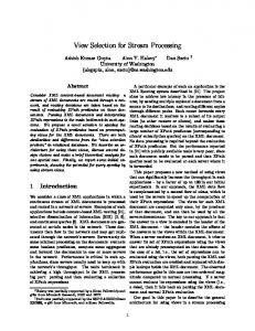
Fig. 1. The robotic application with the set of processing modules (Intelligent processing resources) allowing to map the input from sensors (right side) to the actuators (right side), a controller (CA) selecting the processing modules, and a user feedback (fed to the controller).
The problem framework is shown in Figure 1. A robotic application with a set of sensors and actuators is designed with the goal to keep the user in a happy state as long as possible. The robotic application is specified by a set of sensors and a set of actuators. The mapping from sensors to actuators is done by assigning resources from the Intelligent Processing Resources pool by the controller that receives the feedback from the user. The user, observing the output of the robot, changes its state such as from happy to unhappy, or happy to happy, and the change of state is provided as the feedback to the controller. Let suh be a user state from a set of all possible observable human emotional states Su = {su0 , . . . , suk , s˜u }, with s˜u being the target user (set of) state(s), and let srj be the robot state from the set of all possible robot states Sr = {sr0 , . . . , srp }. Each state sr is represented by an output that corresponds to the full process of mapping a given input to the output in the state srj . In the rest of this paper we use sr for an arbitrary robotic state and su for an arbitrary user state. A configuration is given by the state of the user su ∈ Su and the state of the robotic application sr ∈ {sr0 , . . . , srj }: c(su , sr ). In order to make the problem at least partially tractable and allow further investigation, we simplify further the overall framework. We assume the following conditions: 1) The state of the machine sr changes the state of the human su immediately 2) If a machine state sr does not change the human state su immediately, it is assumed that it will have no effect on later changes on the human state su while the machine remains in the state sr 3) For now, the human state as well as the human state change is considered to be only the application related and it is assumed that the desired state is reachable using the robotic application. The robot changes its state from srj to srk using a state change function f : (sul , srj ) → (sum , srk ). It is assumed that for each robotic state sr there is a corresponding change in human state given by suj = (sui , sr ). But following condition 1,
the human state change caused by robot state change is not necessarily observable by the robot.
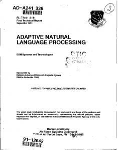
Fig. 2. The problem statement: what is the minimal set of states the robotic controller has to go through to make the user be happy?
Figure 2 shows the high level of this framework. On the left is a non-terminal user state: s¯u = Su − s˜u and on the right side it the user in the target state s˜u . The change from an non-terminal state to the desired target state can be triggered by various sequence of robotic states (actions). Formally, from the point of view of the robot architecture the goal is specified by: minG (s˜u , sr )} (1) {∀sr ∈ Sr , f |(su , sr ) −−−−→ This means that we are looking for such a function f or a set of functions fˆ = {f0 , . . . , fo } that will in a finite number of steps bring the user from an arbitrary state su to the target desired state s˜u . Using the above introduced notions the problem of changing user state can be expressed as a graph or a discrete path integral. However its complexity and solvability depends on how well the human emotional states can be perceived and distinguished. Thus we first analyze the problem from two different point of views: a multi-valued feedback and a binary feedback. This results in a formulation of the problem similar to the one introduced in Benioff [4] and allows to precisely define the Human State Problem. A. Multiple-valued feedback Figure 3 shows an example graph mapping all possible transitions in k robot-steps from the user state suk to s˜u . This means that for a given human state this graph represents all possible state change functions that will allow a k-step user satisfaction. Each node in the graph represents a user state and each path between two nodes is a state change triggered by the machine output change. Recall that this robot-action induced human-state change is related only to the robot action and not to the environment. Each user-state-change graph is thus directly corresponding to a machine-state-change graph. Thus Figure 3 has a sistergraph of the machine states such as for instance shown in Figure 4. The main difference is that while a single user is represented by the graph from Figure 3, each path in the graph from Figure 4 represents a particular machine-state
suk
sul .. .
···
suj
···
sud .. .
s˜uk
suh
Fig. 3. Example of a k-step graph of user states: from a given user state various different paths to the desired user state are possible but not necessarily known.
graph representing the reachable states can be drawn. An example is shown in Figure 6. We assume that each possible machine-state is drawn only once in the graph; because the graph represents a particular machine-state transition function it guarantees the uniqueness of both the paths as well as of the machine-states.
sr0
···
srj
sri
srh
.. . transition function (a different controller). Also as can be seen in Figure 4 there is one starting node (the initial state) but there is no a final state. This is because the rightmost states in the Figure 4 are not the robots final states, but only states that represents the satisfied user feedback with the initial state of the user being suk .
srk
srj .. .
···
srp
···
sri
srh
.. .
.. .
srf
srl
Fig. 4. Example of k-step graph of machine states: from a given initial state of the machine, various state transitions (different state transition functions) can reach a machine state that would consequently makes the user happy.
Merging the two above graphs, the global representation of the user-side problem is a multi-input single-output graph showing all possible user-states transitions. Figure 5 shows all user state transitions from any initial and non-terminal state to the terminal state in k-machine steps. Each path from the leftmost node to the final node represents a different machinestate transition function. Thus each node from a column in the graph is associated with a different robot state.
sul
···
su0 sud .. .
.. .
.. .
s˜uk
suh suk suj
···
Fig. 5. From all possible user states (that are not the target state) various paths to the final desired state are possible.
Similarly for one machine-state transition function fi a full
srk
srp
srf
Fig. 6. With a single state transition function, a given machine can reach only some state from all possible initial states.
From these various graphs the problem can be seen as a graph minimization problem. We assume that the initial knowledge about the human states is not know. Even with a off-line machine learning approach only a fraction of human states can be mapped and thus most of them still remains unknown. Using this discrete approach we can formulate an objective function that allows to evaluate if the robotic application succeeded or not. This minimization equation takes into account both internal as well as external constraints.
G =G0 + G1 =
p X j=0
mink v(hpK ) + mink b(hp+1 k )
(2)
sat. su = s˜u with mink v(hpK ) being the minimum of steps satisfying internal constraints, mink b(hp+1 k ) being the minimum steps satisfying the external user feedback and s˜u being the target user state. This notation will become clearer and will be more explained in the Section IV. For now, let this equation represent the overall problem, where the minimization is done over the number of changes in the configuration leading from an arbitrary user state su to a desired state s˜u . Thus the problem formulated using eq. 2 can bow be defined with respect to number of changes in a reachability graph of a machine. Thus one can ask: what is for a given user graph (unknown) the best machine graph that will require the minimum number of changes and give the user the most satisfaction from the performance? B. Binary feedback In the above defined problem it was assumed that the robotic application can recognize many emotional user states. However it is reasonable to assume that the user feedback might be only binary such as satisfied or un-satisfied. In such case the set of possible user states is the set {su , s˜u }. Thus the graph
transition of the user states now has only two possible states but the same number of possible paths (Figure 7). Observe that in the case where only the binary feedback is available, the feedback acts as the reinforcement signal rather than direct feedback.
2) The user will not change its state proportionally to the change of robotic behavior, because its emotional state is mainly based on the content of the robot’s output rather than on the robot’s behavior it self. srh
su
su .. .
···
su
···
sri
su .. .
s¯uj
s˜u suj
su suk
Fig. 7. The user state graph changes using only two user states: the nonterminal state suk and the terminal statesuk ˜ .
Note that the binary user-state tree is an extreme case of the multiple-valued feedback case; in the previously shown userstate graphs the only requirement is that each transition from one user-state to another-user state is triggered by a machinestate change. C. Human Emotional State Data Mining In the previous section we were assuming that condition 3 from Section II was valid. However in real world applications the user providing feedback to the robotic application might not always express its emotional state only as related to the robot task performance. For instance, the application framework illustrated in Figure 1 can be used for an automated Live-performance TV-set. In such case, the actuators control the camera and the microphone and the sensors accept data from the camera and microphone. The output of the camera and the microphone is transmitted to the user via the TV-set. Thus in a particular sport event, the user can be angry at the team in question (game quality) or can be unhappy about the viewing angle of the camera (robot performance quality). In both cases the expression can be the same and the robot is required to identify the proper cause of user state. Our approach to deal with this problem is based on HumanEmotional-State data-mining (HESdm). A user in a given state will show different sensitivity to changed robot’s actions depending whether yes or no he/she was displeased with the robot previous behaviors. For instance, assume that the user is watching a sport game, and is dissatisfied; i.e. either the performance of the players is not satisfactory either the viewing angle is not adequate. By following the conditions 1 and 2 from Section II change in user behavior can be described by two cases: 1) The user will change its state proportionally to the change in robot performance (state). This is the case described by all three conditions 1, 2 and 3 in Section II.
Fig. 8. The human emotional state data mining. The two possible human state changes; the robot changes to a state that either triggers a state of human emotional state or is mostly ignored. This is the trail-and-error approach to determine the relation of user state to the robot’s performance.
These two cases are illustrated in Figure 8. The robot is in the state srh and the human is in the state suj . It can be seen that we assume that the user-state suj was generated as the reaction to the robotic state srh (more or less depending on the content as well). At this point, and depending on the content of the robotic output, the user state is not the desired user state s˜uj . The robot consequently changes the state to sri to determine the reason of the user state. If the user state is only content related, the resulting user state will be s¯uj . The new user state being similar to the previous user state indicates that the user is unhappy because of the content rather than because of the robot performance. In such case the robot can keep the current state until further event either change the user state or particular case of the game will trigger a different robot state. In the opposite case, when the resulting state is suk , the robot can conclude that the user dissatisfaction is related directly to the robot performance and thus a change in robot actions is required. III. T HE PROPOSED
MODEL
Our approach is based on behavioral robotics. Because of the space constraint we only introduce this approach but we do not explain the principles of the behavioral robotics. The interested reader should consult [3] for a comprehensive overview of this approach. A. Behavioral Robotics The main idea of behavioral robotics is to build a robotic processor for a given application by providing a set of behavioral layers (each with a particular sub goal) together with a method for choosing a proper output for a given input. Each behavioral layer is then used to generate motor control in parallel and either one at a time is used as the output (as in subsumption architecture [5], [6] or in competitive architecture
Behavior Arbitration
Sensors
Behavior Activation
[16]) or the control outputs of individual behavioral layers are composed in some way to create a single output state of the resultant robot behavior. This is done using fuzzy logic [20], [1], linear command summation [2], [19], [18] or some other mechanism such as evolutionary algorithms[10], [17], [21], [13], [22] or artificial immune systems [23]. For instance Figure 9 shows a robotic behavioral processor with four behavioral layers. Each layer has a distinctive goal taken from the overall problem definition. The behavior selection mechanism is the subsumption model [6].
Map building Explore Wall following Object Avoidance
Actuators
functional columns (hardware blocks); each column is built from a set of functions (functional modules), from an output buffer, from an activation module and from an arbitration module (Figure 11). The activation module allows to decide where the data input goes - i.e. which function will generate output. The arbitration module allows to select which functional output will be selected as the output of this column. The set of functional modules can be any type of function: from neural network processor to a Fourier transform or a face detection algorithm. The behavioral arbitration module is represented by a MUX letting only one functional module to propagate its output to the output buffer. The activation module is either a DEMUX (propagating the input only to a single functional module) or is completely ignored and thus allows the input data to be propagated to all functional modules (Figure 10). F01
Fig. 9. Example of behavioral robotic processor with four behavioral layers for navigation task.
Input
F00
F0−1
B. Behavioral Matrix Pattern
To address the above introduced problem we designed a hardware architecture that can in real time generate behavioral layers by adaptively combining functional modules. The principles that this platform is based upon are the following: •
•
• •
Each behavioral layer can be build in real time by interconnecting a set of pre-defined functional blocks (functions). Each behavioral layer built in real time is composed from input-activated functions and output-filtered functions. Both valid behaviors and invalid ones can be created The output from each function in a behavioral layer can be based on current or past input values
The proposed hardware architecture is shown in Figure 10. This structure is called a behavioral matrix. It is built from Functional Columns e0
e1
Functional Modules e2
e3
e4
e5
f03
f13
f23
f33
f43
f53
i0 i1
f02
f12
f22
f32
f42
f52
f01
f11
f21
f31
f41
f51
o0 o1
.. .
f00
f10
f20
f30
f40
f50
.. .
f0−1
f1−1
f2−1
f3−1
f4−1
f5−1
f0−2
f1−2
f2−2
f3−2
f4−2
f5−2
f0−3
f1−3
f2−3
f3−3
f4−3
f5−3
ik−2 ik−1
oj−2 oj−1
Behavior = {e0 , e1 , e2 , e3 , e4 , e5 } ∈ {−3, −2, −1, 0, 1, 2, 3} Behaviorallayer1 = {1, −1, 2, −2, 1, 2} Behaviorallayer2 = {0, 0, 0, 0, 0, 0}
Behavioral Activation
θ
2θ
Output
4θ
e0
Behavioral Arbitration
Fig. 11. Example of a functional column with the function activator and the function arbitrator
The output buffer in each functional column allows to be filled with the currently selected functional module output value and thus to propagate sensory input it to the output ot = fj (it ). This can be seen in the case when input data reach a functional column and both the activation and arbitration modules are pointing to the same function. The output buffer can also propagate a past input to the output ot−k = fj (it−k ). This is the case when either the arbitration or the activation modules in a functional column point to a different function; the output obtained on the output will be the value last stored in the output buffer. Observe that using our approach the functionality of each behavioral layer is created automatically in real time by a serial combination of functions. Each function from a column is selected using a control variable {e0 , . . . , e5 } in Figure 10. The output of the last functional column is either propagated to the actuators or can be withheld to be used as a part of the next input. In this manner each functional column can be used as a combinational circuit or as a sequential circuit. IV. C ELLULAR AUTOMATON FOR B EHAVIORAL A RBITRATION
Behaviorallayer3 = {−1, 3, −2, 1, 2, −1}
Fig. 10.
Example of the behavioral matrix robotic processor architecture
The output of the behavioral matrix is controlled by the control variables (as described above). The arbitration of behaviors
thus can be seen as a selection of control variables with respect to a particular set of inputs and a feedback. Because the problem introduced cannot be analyzed from a global point of view, we propose to use an arbitration mechanism based on local rules and feedback. Using local rule based arbitration mechanism we can on one hand build in real time a global representation of the environment based on local rules and on the other hand use computational models requiring less resources. Using a Cellular Automaton (CA) to assign in real time computational resources in the behavioral matrix, saves computational resources (only used functional modules are turned on), uses only local state transition function and as required allows to build a global environment representation. Also and more important, the use of CA for behavior arbitration allow for cyclic sampling of the environment and action generation. The idea behind this approach is the fact that the execution of a task can be done by a sampling through the environment with both various sensors and various actuator actions. This means that a robot with a set of possible actions, can be instructed to solve a particular task by cyclically selecting from a sub-set of these actions and arriving at its goal. The main advantage compared to behavioral robotics for instance is the resource saving; while in standard robotics all resources are computing in parallel at all times, the architecture proposed here allows to selectively activate particular set of computational modules and thus save energy.
Fig. 12. Example of a behavioral controller based application. The first column represents the detector allowing to detect a player, a ball and the audience, the second column shows three different black-box estimators and the last columns are actuator commands. Observe there is one internal feedback from the first column to the controller as well as the external user feedback allowing to change the output of the robotic application.
Figure 12 shows an example of robotic application using the behavioral matrix with three columns controlled by a threecell CA. The application that this processor was designed for is the intelligent TV-set. The purposed is to allow the user to change behaviors of cameras and thus allowing the user to fully enjoy for instance a live sport event. Each functional column has either three or four input functions and thus each of the control cells is considered to use three/four valued logic. The robotic processor has two types of feedback. First, an internal feedback is used to lock the first column; if a given feature is detected the CA will not
change the detection module. A change in the detected feature is triggered only by the global robot state change. Second feedback is coming from the user and allows to force the CA to change its state. Thus if both feedbacks are positive the robot will continue to perform the current operation unchanged. In any other case the CA will evolve according to a local rule until both feedbacks are satisfied. To illustrate the reason of usage of the CA for the real-time behavior arbitration the following example shows how the trail-and error or behavioral arbitration results in minimization of the number of states required to bring user from a nonterminal state to terminal (desired ) state. Example 4.1 (Minimizing path to desired user state): Let M be a robotic application with a CA controller. The state transition function is specified by the reachability graph shown in Figure 13 and is generated using a three-cell neighborhood CA state transition function f . The two dark squares shows the state transitions of interests. In particular the larger square shows an example situation where the user state and the machine state are respectively given by (suk , srj ) Given this initial configuration the machine proceed
Fig. 13.
State reachability graph of machine M.
in changing its state from 023 to 013 and so on until the state 013 generates the user state s˜u which is the target user state. Because the goal of the robot is to satisfy the user as quickly as possible or even to keep the user constantly happy, the robot uses local rule optimization to reduce the number of required steps between the (suk , srj ) and the (s˜u , srj+4 ). This is shown in Figure 14 where the modified state-transition function partially restructured the reachability graph of the machine M. [End of example] The advantages of the CA based robot arbitration concept introduced in this paper seem can be summarized by three
V. C ONCLUSION We presented a problem of HRI called the Human State Problem and showed how it can be partially analyzed and solved using deterministic hardware based approach. For this we illustrated our robotic processor using a CA for adaptive resources selection and showed by example how it can be used for machine learning of robot behavior by modifying the local state-transition function of the CA in real time. The advantages of this approach are: (1) it is designed to be realized in VLSI leading to low cost and low power consumption, (2) it allows a fast switching of behaviors, (3) it uses multi-valued logic and thus leads to fast realizations of behaviors in hardware. The formalization of the HSP problem allows to at least partially to study the possible solutions and propose some solutions.
Fig. 14. Two path minimized by changing single rules in the state transition function.
powerful concepts: the multi-modal-perception [14], [7], [15] decision making, the non-abellian decision making and the sensory noise resistance. To explain these notions let first assume that the robot has a video camera and a set of image processing algorithms: a set of low level transforms such as Sobel, Hadamard, Haar, HOG (Histogram of Oriented Gradients) as well as a set of high level feature extracting tools such as face detection, face tracking, object detection, shape extraction, color tracking and so on. The multi-modal perception is a well know area in robotics and in general it means that a given decision is made on multiple perception sources and levels. This is illustrated with the approach shown in Figure 12 where various sensor sources can be combined as given by the CA cycle of state change. In this case, using the Output-per-final-configuration output generation the output can be generated using the history based approach combining multiple sources of information. The non-abellian decision making is a generalized concept and it means that a sequence of applied behaviors to a given sequence of inputs is not equivalent to the application of another sequence of the same behaviors to the same input sequence. This can be observed from a simple example. Assume a robot is supposed to solve a puzzle consisting in moving blocks around by pushing them. Any action resulting in a block being adjacent directly to the wall does not allow the robot to move that block away from the wall. Such situation can result either from bad planning but also from bad sensory inputsequence evaluation. Because each behavioral layer pursues its own goal and sometimes such goals can lead to mutually exclusive situations, the order of applying of the behavioral layers outputs bears extreme importance. Such choices can allow to explore novel regions or improvise a solution found by mistake.
The purpose of designing such robotic processor is to allow the robot to deal with noise in real environment as well as with extremely complex situations requiring real-time processing. Examples of such environments are for instance human emotional perception, indirect human feedback or general human-robot interaction. The main problem is that in these environments a single sensory input might not be sufficient and more complex sensor processing and general purpose processing might be required. However the processing must be highly adaptive and should allow variations in both inputs and outputs. Thus the CA controlling the robotic processor by larger or smaller cycles can be used to explore/exploit more or less of the given situation for the purpose of achieving its task. For instance analyzing the input only for object detection and face detection will generate a different output than if the same input is analyzed for face detection, motion tracking and emotional expression. Obtaining different set of features from the input depends on the states of the CA and on how many different states the CA goes through. Thus it is directly related to the size of the cycles and to the states it goes through within these cycles of states. A common question in this approach is why we propose hardware rather than software implementation? The answer is that it is in hardware where the multi-valued logic can bring power saving and thus is ideal to build small low power behavior based robotic processors. In particular it is interesting for robots that can benefit of having the processing on board as opposed receiving all control commands from a computer through a wireless link. As in general the main power consumption is from actuators, eliminating an active wireless link can save a lot of power. Also, on board implementation eliminates additional devices that a remote computer needs such as hard drive, memory and so on. Thus from a global point of view an on-board implementation is beneficial for both the power saving as well as real time processing. Moreover, the design is meant to be learn-able - both the control logic as well as the functional modules are to be either learned in real time of programmed before the task. Thus such controller can be reused by simple reprogramming for various low power robots.
Finally the future of this work consists in developing the hardware platform and implementing a learning mechanism so that the most desirable robotic behavior can be obtained for various applications. The proposed multi-valued basis for design algorithm is to be extended in more details so that ideally behaviors specified by simple constraints can be designed using standard Logic Synthesis methods. R EFERENCES [1] E. Aguirre and A. Gonz´alez. Fuzzy behaviors for mobile robot navigation: design, coordination and fusion. Int. J. Approx. Reasoning, 25(3):255–289, 2000. [2] R. Arkin. Motor schema-based mobile robot navigation. International Journal of Robotics Research, 8(4):92–112, 1989. [3] R. C. Arkin. Behavior-Based Robotics. The MIT Press, 1998. [4] P. Benioff. Quantum robots and environments. Physical review. A, 55(2):893–904, 1998. [5] R. Brooks. A robust layered control system for a mobile robot. Robotics and Automation, IEEE Journal of, 2(1), 1986. [6] R. A. Brooks. Intelligence without reason. In Proceedings of the 12th IJCAI, pages 569–595, 1991. [7] B Chandrasekaran. Multimodal cognitive architectures: Making perception more central to intelligent behavior. In AAAI national Conference on Artificial Intelligence, pages 1508–1512, 2006. [8] A. R. Damasio. Descarte’s Error: Emotion, Reason and the Human Brain. Picador, 1994. [9] A. R. Damasio. Looking for Spinoza. Picador, 2004. [10] M. Dorigo and U. Schnepf. Organisation of robot behaviour through genetic learning processes. In Fifth IEEE International Conference on Advanced Robotics, pages 1456–1460, 1991. [11] P. Ekman. Facial expression and emotion. American Psychologist, 48(4):384–392, 1993. [12] P. Ekman. Basic emotions, chapter 3. Wiley, New York, 1999. [13] B. D. Eldridge and A. A. Maciejewski. Using genetic algorithms to optimize social robot behavior for improved pedestrian flow. In IEEE International Conference on Systems, Man, and Cybernetics, pages 524– 529, 2005. [14] M. P. Hollier, A. N. Rimell, D. S. Hands, and R. M. Voelcker. Multimodal perception. BT Technology Journal, 17(1):35–46, 1999. [15] M.H. Luerssen, T.W. Lewis, R.E. Leibbrandt, and D.M. Powers. Adaptive multimodal perception for a virtual museum guide. In 3rd Workshop on Artificial Intelligence Techniques for Ambient Intelligence, 2008. [16] P. Maes. The dynamics of action selection. In Proceedings of the 11th International Joint Conference on Artificial Intelligence, 1989. [17] C.H. Messom and M.G. Walker. Evolving cooperative robotic behaviour using distributed genetic programming. In Control, Automation, Robotics and Vision, 2002. ICARCV 2002. 7th International Conference on, volume 1, pages 215–219 vol.1, Dec. 2002. [18] M. Nicolescu, O.C. Jenkins, and A. Olenderski. Behavior fusion estimation for robot learning from demonstration. In IEEE 2006 Workshop on Distributed Intelligent Systems (DIS06), pages 31–36, 2006. [19] A. Olenderski, M. N. Nicolescu, and S.J. Louis. A behavior-based architecture for realistic autonomous ship control. In Sushil J. Louis and Graham Kendall, editors, CIG, pages 148–155. IEEE, 2006. [20] A. Saffiotti. Fuzzy logic in autonomous robotics: behavior coordination. In Sixth IEEE Intl. Conference on Fuzzy Systems (FuzzIEEE’97, pages 573–578, 1997. [21] Y. U. Takaya and T. Arita. Situated and embodied evolution in collective evolutionary robotics. In In Proc. of the 8th International Symposium on Artificial Life and Robotics, pages 212–215, 2003. [22] Y. Wang, S. Li, Q. Chen, and W. Hu. Biology inspired robot behavior selection mechanism: Using genetic algorithm. In Bio-Inspired Computational Intelligence and Applications, pages 777–786. 2007. [23] Y. Watanabe, A. Ishiguro, Y. Shirai, and I. Uchikawa. Emergent construction of a behavior arbitration mechanism based on the immune system. Advanced robotics, 12(3):227–242, 1998.