VOL. 11, NO. 6, MARCH 2016
ISSN 1819-6608
ARPN Journal of Engineering and Applied Sciences ©2006-2016 Asian Research Publishing Network (ARPN). All rights reserved.
www.arpnjournals.com
ADAPTIVE SLIDING MODE CONROL WITH RADIAL BASIS FUNCTION NEURAL NETWORK FOR TIME DEPENDENT DISTURBANCES AND UNCERTAINTIES Mst. Nafisa Tamanna Shanta and Norsinnira Zainul Azlan Department of Mechatronics Engineering, International Islamic University Malaysia, Jalan Gombak, Kuala Lumpur, Malaysia E-Mail:
[email protected]
ABSTRACT A radial basis function neural network (RBFNN) based adaptive sliding mode controller is presented in this paper to cater for a 3-DOF robot manipulator with time-dependent uncertainties and disturbance. RBF is one of the most popular intelligent methods to approximate uncertainties due to its simple structure and fast learning capacity. By choosing a proper Lyapunov function, the stability of the controller can be proven and the update laws of the RBFN can be derived easily. Simulation test has been conducted to verify the effectiveness of the controller. The result shows that the controller has successfully compensate the time-varying uncertainties and disturbances with error less than 0.001 rad. Keywords: radial basis function network, adaptive control, sliding mode control, time-varying uncertainties and disturbances, robot manipulator.
INTRODUCTION Robot manipulators are being used in a wide variety of manufacturing and technical applications. They are used in dangerous environments such as handling of hazardous materials in nuclear plants, chemical and gas polluted surroundings, and dangerous mining areas. They are also used in many places where human operation is not suitable. In this application, the robot manipulator is subjected to constant and time-varying uncertainties including payload, friction and disturbances. These uncertainties deteriorate the performance of the manipulator. Therefore, it is necessary to design and formulate a controller which can cater with all constant and non-constant uncertainties. In the last few decades, many researchers have formulated some controller to overcome the problems including adaptive control, Sliding Mode Control (SMC), intelligent control and combination of adaptive and sliding mode control [1-6]. A Radial-Basis Function Network (RBFN) is a branch of neural network which performs good to control the dynamics system. RBFN possesses great mapping ability and has a similar feature to the fuzzy system. The Radial-Basis Function Network can improve the control performance even in the presence of large uncertainty of the system. There are some advantages of RBFN such assimple structure, fast and computationally efficient. To get the better performance, the neuron numbers, the average and width of the radial basis function (RBF) and the weights must be selected carefully. In [7], a robust adaptive trajectory tracking SMC based on RBFNN proposed to control of two links Cleaning and Detecting Robot Manipulators which can cater for mass variation, external disturbance and modelling uncertainties. It is used due to its simple network structure and faster learning capacity. The proposed control strategy can also reduce the chattering
phenomenon and good robustness in the trajectory tracking control. However, this controller is design based on the torque input. In [8], a SMC based RBFN is used where the proposed controller shows satisfied performance in the case of 2-DOF robot manipulators. Radial basis function uses curve fitting mode to obtain the nonlinear mapping. By choosing a suitable Lyapunov theorem, the update law and sliding-mode switching gain can be obtained. In [9], the radial basis function network based sliding mode controller is introduced, which is a combination of radial-basis function network and adaptive sliding mode controller. The stability is proven by Lyapunov theory. SMC is used to eliminate the chattering and control an SMA actuator. The simulation results showed the effectiveness of the controller in three different signals such as- multi-step, sinusoidal and triangle. Lee and Choi [10] considered an Adaptive Neurocontroller with Radial Basis Function Network for robot manipulators. In previous work [11], a Function Approximation Technique (FAT) based adaptive sliding mode controller is used to compensate time varying uncertainties. The controller use Fourier series to approximate the uncertainties. This technique requires number of basis function and as a result it consumes high computational effort. Therefore, in this paper, a new Radial Basis Function Neural Network (RBFNN) based Adaptive Sliding Mode controller is designed for a robot manipulator which can carry unknown time-varying payload and also unknown disturbances and friction. The RBFN based adaptive SMC uses a low number of neuron or basis function and more computationally efficient. The contribution of this paper is the voltage-based control law design to compensate for unknown time-varying uncertainties with the utilization of RBFN as the basis function. Simulation test results under three different cases have been conducted and the controller has successfully
4123
VOL. 11, NO. 6, MARCH 2016
ISSN 1819-6608
ARPN Journal of Engineering and Applied Sciences ©2006-2016 Asian Research Publishing Network (ARPN). All rights reserved.
www.arpnjournals.com driven the robot manipulator to track the desired trajectory despite of the presence of time-dependant uncertainties and disturbances. This paper is organized as follows, the structure of RBFN is described, next the dynamic model and the controller design of the proposed controller is presented in the following sections. The results of the simulation are the discussed and finally conclusion is drawn.
M ( x ci y Wi exp 2 2 i 1
) , i 1,2,3.... N
( x ci 2 2
where, Z exp and
(2)
) , ci are called average
is called the width of the hidden layer.
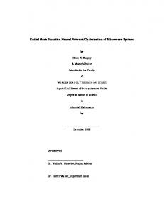
THE STRUCTURE OF RBF NEURAL NETWORKS Radial-basis function network (RBFN) is one type neural network. There are three layers in RBF networks; which have the input layer, hidden layer and output layer. The unique feature of the RBF network is the process performed in the hidden layer. The configuration of RBFN is shown as in Figure-1. [12]
can be represented as Wˆ Z ( t ) ; where, Wˆ is the approximation of W. The approximation error between the estimated and actual range can be written as
Figure-1. Structure of basic RBF neural network
Figure-2. Structure of proposed RBF neural networks.
Usually the input vector is denoted by [ x1
x2 …
x n ], output layer as [ y1 y 2 … y n ]. The advantages of this RBFN is their design simplicity, great speculation, solid tolerance to various noises coming with inputs and real time data picking up capability. The characteristics of RBF systems make it extremely suitable for adaptable control frameworks. In this study, RBFN is used for controlling the robot manipulator with 3-DOF subjected to time varying uncertainties and disturbances. Therefore, in this study, the RBFN input vector is chosen as [e e ], where e is the tracking error and e is the rate of error vector. The output y is representing as Wˆ Z , the architecture of a RBF neural network is given by [7]
Wi is called weights. The estimation of the uncertainties
~ W W Wˆ
DYNAMIC MODEL OF A 3-DOF ELECTRICAL ROBOTIC MANIPULATOR Using Lagrange equation, the mathematical model of an 3 degree of freedom (DOF) robotic manipulator considering the unknown payload and disturbances, can be represented
X AX (t ) BU (t ) d (t )
i 1
Then, rewrite the equation (1),
(1)
(4)
where, X (t ) is a 3 1 state vector and U (t ) is the 3 1 input vector. A is a 9×9 system matrix, B is a 9×3 input matrix and d ( t ) is a 3 1 vector of the unknown external disturbances. The measured and desired state variables can be represented by vector X and X d respectively-
M
y Wˆ Z
(3)
T X 1 1 1 2 2 2 3 3 3
(5)
Xd 1d 1d 1d 2d 2d 2d 3d 3d 3d
T
and
4124
(6)
VOL. 11, NO. 6, MARCH 2016
ISSN 1819-6608
ARPN Journal of Engineering and Applied Sciences ©2006-2016 Asian Research Publishing Network (ARPN). All rights reserved.
www.arpnjournals.com
A A A
(7)
B B B
(8)
A and B are the 9 9 and 9 3 nominal matrices respectively, A and B are the 3 3 unknown matrices of A and B respectively, which contains the time varying uncertainties, including the payload, m L coulomb friction torque, F ci and viscous friction torque, V ci .
The summation of the uncertain elements can be written as WZ where ε is the approximation error in the RBFN expression. Let’s consider the following control law
u ( t ) u eq u PI u RBF u a
The RBF neural networks update law can be set as:
The element of A and B contains all the electrical parameters:
2 Wˆ
where, J mi : moment of inertia for ith motor (kgm2)
and
mi (t ) : angular displacement for ith motor (rad) Bvi : viscous friction coefficient for ith motor (Nm/rad/s) k ti : torque constant for ith motor (Nm/A)
(12)
2
2 ( t ) 1 1 K
(13)
0
3 0
are the real positive
Referring to Equation. (4), u eq is the equivalent
Ri : armature resistance for ith motor (Ω)
control terms is considered for the approximately known nominal system X AX BU (t ) in the absence of the disturbances. Differentiating Equation. (9),
iai (t ) : armature current for ith motor (A) TLi (t ) : load torque for ith motor (Nm) Vi (t ) : voltage input to the ith actuator (V) and i=1,2 and 3. The detailed expression for the element of A and B can be found in [13]. CONTROLLER DESIGN AND STABILITY PROOF In this section, a new Sliding Mode ControlRadial Basis Function Network (RBFN) based adaptive controller is designed for the robot manipulator for trajectory tracking. The sliding mode control is chosen due to its robustness and RBFN is used for computationally efficient. At first, a standard proportional integral sliding surface is chosen in this study, where,
( t ) 2 1 e 2 2 e
(14)
Utilizing Equation. (14) by , (t ) can be written as: d
Substituting
e X X
2 ( t ) 2 1 ( X X d 2 e ) 2 1
(15)
substituting X A X B U (t ) Equation. (15), and equating (t ) to 0, Now,
in
(9)
(t ) is a n 1 vector, 1 and 2 are n n diagonal positive definite matrix and n is an integer number. The tracking error X X d can also be denoted as
e , where e X X d . The time varying uncertainties can be expressed by the RBFN in Equation. (1) and (2) where WZ AX BU ( t ) d ( t )
( t ) 1 1 Z
constants.
Li : armature inductance for ith motor (H)
(t ) 2 1 ( X X d ) 2 2 ( X X d ) dt
ˆ 0
T
where, 1 , 2 , 3 , K
k vi : back emf constant for ith motor (V/rad/s)
(11)
(t ) 21 ( X X r ) 21 ( A X B U (t ) X r ) 0 (16) e where, X r X d 2 2
2 1
(17)
Rearranging Equation. (16) by putting U ( t ) and assigning this term as u eq ,
(10)
u eq B 1 ( X r A X )
(18)
4125
VOL. 11, NO. 6, MARCH 2016
ISSN 1819-6608
ARPN Journal of Engineering and Applied Sciences ©2006-2016 Asian Research Publishing Network (ARPN). All rights reserved.
www.arpnjournals.com The term u PI is a PI type controller and it is necessary to enhance the close-loop stability and improve the transient performance. u PI B
1
K B
1
K ( 2 1 e 2
2
edt )
(19)
where K is a diagonal positive definite constant matrix The term u RBF is responsible for compensating the disturbances and is defined as based on the estimated disturbances
V 2 T 1 1 ( A X (t ) B U (t ) AX Bu d (t )) (26) ~ 2 1 T 1 X r 2W T Wˆ ~0 3ˆ 0 Utilizing Equation. (22), Equation. (26) can be simplified as:
~ V 2 T (t ) 1 1 K (t ) W T ( 2 T 1 1 Z 2Wˆ ) (27) 2 T ~ ˆ 2 ˆ 1
1
0
3
0
1
1
0
Equation. (27) can be simplified as: u RBF
B Wˆ Z
(20)
1
The term Wˆ Z represents the uncertainties and unknown disturbances of the RBFN as displayed in Figure-2. The term
u a is the term to eliminate the
V 2 T ( t )1 1 K ( t ) W T (2 T 1 1 Z 2Wˆ ) (2 ˆ ) 0
1
1
3
(28)
0
Substituting Equation. (12), (13)- the equation with the update law , Equation.(28) becomes-
approximation error ua B 1 K 0ˆ 0 [sgn( ( t ))]
(21)
where K 0 is a 3 3 diagonal positive definite constant matrix and ˆ 0 is the estimation of
0
which is
the upper bound of d (t ) where,
(29)
V 2 T 1 1 K
Since V 0 and V 0 , ( t ) 0 and e 0 as using Barbalat lemma t The block diagram of the proposed controller is shown in Figure-3.
is the function approximation error
Hence, the following control law is proposed in this study u (t ) B 1 ( X r A X K Wˆ Z K 0ˆ 0 [sgn( )]) (22)
To guarantee the stability of the proposed controller, consider the following Lyapunov function: V (t )
1 T 1 1 ( t ) 1 ( t ) W T 2W 0 3 0 2 2 2
(23)
where 1 , 2 , 3 are the real positive constant and ~ o is
~
0
0
ˆ 0
(24)
Differentiating Equation. (22) with respect to time, the following Equation. can be obtained
~ 2 V T1 ( 2 1e 2 e) 2W T Wˆ ~0 3ˆ 0
(25)
Now, utilizing X AX ( t ) BU ( t ) d ( t ) and substituting Equation. (7) and Equation. (8) in Equation. (25), yields
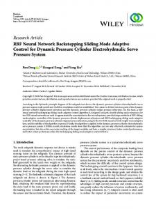
Figure-3. Block diagram of the proposed controller. SIMULATION RESULTS The simulation results show the effectiveness of the proposed controller. The proposed controller caters for various uncertainties including time-varying payload, friction and external disturbances. The robot manipulator is required to follow the desired trajectory, di (t ) with i=1,2 and 3, where,
(0) i di (t ) i 2
2t 2t 2 sin 2 , i (T )
(30)
4126
VOL. 11, NO. 6, MARCH 2016
ISSN 1819-6608
ARPN Journal of Engineering and Applied Sciences ©2006-2016 Asian Research Publishing Network (ARPN). All rights reserved.
www.arpnjournals.com
i (0) is the initial position, i (T ) is desired final destination and i = i (T ) - i (0) , where i= 1,2,3. The graph of desired joint position trajectory is shown Figure-4. In all cases, the controller parameters are tuned as 1 50 , 2 1 , 1 2 3 1 , K= 337 and the amount of coulomb friction torque of Fc1 20 , Fc2 5
Fc3 6 Nm and viscous friction torque Vc1 6 ; Vc2 5.5 ; Vc3 5.5 for joint 1, 2 and 3 respectively.
and
The number of neurons is chosen as 3 for all the simulation cases.
(b)
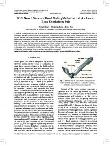
(c) Figure-4. Desired joint position profile for all 3 joints. From the graph, Figure-5 (a)-(c) shows the position response of the robot manipulator where the payload mass and disturbance is considered as m L 5 5.5 sin 5 t and d (t ) 5.5sin 5t respectively. The figure shows the comparison between actual and desired trajectory position according for joint 1, 2 and 3 of the robot manipulator. The result shows that the proposed controller drives the robot accurately despite the sinusoidally varying payload mass and disturbance.
Figure-5. Tracking performance of the proposed controller when the pay load and disturbance is considered as time-varying sinusoidal function. The controller is tested with random time-varying payload and noise disturbance with average=4 and variance=6. From Figure-6 it can be observed that, the actual position trajectory successfully followed the desired position trajectory for all 3 joints and the maximum error is less than 0.001 rad. The result verifies that the propose controller is robust against the unknown friction and timevarying uncertainties.
(d) (a)
4127
VOL. 11, NO. 6, MARCH 2016
ISSN 1819-6608
ARPN Journal of Engineering and Applied Sciences ©2006-2016 Asian Research Publishing Network (ARPN). All rights reserved.
www.arpnjournals.com
(e)
(f)
(g)
(h)
Figure-6. Tracking performance of the proposed controller when the pay load is random time varying and disturbance is considered as Gaussian noise. The result in Figure-5 and Figure-6 also show that the RBFN based adaptive sliding mode control requires low number of neurons or basis function to produce an accurate position trajectory tracking, compared to the function approximation technique proposed in [11]. The average and variance of the noise has been increased to evaluate the limit of effectiveness of the controller with 3 RBFN neuron. From the simulation, it has been the found that the adaptive sliding mode control with 3 neurons works well on noises with maximum average= 40 and maximum variance=60. Figure-7 shows that the number of neurons is sufficient when the average and variance of the noise are 56 and 70, which are greater than the maximum limit.
(i) Figure-7. Tracking performance of the proposed controller when the pay load is random time varying and disturbance is considered as Gaussian noise where the average and variance are greater than the maximum limit. CONCLUSIONS In this paper, a RBF neural network based sliding-mode controller is proposed to control a 3-dof robot manipulator. The controller is robust against the time-varying uncertainties and disturbances where the tracking error is less than 0.001 rad. It gives good result three number of neurons. Future works involves the
4128
VOL. 11, NO. 6, MARCH 2016
ISSN 1819-6608
ARPN Journal of Engineering and Applied Sciences ©2006-2016 Asian Research Publishing Network (ARPN). All rights reserved.
www.arpnjournals.com hardware experimental test of the develop RBFN based adaptive sliding mode controller.
REFERENCES [1] P. R. Pagilla and M. Tomizuka. 2001. An adaptive output feedback controller for robot arms: stability and experiments. Automatica. 37(7): 983-995. [2] M. Zeinali and L. Notash. 2010. Adaptive sliding mode control with uncertainty estimator for robot manipulators. Mechanism and Machine Theory. 45(1): 80-90. [3] A. C. Huang and M. C. Chien. 2010. Adaptive control of robot manipulators: a unified regressor-free approach. World Scientific.
IEEE Transactions on Industrial Electronics. 51(3): 711-717. [11] M.N.T. Shanta and N.Z. Azlan. 2015. Function Approximation Technique Based Sliding Mode Controller Adaptive Control of Robotic Arm with Time-Varying Uncertainties. IEEE International Symposium on Robotics and Intelligent Sensors (IRIS 2015). (In press) [12] N. Sundararajan, P. Saratchandran, and Y. Li. 2013. Fully tuned radial basis function neural networks for flight control. vol. 12: Springer Science and Business Media. [13] JHS. Osman. 1990. Modeling and control of robot manipulators. Dissertation, city university London.
[4] W. Gueaieb, F. Karray, and S. Al-Sharhan. 2007. A robust hybrid intelligent position/force control scheme for cooperative manipulators. IEEE/ASME Transactions on Mechatronics. 12(2): 109-125. [5] Z. Li, C. Yang, and Y. Tang. 2013. Decentralised adaptive fuzzy control of coordinated multiple mobile manipulators interacting with non-rigid environments. IET Control Theory and Applications. 7(3): 397-410. [6] J. Peng, Y. Wang, W. Sun, and Y. Liu. 2006. A neural network sliding mode controller with application to robotic manipulator. The Sixth World Congress on Intelligent Control and Automation, WCICA. pp. 2101-2105. [7] C. Van Pham and Y. N. Wang. 2014. Robust Adaptive Trajectory tracking sliding mode control based on neural networks for Cleaning and Detecting Robot Manipulators. Journal of Intelligent and Robotic Systems. 1-14. [8] H. C. Lu, C. H. Tsai, and M. H. Chang. 2010. Radial basis function neural network with sliding mode control for robotic manipulators. IEEE International Conference on Systems Man and Cybernetics (SMC). pp. 1209-1215. [9] N. T. Tai and K. K. Ahn. 2010. A RBF neural network sliding mode controller for SMA actuator. International Journal of Control, Automation and Systems. 8(6): 1296-1305. [10] M.J. Lee and Y.K. Choi. 2004. An adaptive neurocontroller using RBFN for robot manipulators.
4129