Specifically, our main contributions consist of re- ... Section 5, the advanced animation techniques, and ... segment is individually specified and animated by.
Advanced virtual humanoid animation framework based on the MPEG-4 SNHC standard M. Preda and F. Prêteux ARTEMIS Project Unit, Institut National des Télécommunications 9 Rue Charles Fourier, 91011 Evry Cedex, France Email: {Marius.Preda, Francoise.Preteux}@int-evry.fr 1. Introduction The ISO/IEC 14496 standard issued in December 2000 specifies a normative framework and a set of tools to animate virtual avatar. Efficiency of such a standardized face and human body description and animation has been widely demonstrated all along the standardization process [1] and more recently in specific applications developed and implemented by several companies [2], [3]. However, achieving realistic animations requires a lot of efforts during the modeling stage, specifically for accurately and efficiently handling 3D object deformations. As all the animation parameters have to be explicitly defined and transmitted for each frame, such a flexibility as instantiating and transmitting only key frame animation parameters, is not supported. In addition, a high level animation description, as provided by a gesture analysis system [4], [5], involving a subset of the animation parameters cannot be specified within the standard. This paper addresses the issue of defining an advanced virtual humanoid animation framework based on the MPEG-4 standard and overcoming the above-mentioned constraints and limitations. Specifically, our main contributions consist of remodeling the MPEG-4 avatar in order to easily manage its deformations and of supporting the intuitive functionalities which are high level gesture description related. Specific methods for representing and manipulating the avatar structure and for achieving the avatar animation by using temporal and/or spatial subsets of animation parameters are proposed. Section 2 introduces the SNHC MPEG-4 framework and describes the MPEG-4 avatar object representation. Section 3 deals with the re-modeling of the MPEG-4 avatar as a global seamless-based representation. Section 4 addresses the interpolation techniques as compression and animation editing tools. In Section 5, the advanced animation techniques, and specifically inverse kinematics, are addressed. 2. The SNHC MPEG-4 framework The human body consists of anatomical segments (such as upperarm, forearm, hand, skull, hind foot…) which are connected to each other by joints (shoulder, elbow, wrist, skull base, ankle…). Animating the humanoid requires to access joints and to alter joint angles. The MPEG-4 Body Object is a hierarchical graph [6] consisting of nodes associated with anatomical segments and
edges defining relationships between the segments. Two nodes of the hierarchical graph are said to be connected if there exists a joint shared by the anatomical segments represented by the two graph nodes. In addition, the hierarchical graph is oriented. Each node has a unique parent and possibly, several children nodes. Each anatomical segment is individually specified and animated by means of two distinct bitstreams, referred to as Body Definition Parameters (BDPs) and Body Animation Parameters (BAPs). BDPs control the intrinsic properties of the anatomical segment, namely its geometry (3D point coordinates and connectivity) and photometric attributes. The definition and the syntactic representation of the BDPs are based on the H-Anim 1.1 specifications [7]. Namely, two kinds of nodes are specified: (1) the Segment Node refers to 3D geometry and color attributes of the anatomical segment and (2) the Joint Node provides the 3D rotation center of the segment. BDPs are avatar-specific; hence, the overall morphology of an avatar can be readily altered by overriding the current BDPs. BAPs define the extrinsic properties of a segment, i.e. its 3D pose with respect to a reference frame attached to the parent segment. As opposite to BDPs, BAPs are meant to be generic: if correctly interpreted, a given set of BAPs will produce perceptually reasonably similar results, in terms of motion, when applied to different avatar models specified by their own BDPs. More sophisticated aspects dealing with realistic 3D deformations induced by model animation (muscle contraction, clothing folds and adjustments ...) [8] are achieved by instantiating Body Animation Tables (BATs). BATs specify a list of vertices of the 3D mesh model which undergo non-rigid motion and define for each vertex the displacement field as functions of BAPs. BATs are body model-dependent. Therefore, generating BATs requires a specific modeling stage which is highly interactive and time consuming. The most undesirable effect when dealing with animation without specifying BATs results in broken mesh at the joint level between two segments. We therefore propose to restructure the MPEG-4 avatar to overcome this limitation. 3. Re-modeling the MPEG-4 avatar In order to provide a realistic avatar animation without specifying BAT information, we propose to re-model the MPEG-4 compliant avatar within a
seamless shape framework. The principle consists of defining a new descriptive structure made of: (1) a global seamless mesh which is the 3D mesh object specified by the geometry properties and the attributes of the initial MPEG-4 mesh avatar. The new structure describing the skin appearance is implemented as an ArticulatedModel Node; and (2) a set of Bone Nodes which are the edges of the dual graph of the MPEG-4 hierarchical graph. The dual graph is called avatar skeleton and its edges, bones. Given a bone, the related Bone Node also specifies all the points of the global seamless mesh which are affected by the bone motion. The descriptive structure (Table 1) is generic enough to describe any kind of articulated model. ArticulatedModel { ExposedField SFString version “” ExposedField SFString name "" ExposedField MFString info [] ExposedField MFNode bones[] ExposedField MFNode segments [] Field SFVec3f bboxCenter 0 0 0 Field SFVec3f bboxSize -1 –1 –1 ExposedField SFNode AMVerticesCoord NULL ExposedField MFNode AMSkin [] exposedField MFNode AMIndexedSetBone NULL } Table 1a: ArticulatedModel Node representation. Bone { ExposedField SFVec3f position 0 0 0 ExposedField SFRotation orientation 0 0 1 0 ExposedField MFNode children [] ExposedField SFInt32 identifier 0 ExposedField MFInt32 affectedVertices [ ] ExposedField MFFloat affectedVertexWeights [ ] } Table 1b: Bone Node representation.
Table 1: Generic structure of an avatar within a seamless-based representation.
Specifically, the new fields introduced in the descriptive structure are: • AMVerticesCoord which specifies the 3D coordinates of all the vertices of the mesh, • AMSkin which defines the skin topology (connectivity) and the attributes (color, texture...) and which refers to AMVerticesCoord for the vertex geometry, • AMIndexedSetBone Node which contains information related to how a vertex specified in AMVerticesCoord is connected to the skeleton. This node is implemented as follows: AMIndexSetBone { exposedField MFVect exposedField MFVect }
contains the list of seamless mesh vertex indices affected by the bone motion, and • AffectedVertexWeights which is related to a bone and contains the list of weight values which reflect the manner the bone affects the vertices. From a practical point of view, the potential redundancy of the proposed descriptive structure is exploited in order to provide a more compact representation of the bone/vertex influences. In order to achieve the avatar re-modeling, we have implemented a connectivity-based concatenating procedure of the 3D meshed MPEG4 avatar, conditionally to the MPEG-4 hierarchical graph. The principle is to create (triangular) facets between joint level vertices of adjacent mesh components and to describe the global seamless mesh as two lists of unified vertices and topologically consistent facets. Each Bone Node then contains a list of pointers to the 3D points belonging to the initial Segment Node and to the influence zone of the related joint within the parent Segment Node. The influence zone is adaptively determined with respect to the degree of freedom of the joint and the local avatar morphometry.
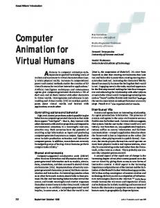
a) Bone B0, related joints and associated mesh points.
b) Adjacent bones to B0 and associated mesh parts.
c) Joint influence zones.
d) vertex weights according with labeling procedure AMboneIdentifier AMboneWeights
[] []
AMboneIdentifier is a multiple vector, each component is a vector associated with one vertex only. The first vector component contains the subset of bones which affect the vertex #0 in the mesh. Similarly, the multiple vector AMboneWeights contains for each vertex the weight values related to the bones specified in the AMboneIdentifier. For each vertex, the AMboneIdentifier and AMboneWeights have the same number of elements. • affectedVertices which is related to a bone and
Figure 1: Vertex labeling procedure and weights computation.
The main steps of the algorithmic procedure (Figure 1) consist in: 1. Extracting joints and labeling mesh points related to a given bone B0, as B0 initially affected points; 2. Aligning the adjacent bones with respect to B0 and labeling mesh points to adjacent bones; 3. Defining the influence zones of the joints of B0 as spheres centered on each joint with a radius ρ defined according to the biomechanical properties and morphometrical constraints [9].
4. Computing the weight values for each vertex M. Three configurations then occur: • for M belonging to the B0 initially affected point set and not included in the spheres, the weight value is set to 1, • for M belonging to the spheres, the weight value is expressed as follows: w=0.5⋅
ρ +αd ρ
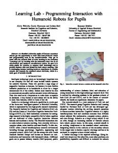
(1) where d is the Euclidean distance from M to the joint center and α equals 1 if M belongs to the B0 initially affected point set and –1 if not, • for M not fulfilling the previous two configurations, the weight value is set to 0; 5. Normalizing the weight vector for each vertex. BAPs are now attached to the Bone Nodes and no more to Segment Nodes as in MPEG-4. When applying BAPs to the whole set of bones, the new 3D position of a point of the global seamless mesh is computed as a weighted combination of the related bones motions. The above-described method has been applied to animate several MPEG-4 avatars defined by different BDPs sets. The animation parameter data set used in our experiments are made of the BAPs corresponding to the alphabet letters expressed in American Sign Language and gestures in British Sign Language obtained by automatically converting information provided by a specific motion capture system [10]. Results obtained (Figure 2) show the ability and the robustness of the proposed method to achieve animation of different avatars with a visual quality similar to the one yielded when using BATs instantiation. In addition, the animation procedure remains fully MPEG-4 compliant. Therefore, an MPEG-4 decoder can be integrated without any changes making possible to address the issue of data compression and transmission.
MPEG-4 compliant avatar animation without BATs
editing tools and (2) animation compression techniques. In the first case, the objective is to provide natural-like gestures and motions from a limited number of key frames which are known. In the second one, the goal is to achieve the best compression rate with a minimal error on the interpolated animation data computed from some key frames dynamically selected within the interpolation procedure. MPEG-4 standard allows to animate the avatar by specifying the entire set of animation parameters for each frame. Usually, high level motion description systems like sign language notation systems define movements by specifying either the initial and final positions, in the case of simple motions, or the initial position and a trajectory, in the case of complex motions. It is also possible to describe a motion by specifying several key frames. In this paper, we address the issue of a high level animation description and propose some interpolating methods for achieving the avatar animation by using temporal samplings of animation parameters. The principle consists in automatically computing the BAPs associated with the intermediate frames. BAP file contains the joint angles defined as SFRotation of VRML with the only difference that MPEG-4 also standardizes the rotation axis together with the rotation order. Hence, the key issue is the rotation interpolation. Basic linear interpolating techniques, directly applied in the BAP space, have proven to yield bad results [13] leading to non natural motions. Therefore, we propose to convert BAP information into a quaternion representation. Linear interpolation between two quaternions results in a continuous rotation around a fixed axis. In our experiments, both linear and spline-based analysis have been applied. Performances of the interpolation techniques have been first evaluated within the editing tool framework. Visual inspection of the interpolated sign language gestures shows that the quaternion–based interpolation yields realistic and fluid motions provided that appropriate key frames have been selected. When using interpolation as a compression technique, performances obtained have been objectively evaluated by computing the distance between the original BAPs and the interpolated ones and the ratio between the sizes of the initial and interpolated BAP files. d=
N −1
∑(bi −bid )
2
i=0
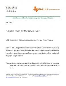
Bone-based avatar animation
Figure 2: Virtual humanoid animation frames.
The generalized form of the seamless-based representation has been submitted [11] for the version 5 of the MPEG-4 standard related to the activities of the AFX [12] group. 4. Key value-based animation Key value-based animation addresses two neighboring but different issues: (1) animation
The efficiency of such a high level animation description has been established and a very compact animation representation provided (gain of up to 80 %). When dealing with several 3D articulated object animation, the cumulative gain is even more important despite the complexity of the scene under study. 5. End-effector driven animation Many applications address the issue of avatar animation by means of relevant subparts of the virtual body. For example, in the case of sign
language description systems, the main interest is focused on hand motions. As arms, forearms and body posture have a relatively less importance, they are not explicitly described in sign language notations. As the complete set of BAPs has to be available in order to use an MPEG-4 compliant player, we propose an automatic method for generating the arm, forearm and body animation parameters starting from the sole 3D hand location. Within the AFX framework, we develop a generic tool allowing to compute the posture of an articulated model by specifying the localization of the end-effectors. The tool is known in virtual animation techniques as inverse kinematics [14] and exploit the biomechanical properties of the avatar. Given a vector q of known joint variables, the forward kinematics issue consisting in computing the position and orientation vector x of the end-effector, is a simple matter of matrix concatenation, and is expressed as x=f(q). The inverse kinematics issue consists in finding the joint variable vector q if the end effector is in a specific position and orientation x: q=f-1(x). Solving the inverse kinematics problem q=f-1(x) is not so simple. The function f is nonlinear, and while there is a unique mapping from q to x, it is not the case when dealing with inverse mapping. There may be many q’s for a particular x. The most common solution methods are based on either matrix inversion or optimization techniques. An appropriate method for real time animation is the so-called Cyclic-Coordinate Descent (CCD) method [15]. It is based on a heuristic method which has been proposed to quickly find an initial feasible solution for a standard minimization-based algorithm. The method attempts to minimize position and orientation errors by varying one joint at the time. Each iteration involves a single traversal of the chain from the most distal link to the base. Each joint variable qi is modified in turn to minimize on objective function. As a solution is obtained at each joint, the end-effector position and orientation are updated immediately to reflect the change. Thus minimization problem to be solved at any particular joint incorporates the changes made to more distal joints during the current iteration. Suppose that the current end-effector position is Pc=(xc,yc,zc), and that the current orientation of the end-effector is specified by the three orthonormals rows of the rotation matrix Oc=( u1c,u2c, u3c)T. The end-effector can be placed as close as possible to some desired position Pd and orientation Od by finding the joint vector q which minimizes the error measure: E(q)=Ep(q)+Eo(q), which is the sum of positional error measure Ep(q)=||Pd-Pc||2 and orientation error measure 3
Eo(q)=∑((u jd ⋅u jc)−1)
2
j =1
Since almost all the BAPs are rotations, the splinebased approach is used in order to represent them and to minimize error E(q). At each joint, the original n-dimensional optimization problem is
reduced to a one-dimensional problem involving just the joint variable qi which admits an analytical solution. The current end-effector frame is updated to reflect the change before proceeding with the next joint. BAPs are easily deduced and generated automatically. The preliminary results obtained for a set of simple and complex motions when dealing with hand as end-effector make us consider the method good enough for use in real time animation application. Within the MPEG-4 AFX framework, as the near perspective, our goal is to use the method to animate any kind of kinematic chain. 6. Conclusion In summary, we address the issue of defining an advanced virtual humanoid animation framework based on the MPEG-4 standard and overcoming the instantiation of BATs and complete BAPs set for all frames. Our main contributions consist of re-modeling the MPEG-4 avatar in order to easily manage its deformations and of supporting the intuitive functionalities which are high level gesture description related. Specific methods for representing and manipulating the avatar structure and for achieving the avatar animation using temporal and/or spatial subsets of animation parameters have been proposed and tested. References7 [1] MPEG-4 IM1 Software Implementation – 3D Player, La Baule, France, October 2000. [2] face2face animation inc., Face animation system, http://www.f2f-inc.com . [3] Computer Graphics Lab, EPFL, MPEG4 Player for HANIM 1.1 Compliant VRML Body, http://ligwww.epfl.ch/ . [4] S. Prillwitz, R. Leven, H. Zienert, T.Hanke, J. Henning, et al. HamNoSys Version 2.0: Hamburg Notation System for Sign Languages – An Introductory Guide. International Studies on Sigh Language and the Communication of the Deaf, Volume 5. University of Hambourg, 1989. [5] Sign Language Web Site at University Lumière Lyon2, http://signserver.univ-lyon2.fr . [6] SNHC Verification Model 9.0, ISO/IEC JTC1/SC29/WG11 W2301, Dublin, July 1998. [7] Specification for a Standard VRML Humanoid, (DRAFT) Version 1.1, http://www.h-anim.org [8] F. Prêteux, M. Preda, T. Zaharia, Preliminary results on hand BAT interpolation, ISO/IEC JTC1/SC29/WG11, M4278, Roma, December 1998. [9] J. Hamill and K.M. Knutzen, Biomechanical Basis of Human Movement, Williams & Wilkins, 1995 [10] Visual system for capture, animation, storage, transmission, www.visicast.co.uk. [11] M. Preda, F. Prêteux, and M. Bourges-Sevenier, Generic articulated model definition and animation, M7116, ISO/IEC JTC1/SC29/WG11, Singapore, March 2001. [12] MPEG-4 Animation Framework eXtension VM 2.0, ISO/IEC JTC1/SC29/WG11 W3922, Pisa, January 2001. [13] M.G. Wagner. Advanced animation techniques in VRML 97, http://vienna.eas.asu.edu/~wagner [14] N. I. Badler, C. B. Philips, B. L. Webber, Simulating humans: computer graphics, animation, and control, Oxford University Press, March 25, 1999. [15] L.C.T. Wang and C.C. Chen. A combined optimization method for solving the inverse kinematics problem in mechanical manipulators. IEE Transaction on Robotics and Automation, Vol. 7(4):489-499, August 1991.