Advanced Visualization (Simulated) Techniques for Modern Construction Management Mohammad Rohania,1
Mizi Fana,2
Chuck Yub
a
Department of Civil Engineering, Brunel University, UB8 3PH, UK International Society of the Built Environment (ISBE), Caldeotte, Milton Keynes, UK
b
Key Words 4D CAD Visualization; Construction Management; On-site Modern Method Construction; Progress Visualization; Simulation; VR & AR Operational Visualization
Abstract Visual simulation has emerged as a key planning tool in built environment because it enables architects, engineers and project managers to visualize construction process evolution before the project starts. This provides an efficient technology for reducing time and cost through planning and controlling resources, machines and materials. On the other hand, construction industry has evolved from traditional to On-site Modern Methods Construction (MMC). Highly efficient and effective on site planning and managing processes are urgently needed, and implementing visual techniques in MMC provide powerful management platform for planning and controlling projects. This project is to simulate operational assembly-line for Onsite MMC by visualization techniques. 4DCAD and simulation of construction operation will combine and superimpose to video that are taken by fix tablets (ipad2) and introduce
1
Ph.D. Candidate, Dept. of Civil Engineering, Brunel University. UB8 3PH, UK. E-mail:
[email protected]
2
Correspondance Author: Professor Mizi Fan, Head of Research, School of Engineering and Design, Brunel University, UYB8 3PH. E-mail:
[email protected]
Augmented Reality scenes of project process in planning stage. For controlling phase, decision making team update schedule and modify simulated operation of construction by comparing 3D- as built project statues and AR animation of planning construction operation constantly. This paper is the first of the series of papers from this study. The paper is firstly to review researches that have been carried out in planning and controlling of construction operation by visualization techniques and secondly to address some issues in existing visualization techniques to MMC.
Introduction Construction industry has evolved from traditional to Modern Method Construction (MMC) during last few decades. Using on-site construction methods has changed toward industrial production line base instead of previous traditional on-site fabrication methods. The decision to build a project by MMC is usually motivated in part by the need to meet deadline of schedule (fast erection), to spenid minimum cost, to minimise waste generation, but to achieve high quality project production. In this way, traditional management methods like
schedule bar chart and critical path methods (CPM) may not be suitable for planning and controlling project resources. Therefore, highly efficient and effective on-site planning and managing methods are urgently needed and also working in a well-planned operational environment can result in maximum potential of project resources. This paper firstly introduces Modern Methods of Construction (MMC) and its definition, advantages and drawbacks. Then, simulation methods and visualization techniques are presented for the planning of construction operation. Visualization techniques have improved and been used by the cooperation of simulation methods for both construction planning and operation. The visualization planning limits to the component evolvement of constructions but the operational visualization depicts the resource interaction of constructions in addition to of the building components. Construction Visualization could also be depicted in both Virtual and Augmented Reality environment. The paper also investigates the different visualization techniques for controlling progress of construction operation.
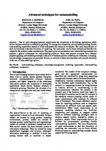
Modern Method of Constructions The term of ‘Modern Methods of Construction (MMC)’ has recently been applied to building industry for characterizing different kind of innovation construction methods. Benefits from using such technologies have been widely studied (e.g. Gibb, 1999; Sparksman et al., 1999; Housing Forum, 2002; Parry et al., 2003; Venables et al., 2004). MMC has been preferred to traditional construction methods as it merits from the reductions in cost, time, defects and risks, less environmental impacts of projects and an increase in forecasting life cycle and benefits of operation [37-38]. MMC is defined as those which provide an efficient management process to generate more products with higher quality in less time compared to traditional construction practices. MMC falls into the following categories: 1. Off-site Manufacture (OSM): The part of the production process that is carried out away from the building site in factory conditions. Examples include: Panel Building Systems; Volumetric (also known as Modular Construction); Hybrid (also known as SemiVolumetric); Sub-Assemblies and Components; 2. Non Offsite Manufacture: innovative methods of construction used on-site and the use of conventional components in an innovative way. This approach encompasses building techniques and structural systems that cannot be placed in the category of off-site manufacture. By way of illustration, examples of non OSM include: Tunnel Form (Figure.1) and Thin-Joint Masonry [8]. It is interesting to note that majority of MMC are off-site methods which transfer from manufactory to project site. The questionnaire survey of the top 100 householders in the UK shows that the advantage of using off-site MMC includes an increasing certainty about cost and time of project; minimizing on-site construction time; having higher quality as well as reduction in health and safety risk [34].
Figure1: Tunnel form construction method [43]
On the other hand, other studies reveal possible higher immediate cost; lack of skilled labours; poor public acceptability and inflexibility of manufacturers to respond construction demand as main drawbacks [37]. This highlights that the planning in off-site methods is vital for realising the advantage of MMC and performing projects in minimum time and cost with higher quality. Using innovative ways in construction operation is as important as designing new ways in construction products. The way that products are put together and construction process evolved is critical factor for project success [9]. As aforementioned, the original aim of MMC is time saving, cost reduction through improving quality and efficiency of construction. Project management for having logic sequence in performing construction activities and resources plays prominent role in achieving project goals. This could only be achieved by visualization and simulation techniques which shall be powerful tools for planning and controlling projects. Advanced visualization techniques can also facilitate better understanding of MMC before starting the project and are able to control MMC according to best alternative plan. In other words, the best alternative for the accomplishment of MMC with functioning all aspects can be achieved by the visualization of simulated construction process. Visualization techniques provide well-organized environment plan of MMC to allocate resources to activities in the best way and perform activities in optimum sequence, and by less time, cost and more quality. Using visualization techniques for managing off-site and modular methods are more common in relation to on-site constructions. Han et al. [21] visualized modular production assembly line by sharing interactive information between visualization, simulation and lean concept. Symphony.Net is used as a simulation tool in the design and analysis of modular construction operations. These simulation processes have performed before and after the execution to foresee the outputs of each scenario. The smart LIFE project [9] is another project for investigating the efficiency, speed of built and construction waste of different on-site modern method construction through quantitative data acquiring. Identifying inefficient activities and valuable improvement in the process of on-site construction is vital by designing modern powerful planning and controlling tools.
Visualization Planning in Construction Management 1.
Simulation
Identifying the best construction scenario among many available options is almost impossible and could be risky, costly and time-consuming, unless each alternative can be modelled and tested by simulation models, and then results are measured by outputs. According to the effect of each scenario, the best one could be selected and revised in simulation environment. Simulation modelling is a tool which enables project participants to experiment the different methods of constructing even without attending project sites. This analysis is able to achieve a better understanding, lower cost and shorten duration. Meanwhile it improves quality and increase certainty in project process. In fact, simulating plays a prominent role in a perspective conception of the automated project planning and controlling. The progress of construction simulation in academic environment has evolved through three periods [1]. The first phase was motivated by the success of CYCLONE. CYCLONE is combined of elements to model project activities, and define discipline activities and their relationships. While CYCLONE is a simple and powerful tool to model cyclic networks, it has problem in modelling resource distribution. It is worth mentioning that CYCLONE has improved in some cases since the beginning of its invention by introducing more capable simulation models (e.g., UM-CYCLONE, ABC and HK-CONISM). The second stage of simulation appeared as advancement programming language and objected-oriented programming. For example, COOPS by Liu and Ioannou (1992), CIPROS by Odeh et al. (1992) and States and ResOurce Based Simulation of Construction ProcEsses (STROBOSCOPE) by Martinez and Ioannou (1994) are objected–oriented simulation environments that use discrete-event simulation (DES) network. STROBOSCOPE is a general purpose simulation programming language for construction operation and includes a series of programming statements which describe a network of interfaced elements. Modelling elements in these systems have charactistics- described through programming definition- that demonstrate how they behave in simulation process. Element charactristics in this model show things such as the duration or priority of an activity, the amount of resource allocated to each activity etc. Simphony introduced by AbouRizk in 1998 is another tool for this stage. In this system, simulation construction operation environment is in both General Purpose Modelling and also Special Purpose Modelling. This time users can create template by collecting elements and linking them together. Each element in this environment has its own behaviour and defines construction activities and events [3]. Simphony and STROBOSCOPE modelling systems are capable of presenting more flexible, extendable and manageable resource environment due to the modern programming languages used. It is interesting that only these
two mentioned construction simulation models are survived at the moment among others. The third stage has been described as the combination of simulation modelling with other tools, e.g. visualization. This is detailed in next section.. Simulation can be helpful in almost all kind of construction processes; there are some situations and areas which this technique is in particular useful for managing construction operation by contrast to traditional methods (e.g., CPM, bar chart). These may include: (1) the situation that is consist of uncertainties and needs probabilistic anticipation for planning; (2) the situation when a project is complicated and need the flexible, detailed and accurate tool rather than traditional ones (e.g. CPM) for modelling all aspects of the project; (3) the construction operation that has repetitive activities; (4) the situation that an integrated solution is needed and user should consider various elements for planning. Simulation tools because of representing multiviews of construction situation (environment, process, products, etc.) enable the user to design effective scenario in preconstruction phase of the project [1]. The main aim of all construction simulators is to maximize the adaptation between virtual operational environment and real execution of projects for efficient planning and controlling. Making automated, detailed and completed modelling of operation is almost impossible unless all real criteria, which are important in construction process, are applied in simulation. Construction Synthetic Environment (COSYE) which developed base on High Level Architecture (HLA) is one of the new methods in modelling and simulating [2]. This system represents more detailed and universal modelling which is able to incorporate components and construction operation models by real situation and restriction. In other hand, this model is capable of merging other software with the simulation model to form a complete platform. In reality, for all aforementioned advancements in simulation operation, the application of simulation models in construction has been more successful in academic environment than in construction industry. Some drawbacks of using simulation modeling in relation to visualization techniques have also been reported, such as, the need to be understood by specialist (i.e. high technology requirement); lack of geometric coordination; low level-details of activities and being difficult in finding the errors of project sequence [19]. 2.
Visualization
Visualization has gained an increasing credibility among researchers in construction and has been considered as one of the four main IT domains in construction [7]. Visualization methods have been emerged as a helpful and coordinator instrument to analyse and communicate simulation results. Visualization of construction process can be divided in the two main categories:
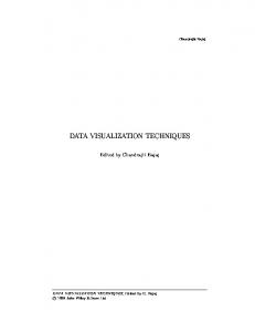
2.1. Activity base visualization(4D CAD) Visualization can sometime be obtained by linking to a 3D CAD model which displays construction component and a construction schedule. This form of the visualization has been recognized popularity as a 4D CAD. Since the early 1990s, there has been a growing interest in four-dimensional computer aided design (4D CAD) for construction project planning. The use of this commercial 4D CAD technology allows the construction planner to produce more precise schedules. Nowadays, 4D CAD are used in a wide range area of construction industry, from micro level activities to macro level ones. There is also a lot of AEC software which support 4D CAD by their application in virtual environment (Figure 2). In comparison with traditional construction planning methods, 4D visualization is able to visualize the development of a project and can be used by variety of project participants with different level of skills and experience. 4D CAD can be useful in different phases of the project from planning to control for different users who are participated in the project. Upper management, high-level executives, construction professionals (project managers) and even workers could all benefit from this method substantially. Some scholars have studied the implementation of 4D CAD by maximizing benefits in infrastructure and commercial projects. They found that 4D is helpful in both project shaping or planning stages and in the construction stages for different levels of project personnel [34].
Figure 2: 4D CAD modeling of construction activities[47]
Hartmann et al. [23] investigated the applicable areas of using 3D/4D models in construction projects according to different phases (design and construction) and types of projects and concluded that 4D models can improve construction management outputs substantially by addressing and solving problems. Two potential areas for improving by 4D CAD in future are considered automatically generated 3D/4D models of as-built project condition by laser scanner or image processing and, time and cost controlling by 4D CAD. In designing phase of construction, numerous researches have tried to attain numeric data and quantitative information by 4D CAD to plan a project [29]. Jongelling et al. [25] presented the time-space analysis of construction operation which was obtained from quantitative information analysis of 4D CAD models. 4D CAD are used to give better insight of
construction planning information like distance between crew and different works, work space usage and resource usage, by time-space buffers between activities and working packages. They tried to improve productivity in crew and minimize construction schedule by minimizing conflict in construction space. Other researchers focused on 4D CAD for designing and planning of resource in the optimum point. Akinci and Fischer [5] developed a formalized mechanism through space planning in different construction methods by 4D CAD. Jongeling and Olofsson [24] introduced a method for planning and improving the flow of resources through locations on construction sites and 4D CAD. Site management and designing different possible scenarios for construction projects are other domains for using 4D CAD. Russell et al. [40] explored various construction strategies by evaluating and formulating them in 4D CAD environment and line of balance (LOB) for high-rise buildings. Chau et al. [10] linked 3D geometric model with project schedules, focusing on site facility layout, site work space utilization, resource allocation and cost estimation. 4D CAD are sometime used as a decision tool in construction industry. Kang et al. [31] developed web based 4D construction visualization by combining 4D visualization with web-based information management. Applying this system in construction management helps participant recognize logical errors in the construction sequence better than traditional methods and also assist decision makers to plan and schedule construction by the better realization of situation. McKinney [36] used 4D CAD as a decision model by combining of AutoCAD 3D models and primavera schedule. 4D Library was used in products and process level to support both the process of building schedule as well as the evaluation of its ability. In construction phase, some researches combined 4D CAD with other techniques to make it as a controlling platform. Chin et al. [11] designed a strategy and information system to manage the logistic and progress control of structural steel work under the integrated environment of radio frequency identification (RFID) and four-dimensional computer-aided design _4D CAD_. 4D integrated site planning system (4D-ISPS) integrate 4D building model by 4D site models to improve construction progress and minimize construction facility costs. This site layout model plans and manages construction components and facilities to promote effective site control at the construction phase [33]. It is apparent that amount of scenarios and options are available for planning projects and 4D CAD only visualizes the determined scenarios for construction process according to designed scheduling models but does not visualize the undetermined ones. Hence, it is very difficult for engineers to select the best option just by 4D visualization techniques. A large amount of researches have been carried out to visualize construction process in virtual environment by 4D CAD, but the planning and controlling of construction projects could not reach to the maximum potential due to the lack of visualization for resource interaction. Using visualization simulation operation techniques in parallel to
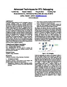
4D CAD modeling techniques is highly necessary for depiction both activities and operation. [29] 2.2. Operation base Visualization Planning Kamat and Martinez [27-29] discussed difference between 4D CAD and dynamic 3D visualization of operation simulation: virtual 3D environment depicts all facilities, resources of project and their interactions on site in addition to the construction progress and production (Figure3). In 3D visualization, the operation is visualized by linking DES to CAD models in virtual environment. 4D CAD only demonstrates the evolution of construction products and is not able to illustrate all resources and their interactions in construction site. Some other researchers [e.g. 4] tried to make integration between 4D CAD and visualization of simulated operation. For example, GPM is an approach for the modelling and simulation of construction processes based on geometric models. Geometric models are used in three ways for the design and analysis of construction process: work balance in 3D; zone generation and process decomposition. The author used DES and 4D CAD for creating 3D Chunk of construction [4]. In fact, the visualization of the simulated construction operation is so far limited to two environments; Virtual Reality and Augmented Reality environment. 2.2.1.
Visualization Planning in Virtual Reality
3D visualization of construction operation can bring valuable, complete and clear insight to project managers and other participants in all project aspects and substantially help in understanding and interpreting project process before a project starts. There are various ways to visualize the modelled construction operation in virtual environment. For example, construction Virtual Prototyping (CVP) is a tool which allows project participants to visualize project assembly in 3D environment before starting real execution. This technique is customized from DELIMA principle that is one of the most powerful virtual prototyping applications in manufacturing. CVP depicts the construability of the proposed construction approach at the commencement of real project. It was reported that this technique is more powerful in visualization than in analysing and communication [23].
Figure 3: Visualization of construction operation in virtual Reality[46]
However, there is a need for having a comprehensive and detailed visualization model by logical sequence which is able to modify, analyse and validate operation, decision and any other consequences. This kind of visualization operations requires a simulation base and able to perform a corresponding collaboration between simulation engines and visualization models. Kamat [26] presented a Dynamic Construction Visualizer (DCV) which is an engine for visualizing construction operation by tracing files during each simulation run. The simulation for this visualization technique was made by STROBOSCOPE in discrete event simulation environment. To complete animation in virtual environment, 3D CAD models in VRML formats that can be obtained from any CAD software was applied to this tool. Kamat [28] also described two criteria (verification & validation) for a credible visualization simulation. Verification is the process by which model reflects the intention of modeller accurately while validation is a criterion to determine whether the model represents real- word system accurately. The VITASCOPE is another 3D animation language by Kamat [30]. This engine is capable of visualizing construction operation in Virtual Environment by translating the outputs of discrete event simulation trace files to its language. Also CAD models and Real Time and Dates are applied to VITASCOPE application for the depiction of project resource and components. VITASCOPE integrates simulation trace files, Cad models and project schedule, and interprets them into 45 parametric statements in its language to illustrate graphical presentation of projects. Other researchers investigated the visualization of construction operation by using Simphony tool instead of STROBOSCOPE for simulation step. Al-Hussein [6] introduced a practical mythology for combining 3D visualization with special purpose simulation for tower crane operations. The system was designed in a 3D studio max environment and tested in real project construction for validity. He also used symphony.Net as a simulation tool in the design and analysis of modular construction operations. This simulation process has performed before and after the execution to foresee the outputs of each scenario and explore other scenarios. Han et al. [21] tried to make better understanding of construction process by introducing simulation, visualization and lean products. The designed system is an automated postsimulation visualization which by applying the lean principal in schedule programme gives the developed schedule. New schedule are simulated in symphony software and the outputs are extracted to an ASCII which can be used by maxscript in 3D Studio Max as inputs. Finally, production line of modular building is animated in 3D virtual environment. Although all normal visualization simulated construction systems (e.g. VITASCOPE) try to introduce perfect animations of construction operation in virtual environment, there are some issues in this kind of systems [13]: one is the modelling problems which will be discussed in next section, i.e. by developing augmented reality environment. The second problem is the interaction. All the mentioned
visualization simulated operation techniques are postprocessing animation engine that does not allow users to alter simulation process dynamically according to the outputs of the animation. Rekaplli, et al. [39] improved the process of model validation in simulated study, which is a critical step in attaining credibility. Their Discrete-Event Simulation based Virtual Reality (DES-based-VR) [39] is able to run simulation and its animation concurrently and in a manner that allow them to have interaction constantly. By monitoring real situation and problems in DES, users are able to understand subsequent choices after identifying problems in this system. These choices can improve the modelling credibility or modify the DES model. researchers designed different clock paradigms for simulation and animation by the time-advanced algorithm to achieve a concurrent simulationanimation. This system also enables Run-Time user interaction in concurrent simulation-animation by aiding extendable architecture. The third problem in VR visualization-simulation operation is the collaboration perspective. Visualization simulated operation systems do not allow people to exchange their ideas in discussion groups by contrast to the traditional paper based media, because the systems limit their presentation to the virtual screen. ARvita software enables project decision makers to wear HeadMounted-Display (HMD) and see the interaction in visual simulated construction operation on the surface of table (Figure 4) [13]. This system by integrating Augmented Reality technology and VITASCOPE system tries to use the benefits of computer visualization techniques in making the natural collaboration platform for project participants.
of construction operation. It is a powerful method for creating project activities and recourses (Figure 5). In construction domain the AR is used in a wide range of applications showing the location of columns behinds finished wall to identify subsurface utility lines and assist viewers for CAD while the most important step was the creation of ARVISCOPE. The system of Augmented Reality VISualization of Construction OPEration creates 3D AR of complex construction by using DES results. This method used the advantage of augmented reality to give better understanding of project operation in outdoor environment. Many technical challenges, such as accurate registration, automated occlusion handling, and dynamic scene construction and manipulation have been solved in this reference [7]. Augmented reality mobile operation (ARMOR) evolves from the ARVISCOPE hardware platform and by using SMART software creates AR visualization. ARMORE improved ARVISCOPE by being more accuracy, lighter weight devices, full calibration and more wearable [12].
Figure 5: Visualization of construction operation in Augmented Reality
Figure 4: Table top and screen visualization of construction operation in VR [48]
2.2.2.
Visualization Planning in Augmented Reality
The Architecture, Engineering and Construction (AEC) sector is known as one of the suitable areas for Augmented Reality application [7]. Dunston et al. [14] investigated the potential of using AR in AEC industry and found this method applicable to eight of 17 different construction domains. Amount of efforts are needed for modelling and visualizing all components of a project and its surrounding in virtual environment. The other advantage of graphical simulation in AR compared to that in VR is that the AR is able to represent realistic view for simulation. AR environment introduces the mixed views of real existing jobsite and virtual CAD model
In other efforts, the researchers in VTT Technical Research Centre of Finland represented AR4BC [42] (Augmented Reality for Building and Construction) which is a Mobile AR system for construction visualization and interaction by using mobile smart phone. This system has divided into three parts: 4D studio software for combining 3D CAD models and project schedules to give 4D CAD of construction, the final models imported in Mapstudio software and Geo-coordinate in Google Earth map and on site player with the augmented reality visualization software presenting the final visualization of construction in mobile screen (Figure.6).
Figure 6: On-site project controlling by Tablets [45]
Controlling Visualization in Construction Management For a successful construction operation, the monitoring and controlling of process should be carried out in addition to the planning. At this stage, the collection of data that represent construction status constantly is a crucial step for controlling. In fact, As-built progress should be monitored and compared with the as-planned progress continuously to obtain progress report of the project, although the maintaining of actual project execution during and according to its plan is difficult [19]. The advanced and new method of monitoring systems seems to be inevitable. Typical practices for controlling operation are manual data collection which leads to weekly or monthly reports. Project managers usually study and interpret these reports, compare them by as-planned programmes and find project deviations in real execution. A decision is then made according to these findings. The decision re-illustrating current data collection in the way such as graphs, bar charts and CPM which are time-consuming, labour-intensive, low quality, nonsystematic and visually complex systems [18]. This needs a large amount of efforts without any guarantee in result quality. Other advanced automating data collection techniques (laser scanner, RFID, bar coding, GPS, photogrammetry, Wi-Fi, UWB) are being used in different area according to their own potential and drawbacks. For instance, RFID and barcoding are powerful techniques in material and labour tracking. The photo images are more usable in reporting steps [15]. Some researchers are trying to integrate these techniques to give better outputs. For example, photogrammetry is combined with 3D laser scanner to improve the efficiency and validity of construction progress measurement [15]. El-omrai [16] combined variety of data acquisition techniques (RFID, Laser scanner, photogrammetry, bar coding etc) to generate a complete progress report of construction operation. Acquired data collected with these techniques are stored in data base for generating progress reports. In another research, Turkan [41] tried to make an automated progress tracking by using 3D laser scanner. He registered laser scan data with schedule data and 3D model to give a construction progress report. By using new algorithm, the updated schedule for construction planning is generated. The only manual step in this system is matching laser scan data with 3D model by choosing corresponding points. In another area, Golparavardfard [17] recommended photography techniques for collecting data rather than other advanced techniques due to the minimum cost and no training needed. He tried to automate the visualization of construction progress monitoring by comparing 3D model of as-planned with the real photos of the same perspectives (camera view matching). Through a material-based-image retrieval approach, the progress statuses of real execution are measured and colour coded. On the basis of the deviations detected, the progress performance by Earned Value Analysis is quantified. By superimposing the 4D as-planned and time-
lapse photography which represents actual progress in augmented reality environment, clear comparisons are provided and progress status of project is colour-coded. Golparvarfard et al. [19] also presented 4DAR by integrating augmented reality and structure from motion techniques. (Figure7).
Figure7: 3D reconstruction of as-built project by 2D photos (Structure of Motion Techniques) [44]
Reconstruction of 3D cloud point of actual projects by unordered photos is presented in order to compare the as-built situation at construction site against 4D CAD models of plans. The main abilities and potential of this method can be summarised including low cost data collection and processing, high level of accuracy and no need for training for operation. However, laser scanning cloud point has a better application in some criteria such as automation and accuracy with comparison to photography 3D reconstruction [20].
Conclusions and Future Works Although each project has its unique procedure and operation, there are some projects consisting of a large amount of repetitive activities during a project life cycle. Visualization techniques are powerful managing tools in a wide range area of construction. The projects with repetitive activities like onsite MMC have potentials to be planned and controlled by these techniques. Conflicts and other important factors in execution can be understood at pre-construction phase by visualization and simulation methods. Project operations can be planed according to the intention. During the construction process, participants are able to solve any problems which occur during execution by investigating possible scenario and available options. Therefore, using this kind of techniques is highly required in managing MMC. However, a large amount of advancements attained in the area of visualized construction management; there is still the lack of using applicable and efficient visualization management system in construction industry. In one hand, using visualization techniques in both the planning and controlling stages of construction operation should be performed together simultaneously for an optimised outputs. On the other hand, the system should also be able to modify itself constantly according to its feedback. By designing a system with these attributes, the advantages of visualization techniques can be fully realised and the system can be used as the most powerful tool for a comprehensive construction management.
REFERENCES [1] AbouRizk, S. (2010). “The role of simulation in construction engineering and management.” J. Constr. Eng. Manage. [2] AbouRizk, S., Halpin, D., Mohamed, Y. (2011). “Research in Modeling and Simulation for Improving Construction Engineering Operations.” J. Constr. Eng. Manage. [3] AbouRizk, S., Mohamed, Y. (2000). “SIMPHONY .An Integrated Environment for Construction Simulation.” Proc., 2000 Winter Simulation Conf. [4] Akbas, R. (2003). “Geometry based modeling and simulation of constructionprocesses.” Ph.D. thesis, Dept. of Civil and Environmental Engineering,Stanford Univ., Palo Alto, CA. [5] Akinci, B., and Fischer,M. (2000). “An automated approach for accountingfor spaces required by construction activities.” in Proc., 6th Construction Congress, ASCE, Reston, VA. [6] Al-Hussein, M., Niaz, M.A., Haitao, Y., Kim, H. (2005). “ Integrating 3D visualization and simulation for tower crane operations on construction site.” Automation in Construction 15, ELSEVIER, pp. 554–562. [7] Behzadan, A. H. (2008). “ARVISCOPE: Georeferenced Visualization of Dynamic Construction Processes in Three-Dimensional Outdoor Augmented Reality.” Ph.D. thesis, Dept. of Civil and Environmental Engineering, University of Michigan, Ann Arbor, MI. [8] Burwood, S., Jess, P. (2005). “Modern Method of Construction Evaluation or Revelution?. ” A BURA Steering and Development Forum Report.http://www.buildicf.co.uk/pdfs/... [9] Cartwright, P., Moulinier, E., Novakovic, O. and Fletcher, K. SmartLIFE: Lessons learned. BR 500. Bracknell, HIS BRE Press. (BRE TRUST REVIEW 2010.) [10] Chau, k.w., Anson, M., Zhang , J.P. (2004). “Four-Dimensional Visualization of Construction Scheduling and Site Utilization.” ASCE Journal of Construction Engineering and Management. [11] Chin, S., Yoon, S., Choi , Ch., Cho, Ch. (2008). “RFID+4D CAD for Progress Management of Structural Steel Works in High-Rise Buildings.” JOURNAL OF COMPUTING IN CIVIL ENGINEERING. [12] Dong, S., and Kamat, V. R. (2010). “Robust mobile computing framework for visualization of simulated processes in augmented reality.” Proc., 2010 Winter Simulation Conf., IEEE, Piscataway, NJ. [13] Dong, S., and Kamat, V. R. (2011). “Collaborative visualization of simulated processes using tabletop fiducial augmented reality.” Proceedings of the 2011 Winter Simulation Conference. [14] Dunston, P., Wang, X., Billinghusrt, M. and B. Hampson, B.(2002). Mixed Reality benefits for design perception. In Proceedings of 19th International Symposium on Automation and Robotics Construction (ISARC 2002),191-196, Gaithersburg, MD: NIST. [15] El-Omari, S., Moselhi,O. (2008). “Integrating 3D laser scanning and photogrammetry for progress measurement of construction work. ” Automation in Construction 18. [16] El-Omari, S., Moselhi,O. (2011). “ Integrating automated data acquisition technologies for progress reporting of construction projects. ” Autom Constr 2011 10;20(6):699-705. [17] Golparvar-Fard, M., Peña-Mora, F., Arboleda, C. A.(2006) “SEMIAUTOMATED VISUALIZATION OF CONSTRUCTION PROGRESS MONITORING.” www.manigolparvar.com/.../CRC2007_GolparvarFardPena-Mora.pdf [18] Golparvar-Fard, M., Peña-Mora, F., Arboleda, C. A., and Lee, S. H. (2009a). “Visualization of construction progress monitoring with 4D simulation model overlaid on time-lapsed photographs.” J. Comput. Civ. Eng., 23(6), 391–404. [19] Golparvar-Fard, M., Peña-Mora, F., and Savarese, S. (2009b). “D4AR—A4-dimensional augmented reality model for automating construction progress data collection, processing and communication.” J. Inf. Technol. Constr., 14, 129–153. [20] Golparvar-Fard, M., Bohn, J., Teizer, J., Savarese, S., Peña-Mora F. (2011). “Evaluation of image-based modeling and laser scanning accuracy for emerging automated performance monitoring techniques. ” Autom Constr 2011 12;20(8):1143-1155. [21] Han, S.H., Al-Hussein, M., Al-Jibouri, S. (2012). “Automated postsimulation visualization of modular building production assembly line.” Autom Constr 21(0):229-36.
[22] Hartmann, T., Gao, J., Fischer, M. (2008). “Areas of application for 3D and 4D models on construction projects. ” ASCE Journal of Construction Engineering and Management 134 (10) (2008) 776–785. [23] Huang,T., Kong, C.W., Guo, H.L., Baldwin, A., Li, H. (2007). “A virtual prototyping system for simulating construction processes.” Autom Constr 16(5):576-85. [24] Jongeling, R., and Olofsson, T. (2007). “A method for planning of work-flow by combined use of location-based scheduling and 4D CAD.” Autom. Constr., 16(2), 189–198. [25] Jongeling, R., Kim, J., Fischer, M., Mourgues, C., and Olofsson, T. (2008).“Quantitative analysis of workflow, temporary structure usage, and productivity using 4D models.” Autom. Constr., 17(6), 780–791. [26] Kamat, V. R., and Martinez, J. C. (2000). “3D VISUALIZATION OF SIMULATED CONSTRUCTION OPERATIONS.” Proceedings of the 2000 Winter Simulation Conference. [27] Kamat, V. R., and Martinez, J. C. (2002). “Comparison of simulationdriven construction operations visualization and 4D CAD.” Proceedings of the 2002 Winter Simulation Conference., IEEE, Piscataway, NJ, 1765–1770. [28] Kamat, V. R., and Martinez, J. C. (2003). “Validating Complex Construction Simulation Models Using 3D Visualization.” http://dx.doi.org/10.1080/02329290290028507. [29]Kamat VR, Martinez JC, Fischer M, Golparvar-Fard M, Pea-Mora F, Savarese S.(2011). “Research in visualization techniques for field construction. ” J Constr Eng Manage 2011;137(10):853-862. [30] Kamat, V. R. (2003). “VITASCOPE: Extensible and scalable 3D visualization of simulated construction operations.” Ph.D. dissertation, Dept. of Civil and Environmental Engineering, Virginia Tech, Blacksburg,VA. [31] Kang, J.H., Anderson, S.D., Clayton , M.J. (2007). “Empirical Study on the Merit of Web-Based 4D Visualization in Collaborative Construction Planning and Scheduling.” Autom Constr 18(2):219-36. J. Constr. Eng. Manage. [32] Kataoka, M. (2008). “Automated Generation of Construction Plans from Primitive Geometries.” Autom. Constr. [33] Ma, Z., Shen, Q., Zhang , J. (2005). “Application of 4D for dynamic site layout and management of construction projects.” Autom. Constr., 14(3):369-81. [34] Mahalingam, A., Kashyap, R., Mahajan, C. (2010). “An evaluation of the applicability of 4D CAD on construction projects.” Autom Constr 19(2):148-59. [35]Martinez, J. C. (1996). “STROBOSCOPE: State and resource based simulation of construction processes.” Ph.D. dissertation, Univ. of Michigan, Ann Arbor, MI. [36] McKinney, K., Kim, J., Fischer , M., Howard, C. (1995). “Interactive 4D-CAD.” www.stanford.edu/group/4D/workspace/papers/asce-96.pdf. [37] Modern Methods of Housing Building. Parliamentary Office of Science and Technology, Postnote, December 2003, Number 209. [38] Pan, W., Gibb, A.G.F, Dainty, A.R.J. (2008). “Leading UK housebuilders’ utilisation of offsite modern methods of construction. ” Building Research & Information, 36(1), pp. 5667http://dx.doi.org/10.1080/09613210701204013. [39] Rekaplli, P.V., Gao, J., Martinez, J. C. (2011).“Discrete-Event Simulation-Based Virtual Reality Environments for Construction Operations: Technology Introduction. ” ASCE Journal of Construction Engineering and Management. [40] Russell, A., Staub-French, S., Tran , N., Wong, W. (2009). “Visualizing high-rise building construction strategies using linear scheduling and 4D CAD.” Autom. Constr., 18(2):219-36. [41] Turkan, Y., Bosche, F., Haas, CT., Haas R.(2012) “Automated progress tracking using 4D schedule and 3D sensing technologies“. Autom Constr 3;22(0):414-421. [42] Woodward, Ch., and Hakkarainen, M. (2010). “Mobile Augmented Reality System for Construction Site Visualization.” VTT Technical Research Centre of Finland, www.navteq.com/woodwardhakkarainenismar2011-workshop-fin. [43] http://www.mesaimalat.com/en/ertf-modular-tunnel-form-system) [44] http://www.sciencedirect.com/science/article/pii/S1524070311000658 [45] http://www.sketchupdate.blogspot.co.uk/2011_12_01_archive.html [46] http://www.solutions-inc.co.uk/index.php/autocad) [47] http://www.synchroltd.com/news/NA-20101020152531 [48] http://www.vr.ucl.ac.uk/projects/arthur.