Agent-Based Modelling and Simulation of Distributed Business Processes in Supply Networks Nick Szirbik, Gerd Wagner, Florin Tulba Corresponding email:
[email protected] Eindhoven University of Technology (TU/e) – Faculty of Technology Management, I&T P.O. Box 513 – 5600 MB Eindhoven – The Netherlands
Abstract: Conceptual modelling, simulation and software development taken together, as a cyclical process, can be seen as a natural way to implement information systems. However, there is a gap between the tools used for each of these steps. In this paper, we propose a methodology to link the conceptual modelling and the simulation techniques, by using the same language, AORml. We show a specific simulator structure (adapted to fit with the features of the language), and how the language constructs can be unambiguously translated into execution models usable for simulation and further development of agentoriented software. Keywords: agents, simulation, intra and interorganisational business processes, supply networks
1 Introduction Agent-based simulation is a novel paradigm, which is particularly attractive for simulating business processes. In this paper we discuss a combination of an agent-based
SysTF: S,e
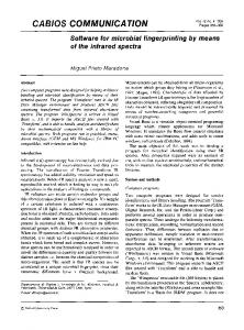
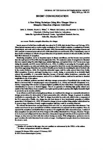
simulation architecture with an agent-oriented modelling language (acronym: AORml) that allows to specify executable simulation models in a high-level UML-like graphical fashion. Agent-Based Discrete Event Simulation (ABDES) is an extension of Discrete Event Simulation (DES). The conceptual difference is related to the “distributed” state of the system. Since the system is composed of distributed entities, i.e. agents, its state consists of the combination of all entity states superimposed on an “environment” state (see Figure 1). DES is a very generally applicable and powerful approach in many empirical domains, in particular those involving technical and social organisations. The simulation model of these organisations can be viewed as a discrete model of dynamic systems. There are two operational models for DES systems. In an event-driven DES, the simulated time is advanced according to the occurrence time of the next event. In a time-driven DES, the simulated time is advanced in regular time steps.
S'
e S
System 1
*
*
SysTF
Event OccurenceTime
SystemState S' Time * *
*
EntityState
Entity 1
*
Time
Figure 1: The basic model of discrete event simulation as a UML class diagram. As a system consists of a number of entities, its state consists of all the states of these entities. A system transition function SysTF takes the current system state S and a statechanging event e, and determines the resulting successor state S’.
- provide mechanisms that allow the experimentator to intervene in the simulation events. As most the authors note, in particular the last two of these requirements are not satisfied by the available platforms (see Davies, 2002, and Repenning, 2000). These two requirements demand some kind of support for interactive simulation. However, interactivity is not treated as a fundamental concept in (Marietto et al, 2002), (Kinshuk et al, 1998), or (Perumalla and Fujimoto, 1999). Platforms for Agent-Based Simulation are Swarm (Johnson and Lancaster, 2000, Minar et al, 1996), SDML (Moss et al, 1998), Sesam (Klügl 2001, and Klügl 2002), MadKit (Ferber et al, 2000) and CORMAS (CIRAD, 2001, and Le Page et al, 2000). A particularly interesting class of simulation systems is formed by international technology competitions such as RoboCup (Noda et al, 1998, and Chen et al, 2002) and Trading Agent Competition (TAC) (SICS 2002). Both RoboCup and TAC can be classified as Interactive Agent-Based Realtime Simulation Systems. Our paper is structured as follows: section 2 introduces the basic notions of ABDES, section 3 deals with some of the features of the simulator, section 4 provides an illustration of a specific scenario in supply networks and section 5 concludes the paper.
In a more general sense, Agent-Based Simulation is being used in various research areas, today. In particular, it is being used in: - Biology, e.g. for investigating eco-systems or in population ethology (especially with respect to ants and other insects), see, e.g., (Klügl, 2001); - Bioinformatics, e.g. in gene expression analysis (Schober, 2002); - Engineering: for analyzing and designing complex (socio-) technical systems, such as Automatically Guided Vehicle Transport Systems; - Economics: e.g. in the simulation of auctions and markets, see Trading Agent Competition (SICS, 2002); - Social Sciences: e.g. in (Conte and Dignum, 2001), (Davidsson, 2002) the phenomena of social monitoring and norm-based social influence and in (Hales, 2002) the cooperation in teams is studied. In (Marietto et al, 2002) requirements for Agent-Based Simulation platforms are presented. They are to - allow controlled simulations with repeatable events; - allow asynchronous message exchange between agents; - make in addition to external events (like messages) also internal/cognitive events observable; - be able to integrate different environments with the simulation (no matter if they are controlled by the simulator or not); S ysTF: S ,e S'
e
O ccurence tim e
S ystem S tate S '
S ystem 1
*
Tim e
*
1 Ac tionE vent
*
N on ActionE vent
*
*
M essage
Tim eE vent
E ntityS tate
E ntity 0..1
E vent
S ysTF
S
1
*
Tim e
*
*
N onC om m ActE vt
sends 1
*
1 O bject
1
receives
Ag ent creates
1
{xor}
* E ntityB elief
P ercept * *
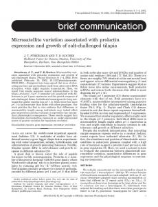
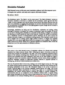
Figure 2: Agent-based discrete event simulation. Agents maintain beliefs about entities and process precepts referring to events. Notice that in this model communication (an agent sends/receives messages) is separated from perception (an agent perceives non-communicative action events and nonaction events).
2 From DES to ABDES For extending and refining the basic DES model into an agent-based DES model, we start with a time-driven DES (since we need small regular time steps for simulating the perception-reaction cycle of agents) and we make a number of essential ontological distinctions (Ferber and Gutnecht, 1998): !
The enduring entities of a system (also called endurants in foundational ontrologies) are distinguished into agents and (passive) objects (Booth, 1999).
!
Agents maintain beliefs (referring to the state of their environment) and process percepts (referring to events), see (Dennet, 1971).
!
Events can be either action events or nonaction events (see HLA, 2002).
!
Action events can be either communicative (messages) or non-communicative.
Finally, the simulation system needs to be partitioned into 1.
the environment simulator responsible for managing the state of all external (or physical) objects and for the external/physical state of each agent;
2.
a number of agent simulators responsible for managing the internal (or mental) state of agents.
Figure 2 shows the resulting ABDES extension of the basic DES model. The advantages of the ABDES approach are the following !
Supports structure-preserving modelling and closer-to-reality simulation: −
Passive entities with certain properties are modelled as objects with corresponding attributes.
−
Actors (active entities) are modelled as agents, which have beliefs and perceptions , and interact with each other and with their environment.
!
Supports simulation.
!
Supports interactive simulation.
functionally
distributed
Allows to model pro-active behaviour, in addition to the basic reactive behaviour. ABDES defines an abstract architecture for simulation systems, which can be instantiated by different concrete architectures and systems. According to our ontological distinction between agents and objects, only
agents can perceive events, perform actions, communicate, or make commitments. Ordinary objects are passive entities with no such capacities. This contrasts with the language used in the literature on object-oriented programming, where objects `communicate' or `interact' with each other by sending `messages'. We argue that the UML term `collaboration' between objects corresponds only to a very low-level sense of communication and interaction. In fact, sending a `message' in the sense of OO programming corresponds rather to a (possibly remote) procedure call, and not to a communication act (or speech act): while an OO message has no generic structure at all, a speech act message has the mandatory form m(c) where m is the message type (expressing the so called `illocutionary force'), and c is the message content (composed of propositions and/or action terms). Conceptually, we consider that it is not justified to model in a supply network the customers and suppliers as `business objects' in the same way as bank accounts and software artefacts (such as GUI push buttons). Mere object-orientation does not capture communication and interaction in the highlevel sense of business processes carried out by business actors. This view is shared by (Jacobson, 1994) who remarks (see p.36) that ``it is bizarre to apply the way of thinking that governs computer systems to business processes''.
3 Modelling and Simulating Agent-to-Agent Communication We use the Agent-Object-Relationship modelling language (AORml), see (Wagner, 2003), for specifying simulation models. The AOR modelling approach is based on an ontological distinction between active and passive entities, that is, between agents and objects. The agent metaphor subsumes both artificial and natural agents (humans and organisations). This way, the users of the information system are included and also considered as agents in AOR modelling. AOR distinguishes between agents and objects according to these two main points: 1) while the state of an object in OO programming has no generic structure, the state of an agent has a ‘mentalistic’ structure: it consists of mental components such as beliefs and commitments. 2) while messages in object-oriented programming are coded in an application-specific ad-hoc manner, a message in Agent-Oriented Programming is coded as a
‘speech act’ according to a standard agent communication language that is applicationindependent (Edmonds and Wallis 2002). In AORml, an entity is an agent, an event, an action, a claim, a commitment, or an ordinary object. Agent and object form, respectively, the active and passive entities, while actions and events are the dynamic entities of the system model. Commitments and claims establish a special type of relationship between agents. These concepts are fundamental components of social interaction processes and can explicitly help to achieve coherent behaviour when these processes are semi or fully automated.
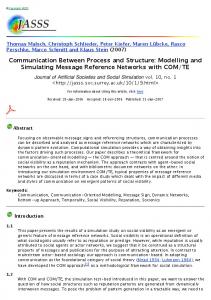
Only agents can communicate, perceive, act, make commitments and satisfy claims. Ordinary objects are passive entities with no such capabilities. Besides human and artificial agents, AOR also models institutional agents. Institutional agents are usually composed of a number of human, artificial, or other institutional agents that act on its behalf. Organizations, such as companies, government institutions and universities are modelled as institutional agents, allowing modelling the rights and duties of their internal agents. Figure 3 shows the elements of an AOR external model, in which the language notation can be seen.
Figure 3: The core elements of AOR external models. Object types belong to one or several agents (or agent types). They define containers for beliefs. If an object type belongs exclusively to one agent or agent type, the corresponding rectangle is drawn inside this agent (type) rectangle. If an object type represents beliefs that are shared among two or more agents (or agent types), the object type rectangle is connected with the respective agent (type) rectangles by means of an UML aggregation connector. As it can be seen in Figure 3, there is a distinction between a communicative action event (or a message) and a noncommunicative action event. Also, AOR distinguishes between action event and nonaction event types. The figure also shows that a commitment/claim is usually followed by the action event that fulfils that commitment (or satisfy that claim). The simulation system consists of an environment simulator and of a number of agent simulators, one for each
participating agent. The state of the simulation system consists of: - the simulated time t - the environment state representing o the environment (as a collection of passive objects) and o the external states of all agents (e.g., their physical state, their geographic position, etc.) - the internal agent states (representing their perceptions, beliefs, memory, goals, etc.). - a (possibly empty) list of future events A simulation cycle consists of the following steps: 1. At the beginning of a new simulation cycle, say at simulated time t, the environment simulator determines the current events comprising
a) all the events of the future events list whose occurrence time is now
small planes, like the twin-piston engine, upto-2250kg class of airplanes.
b) exogenous events whose occurrence time is now (e.g. stochastic non-action events or events created by actors that do not belong to the simulated system)
In our example we consider that the Thunder Avia airplane can be separated in three main parts – from a logistic point of view: the fuselage, the engine and the avionics (special electronics for navigation, identification and communication). The Avia enterprise is specialized in producing the fuselage and in assembling the final product. The name of the fuselage (as a product) its Thunder_Fuselage.
2. The environment simulator computes, on the basis of the current environment state and the current events, a) a new environment state, b) a set of successor events to be added to the future events list at different moments (representing events physically caused by the current events), c) for each agent, its perceptions 3. Each agent simulator computes, on the basis of the current internal agent state and its current perceptions, a) the new internal agent state, b) a set of action events representing the actions performed by this agent after a corresponding delay τi (which can be added to the future events list with time stamps t+τi) 4. The future events list is updated by removing all the processed events and adding the computed action and successor events Modelling and Simulating Agent-toAgent Communication 5. The environment simulator sets the simulated time t to the next attached time stamp to be found in the future events list and starts over with step 1 of the simulation cycle.
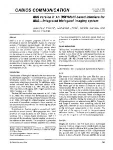
The Thunder plane has two engines. The engines are manufactured by two supplier enterprises: Lycoming and Walter. Of course these suppliers manufacture many types of engines. For Thunder, the type is for 450 HP (horse power). We assume that the names (or logistic codes) of the engines for Thunder are Lycoming 450 and Walter 450. A Thunder plane must have both engines of the same type. The avionics package (displays, electronic controls, on-board computers, radios, radars and navigations systems) can be delivered either by Thales, either by Collins. Thunder is compatible with a package that has the logistic code CS2000. The products name-codes are: Thales CS2000 and Collins CS2000 Thus, we have the following supply chain (modelled via an AOR structure diagram) as depicted in figure 5, based on the class AOR diagram of the generic supply chains. This is presented in figure 4 – where the association class Purchase/Sale links enterprises via class Item, representing product types. We consider for the simplicity that an item is a unique product type, though in reality we have product families with parameters.
4 An example Purchase/Sale
The airplane is assembled by a specific enterprise, in our modelling an institutional agent, which plays the role of the final integrator. The enterprise – agent – name is: “Avia”). In following scenarios, we can have more final integrators of a virtual family of
-Cus to m e r *
*
-S u ppli er *
To validate our conceptual model for agent-based simulation we investigated first a very simple supply chain case, involving only five nodes (enterprises). The final product is a small airplane (Product type name: “Thunder”). There is only one type of this product in the scenario, with only some minor variations, depending on the type of engine and avionics. In a more elaborate scenario, we can have more types of the final product.
Item
Enterprise
Figure 4. A generic description of a supply chain in an AOR class diagram
Lycoming: Enterprise supplier
Walter: Enterprise
450HP: Item
supplier CustomerX: Enterprise consumer consumer Avia: Enterprise
supplier
consumer
Thunder: Item
Collins: Enterprise supplier
CS2000: Item Thales: Enterprise supplier
Figure 5. The instance-level model of the example Supply Chain In figure 5, the links for “Purchase/Sale” have no instances for the association classes, because we consider this diagram only a snapshot of the evolution of the network. This diagram captures the state before the purchasing scenario begins. The final state is presented in figure 7. The Simplified Bill of Materials (BOM) is the following: - Thunder (made by Avia) - Fuselage_Thunder (made by Avia) - engine 450 x 2 (made by Lycoming OR Walters, both engines for a plane should be the same) - avionics CS2000 (made by Thales OR Collins) What the agents (Avia, Lycoming, Walter, Collins and Thales) know – can be expressed as First Predicate Order Logic (FPOL) facts: For agent 1 “Avia”: salesItems( [thunderPlane]), manufacturedItems( [ [planeFuselage, 300000, 40], [planeAssembly, 150000, 30], [thunderPlane, 0, 0] % after assembly, the plane is finalized already ]), producersOf( [ [engine450, [lycoming, walter]],
[avionicsCS2000, [collins, thales]] ]) These beliefs are about the knowledge the final integrator has about the products he manipulates, some of them are being purchased from the suppliers. To illustrate the Bill-of-Material relations, we are using facts with the predicate name “bom”, representing the arcs in the BOM graph (figure...). bom( planeFuselage, [[planeFuselage, 1]]), bom( planeAssembly, [[planeAssembly, 1]]), bom( thunderPlane, [ [planeFuselage, 1], [engine450, 2], [avionicsCS2000, 1], [planeAssembly, 1], [thunderPlane, 1] ]) The purchasing process is starting in the following way: the customer sends a message of type “request for quotation” to agent Avia. In Prolog, this can be represented by the metapredicate: sM( avia, rfq( Ref, thunder, Quantity, ReqDelDate, ReqTimeout)). In the agent simulator, this should be an explicit message received by agent Avia. Agent Avia infers the externally sourced requirements (engines and avionics) by doing a simple BOM explosion (multiplies the number
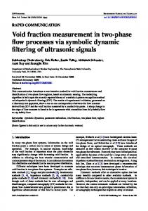
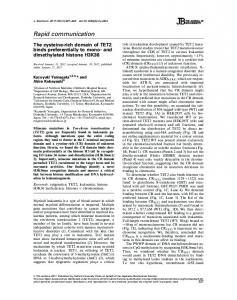
by 2 for the engines), and sends a RFQ message to agents Lycoming, Walter, Collins and Thales. sM( lycoming, rfq( Ref, engine450, Quantity, ReqDelDate,ReqTimeout)). sM( walter, rfq( Ref, engine450, Quantity, ReqDelDate, ReqTimeout)). sM( collins, rfq( Ref, avionicsCS2000, Quantity, ReqDelDate, ReqTimeout)). sM( thales, rfq( Ref, avionicsCS2000, Quantity, ReqDelDate, ReqTimeout)). The four supplier agents may respond with the following messages: sM( [avia], quotation( Ref, TotPrice, PromisedDelDate, CommitedUntilDate)) or sM( [avia], rejectRfq( Ref)) If Avia cannot obtain a certain component, it will forward the rejectRfq to the customer. Otherwise it will select a supplier for avionics and other for the engines. It will send a message to all. For example: sM( [SupplyingAgent], order( Ref, CommitedUntilDate)) Then the corresponding suppliers have to confirm they commit to deliver: sM( [avia], confirmOrder( Ref)) If everything is going well, agent Avia will make the delivery for the referred order: doAction( deliver( customer, Ref)) Showing the scenario by following the simulation execution is tedious and difficult to follow. This scenario can be presented in better way (clearer/graphic, more comprehensive and also in more detail) by using an AOR sequence diagram (figure 6). This diagram can be red in the following way: Step 1. CustomerX sends Request for quotation to the final integrator Avia Step 2. Avia sends two RFQs to all suppliers (substep 2.1 for engine, 2.2 for avionics – these two can take place in any order or in parallel)
Step 3. In any order (or in parallel), Avia receives quotations/rejections from the suppliers (note that sub-step 3.4 is a “reject”) Step 4. Based on acquired data, Avia selects the preferred suppliers in this instance and makes a quotation to CustomerX. Step 5. CustomerX issues a firm order. Step 6. Avia issues firm orders to the preferred suppliers (in any order) Step 7. The preferred suppliers (Lycoming and Thales in this instance) confirm these orders. This will create claim/commitments beliefs in Avia and the suppliers (indicated by the arrow). Step 8. Avia confirms the order of CustomerX and a claim/commitment is created. Step 9. The engine (9.2) and the avionics (9.1) are delivered to Avia. Step 10. The final plane is delivered to CustomerX. After step 8, we can represent the state of the network using a structural AOR diagram at instance level (as in figure 5). In figure 6 there are two kinds of communicative action/events (messages): point-to-point and broadcasted. Figure 8 shows how generic Claim/Commitment objects became in this specific scenario, objects of class Purchase/Sale. We can also represent a more generic view about these kinds of scenarios by using interaction diagrams, which are at a class level. For our supply chain scenario, such a diagram looks like in figure 8 To have more insight in the scenario description, we can use AOR interaction pattern diagrams, which link rules from the behavioural description to a graphical representation. The advantage of these kinds of diagrams is that they are semantically unambiguous and they can be translated directly (even automatically) into the simulation code. For the simulation, we have used first the JESS (Java based CLIPS) inference engine, but this has the disadvantage that it provides only forward chaining inference over the rules. Another variant, based on backward chaining, was written in Prolog. In both cases, the simulator shell and the rule bases have been separated. A generic inference engine is provided for the environment and for the agents. The agents have each a “copy” of the inference engine running, providing in this way for the simulated “autonomy” of the agents.
DeliverItem reference
9.2
Lycoming
DeliverItem
7.1
ConfirmOrder reference Order reference
6.2
thunder : Item
CustomerX
RFQ reference quantity reqDelDate
1
3.1
Avia
engine450 : Item
Quotation reference price promisedDelDate
4
RFQ reference quantity reqDelDate
5
Order reference
Quotation reference price promisedDelDate
2.1
W alter
3.4
RejectRFQ reference Quotation reference price promisedDelDate
3.2 ConfirmOrder reference
8
RFQ reference quantity reqDelDate
DeliverItem
10
DeliverItem reference
Collins
2.2
avionicsCS2000 : Item Quotation reference price promisedDelDate
3.3
Thales
6.1
Order reference
ConfirmOrder reference
7.2
DeliverItem
DeliverItem reference
9.1
Figure 6. AOR interaction sequence diagram presenting the purchase scenario Contract-LA: Purchase/Sale Contract-ACX: Purchase/Sale quantity: price: delivery date:
S upp
lie r
su
m
er
er um
n Co
t
Avia: Enterprise uc
er
od
um
ns Co
450HP: Item
ns
Pr
od
Co
Pr
Lycoming: Enterprise
Su
pp
uc
t
lie
r
quantity: price: delivery date:
CustomerX: Enterprise
Thunder: Item
Thales: Enterprise
Sup plie r
P ro
du
ct
Contract-TA: Purchase/Sale
CS2000: Item
quantity: price: delivery date:
Figure 7. The second snapshot of the network status (after all the orders are confirmed)
Enterprise
EndCustomer
FinalIntegrator RFQ reference quantity reqDelDate
FirstTierSupplier RFQ reference quantity reqDelDate
RejectRFQ reference
RejectRFQ reference
Quotation reference price promisedDelDate
Quotation reference price promisedDelDate
Item
Item
Order reference
Order reference ConfirmOrder reference
ConfirmOrder reference
DeliverItem
DeliverItem
DeliverItem reference
DeliverItem reference
Figure 8. An generic interaction diagram, showing the main entities and relations in purchasing scenarios The use of a backward chaining inference engine brings the possibility to define goals, deductive rules and generally a “pro-active” and planning behaviour of the agent. With only a forward chaining mechanism, the agents will be purely reactive. We are currently working to integrate both machines, using the Mandarax(tm) rule-base system, which has also the advantage of being built completely in Java, allowing easier integration and testing of code, comparatively with the JESS and Prolog development environments.
5 Conclusions We have presented a general approach to modelling and simulating communication between agents, and a discussion of an example scenario, the quotation and order placement process in the aircraft industry. Our simulator is still in an early prototype stage, so we could not yet run scenarios that are both reactive and goal oriented. The most important achievement of this modelling and simulation technique is that is using the same graphical language (AORml) for both he conceptual modelling of the domain of the simulation and for the simulation model. Moreover, via simulation we can develop (implement) agent based information systems for supply networks and other business organisations, by using the UML-like features of the AORml, which are suited for software development. More about the AORml supported software development
methodology of the agent-based information systems for supply networks can be found in (Szirbik et al, 2002). References Booth, G., 1999: CourseWare Programmer's Guide, Yale Institute for Biospheric Studies, see at http://www.gingerbooth.com/courseware/pa ges/manual.pdf Le Page C., Bousquet F., Bakam I.,. Bah A, Baron C., 2000, CORMAS: A multiagent simulation toolkit to model natural and social dynamics at multiple scales, at the Workshop "The ecology of scales", Wageningen (Netherlands), 2000, see at http://cormas.cirad.fr/pdf/cormasw.pdf CIRAD, 2001, CORMAS, Common-pool Resources and Multi-Agents Systems, User's Guide, see at http://cormas.cirad.fr/pdf/userguide.pdf Conte R. and Dignum F, 2001, From Social Monitoring to Normative Influence, Journal of Artificial Societies and Social Simulation vol. 4, no. 2, 2001. Davidsson P., 2002, Agent Based Social Simulation: A Computer Science View Journal of Artificial Societies and Social Simulation, Vol. 5(1), 2002. Davies A., 2002, EcoSim: An Interactive Simulation, Workshop at Duquesne University, Pittsburgh, 2002, see at http://ecedweb.unomaha.edu/ecosim.htm
Dennett D.C., 1971, Intentional Systems, The Journal of Philosophy, 68, 1971. Edmonds B.,. Wallis S, 2002, Towards an Ideal Social Simulation Language, Manchester Metropolitan University, see at ftp://cfpm.org/pub/papers/taissl.pdf. Ferber J., Gutknecht O., 1998, A meta-model for the analysis and design of organizations in multi-agent systems. Proceedings of the Third International Conference on MultiAgent Systems (ICMAS´98), IEEE Computer Society Press, pp128-135, also at: http://www.cs.toronto.edu/~mkolp/lis2103/ic mas98.pdf Hales D., 2002, Evolving Specialisation, Altruism and Group-Level Optimisation Using Tags, MABS'02 workshop at the AAMAS 2002 Conference, Springer-Verlag, see at: http://cfpm.org/~david/papers/mabs3.ps HLA- a High Level Architecture, 2002, Defence Modelling and Simulation Office, see at: https://www.dmso.mil/public/transition/hla/i ndex_html Jacobson I., 1994, The Object Advantage, Addison-Wesley, Wokingham (England), Klügl F., 2001, Multiagentensimulation, Addison-Wesley Verlag. Kinshuk, R. Oppermann, R. Rashev, H. Simm, 1998, Interactive Simulation Based Tutoring System with Intelligent Assistance for Medical Education, Proceedings of EDMEDIA / ED-TELECOM 98, AACE, VA, pp715-720, see at: http://fimswww.massey.ac.nz/~kinshuk/papers/edmedi a98.html Ferber J., Gutknecht O., Michel F, 2002, MadKit Development Guide, see at: http://www.madkit.org/madkit/doc/devguide /devguide.html Marietto M., David N., Sichman J., Coelho H. , 2002, Requirements Analysis of MultiAgent-Based Simulation Platforms: State of the Art and New Prospects, University Sao Paulo, see at: http://www.pcs.usp.br/~jaime/papers/mariett o_mabs02_e.ps Moss S., Gaylard H., Wallis S., Edmonds B., 1998, SDML: A Multi-Agent Language for Organizational Modelling, Computational and Mathematical Organization Theory 4, (1), 43-70. Perumalla K., Fujimoto R. , 1999, Interactive parallel simulations with the Jane
Framework, Georgia Institute of Technology, see at: http://www.cc.gatech.edu/computing/pads/P APERS/jane-websim99.pdf Repenning A., 2000, AgentSheets: an Interactive Simulation Environment with End-User Programmable Agents, Universität Colorado, see at: http://www.cs.colorado.edu/~ralex/papers/P DF/Interaction2000.pdf Noda I., Matsubara H., Hiraki K., Frank I., 1998, Soccer Server: a tool for research on multi-agent systems, Applied Artificial Intelligence, 12, 2-3. Chen M., Foroughi E., Heintz F., Huang Z., Kapetanakis S., Kostiadis K., Kummeneje J., Noda I., Obst O., Riley P., Steffens T., Wang Y., Yin X., 2002, User Manual, RoboCup Soccer Server, see at: http://telia.dl.sourceforge.net/sourceforge/sse rver/manual.pdf Schober D., 2002: Microarrays, Genexpressionsanalyse und Bioinformatik, BioSpectrum, Special, 3/2002, S. 307. Klügl F., 2002, Introductory slides to SeSAm, see at: http://www.simsesam.de http://ki.informatik.uniwuerzburg.de/~sesam/tutorials/shortIntroduc tion/ Minar N., Burkhart R., Langton C., Askenazi M., 1996, The Swarm Simulation System: A Toolkit For Building Multi-Agent Simulations, se at: www.swarm.org/archive/overview.ps Johnson P., Lancaster A., 2000, Swarm User Guide,. see at: http://www.santafe.edu/projects/swarm/swar mdocs/userbook/userbook.html SICS: Trading Agent Competition 2002, see at: http://www.sics.se/tac/ Szirbik N., Wagner G., La Poutré H., 2002, “A Generic Framework for Simulation of Supply Networks with Bargaining Agents”, in “Collaborative Trends in Manufacturing Systems” (Eds. H-J. Pels, J.C. Wortmann, and H.S. Jagdev), selected papers of the APMS Conference, Eindhoven, September 2002, pp339-352, , Kluwer Academic Publishers. Wagner G., 2003 The Agent-ObjectRelationship Meta-Model: Towards a Unified Conceptual View of State and Behaviour, Information Systems 28:5 (2003), 475 - 504.