telecommunications network surveillance and fault management. ... correlation applications, and for real-time alarm .... the application development process.
Alam Correlation Correlating multiple network alarms improves telecommunications network surveillance and fault management. .......m..m
Gabriel Jakobson and Mark D.Weissman
GABRIEL JAKOBSON b rr pnricrpul tnmrher. of rechnicirl stuff (11 GTE Lahoruroi?es.
NetAlertl:Mis U traricvnark of GTE TeleconimLinicrrtion Ser-cice.y.
ALLINK’ is a trademark of NYNEX Corporation. ARTIMTIIis a trademark of Inference Corporatioil. NMSlCoru7:b1is LI tratlemark of Teknekron Communications Systems.
odern telecommunication networks may produce thousands of alarms perday. makingthe taskofreal-time networksurvcillance and fault management difficult. Due to the large volume ofalarms, network operators frequently overlook or misinterpret them. To reduce the number of alarms displayed on operators‘ termin,‘I 1.s.current network management systems apply alarm filtering procedures or. in the case of bursts of alarms. send them directly to a printer or database. I n this article, we will consider a relatively new process of real-time network management. alarm correlation. Alarm correlation is aconceptu,‘1 I tnter’ pretation of multiple alarms such that ;I new meaning is assigned to thesc alarms. I t is a gcneric process that underlies differcnt network management tasks such as context-dependent alarm fi 1t e ri ng, a I arm genera I iza t i on. n e t\v o r k fa u 1 t diagnosis, generation of corrective actions. proactive maintenance, and network behavior trend analysis. T h e goal of this article is twofold: first. t o introduce an alarm correlation modcl and second, to describe the intelligent management platform for alarm correlation tasks ( I M P A C T ) . which implements the proposed model. Our approach to alarm correlation is based on the principles of model-based reasoning ( M B R ) [ I ] . As in MBR. we will define two basic components of the overall alarm correlation model: the structural c o n ponent, which describes the network elements (NEs) and their connectivity and containment relations; and the behavioral component, which descrihes alarms and correlation. T h e prototype of the I M P A C T system has been developed at GTE Laboratories. It pro\ ides an intelligent environment for developing alarm correlation applications, and for real-time alarm monitoring. I M P A C T has been uscd at G T E business units to build two network alarm correlation applications: AMES, for a land-based tclecommunication network: and CORAL. for a cellular network. Alarm correlation. a s a subject of research and system development, has been discussed in scver-
al works. The aspects of time and space correlation of network events in t h e network t r o u bleshooting domain were discussed in [2], where a knowledge-based approach was developed that dcscribed NEs and network events as knowledgebase entities. The conceptual approach to alarm correlation was discussed in (31, A structural-phrase grammar-based approach to describe network connectivity and alarm correlation conditions was introduced in [4].An alarm correlation model w a s proposed in [SI.where alarms caused by a single common fault were considered. Interpretation and correlation of events has been analyzed i n other areas. such as electric power systems [6], nuclear-power-plant alarm management [7], and patient-care monitoring. In the network management area, several vendors have incorporated expert systems into theirplatforms to support alarm correlation capabilities. NMS/CoreT” from Teknekron Communications Systems [8] includes programs to perform alarm filtering andcorrelation functions.The Sinergiasystem from CSELT. Italy [9]. first uses expert system rules t o recognize alarm correlation patterns and instantiate network fault hypotheses, and then applies heuristic search to determine the best solution among the hypotheses. ALLINKTM Operations Coordinator from NYNEX [ 101 uses an expert system to filter network alarms. The rest of the article is organized as follows. The following section describes the basic notions associated with alarm correlation, and the section after that discusses the conceptual framework of alarm correlation. Next. we describe the structural component of the alarm correlation model, and then the behavioral component. An overview of the IMPACT system is given, and conclusions and future work are discussed.
Basic Notions of the Alarm Correlation Domain
I
n this section, we will give a short informal review of basic notions that we will use to explain the alarm correlation domain and its applications.
Faults and Alarms A fault is a disorder occurring in the hardware or software of the managed network. Faults happen within the managednetworkor itscomponents.while alarms are external manifestations offaults. Alarms defined byvendors and generated by network equipment are observable by network operators. We areconsidering only alarms mediated by alarm messages. Similar alarm messages with different time stamps are separate alarms. Faults can be causally related, thus forming an acyclic fault propagation graph, or independent (causally unrelated). Externalobservation of alarms may instill an impression that one alarm causes another. However. the causality is not between alarms, but rather between faults.
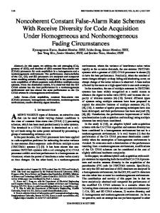
H Figure 1. Facilih dirconnect
Alarm Correlation Alarm correlation is a conceptual interpretation of multiple alarms such that new meanings are assigned to these alarms. It is a generic process that underlies different network management tasks: Compression: the reduction of multiple occurrences of an alarm into a single alarm. Count: the substitution of a specified number of occurrences of alarms with a new alarm. Suppression: inhibitinga low-priority alarm in the presence of a higher-priority alarm. Boolean: substitution of a set of alarms satisllying a Boolean pattern with a new alarm. Generalization: reference toanalarm by itssuperclass. Alarm correlation may be used for network fault isolation and diagnosis, selecting corrective actions, proactive maintenance, and trend analysis. To illustrate the use of alarm correlation. we will give anexample basedon actual events that happened on a private telecommunication network. Because of an administrative error at a primary network control center, a circuit disconnect order was incorrectly sent to a common carrier. hut soon after withdrawn. An additional error by the common carrier led to the disconnect order being carried out despite the cancellation.This meant that alivecircuitwasdisconnected,causingacatastrophic failure on a major DS3 link between city A and city B (Fig. 1). A normal facility disconnect. when performed by network operations personnel, invokes automatic loopback conditions o n digital crossconnect systems (DCSs) at both ends of the circuit. Since thisisanormal DCS behavior, the loopback conditions a r e not reported. T h e packet and voice switches having logical trunks over the disconnected circuit sent large volumes of call processing failure messages to the primary network control center. The operators puzzled for an hour before they realized what had happened. T h e task at hand was to correlate the call-processing alarms from the switches with the absence of alarms from the DCSs, and recognize that the trunk was actually disconnected. This was complicated by the incorrect record in the database showing that the circuit was live. Subjectsforcorrelationcould be any events affccting the network. These may be environmentalstat e p a r a m e t e r s, the ne two r k man age In c n t context, or events invoked by the user or external systems. Correlations are defined over a time interval o r window. When a situation is recognized and a correlation asserted, it remains active
I E t E Network
Ncnember 190.7
c2
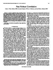
H Figure 2. (a)Conrlrrtiori o f causally dtpetiderit alanns; (b)and (c) correlu-
tiori of cuitsally iti&ptvi&tit alarms.
until it expires o r is externally cleared. Corrclations may he subsumed by higher-level correlations. The alarm correlation model introduced in thisarticle distinguishes hetwcen corrclations and c o w lation rules [ 1 I ] . A correlation is a statement about a e n t s happening on the network; for example. BadCard-Correlation states that some port contains a faulty port card. A correlation rule defines thc conditions under which correlations are asserted. Forexample, ifthcre isa redcarriergroupalarm (CGA) from one DCS. and a Yellow-CGAfrom another. and these DCSs are connected. then Bad-Card-CorreIation will be asserted. The conditional part of the rule may contain a complex Boolean pattern rccognizing alarms. NEs. and correlations, as well a s structural. temporal and other relations.
Fault Diagnosis One of the major applications of alarm correlation is network fault diagnosis. N o t all faults exhibit alarms. These faults can be recognized indirectly by correlating available alarms. Figure 2a illustrates this, showing that correlation c 1 detects the fault.fl. and correlation c? detects the fault ,f2. Correlatingcl andc3into thecorrelationcOallows diagnosis of the fault /U. Correlation between alarms due to a common fault is a transitive. reflexive. and symmetric relation (i.e.. an equivalence relation. its noted in [5]). If a single alarm is a manifestation of multiple faults, this relation may not hold. For example. if alarm a (Fig. 7b) is caused by fault fl orfaultp. but not both (anexclusive ORcondition). then correlations c.1 and e? arc formed
53
by disregarding the value of the “type” parameter. This generalization process may utilize alarm class/subclass hierarchies, which may b e built along arbitrary coordinates. An example of an alarm message class hierarchy is discussed later. The second is interpretation of simultaneous events or events happening within a predefined time interval asa qualitatively new complexsituation. The events maybe causally related or independent. During this interpretation process no faults are determined, but a more abstract specification of events is constructed.
The Conceptual Framework of Alarm Correlation
I
with acommon component alarm, and consequently the correlation relation is not transitive. If alarm U (Fig. 2c) is caused by both faultsfl andf2 (an A N D condition), correct diagnosis remains ambiguous. This may indicate a common primary fault, or independent faults causingfl andf2. In order to disambiguate these two cases, additional information is required.
Alarm Generalization Alarm generalization is potentially very useful for network management. It allows one t o deviate from a microscopic perspective of network events and view situations from a higher level. There are two ways alarm generalization may be performed. The first is subsumption of lower-level alarm classes by a higher-level class. A C G A type “ R e d ” (CGA-Red) may be generalized to alarm class CGA
-. .
SWITCH-CLASS
._ .
.
n this section the overall conceptual framework of our approach to alarm correlation is discussed. As mentioned earlier, we follow the principlesof MBR, originally used for the modeling of intelligent systems. The conceptual framework of alarm correlation contains t h e structural and behavioral components (Fig. 3 ) . The structural component is the description of t h e managed network. It contains two major parts, the network configuration model and the network-element class hierarchy. The network configuration model describes the NEs (managed objects) and the connectivity and containment relations between them. The network-element class hierarchy describes t h e N E types a n d t h e class/ subclass relationships between the types. Each NE in the networkconfiguration model is an instance of a terminal N E class from the network-element class hierarchy. T h e behavioral c o m p o n e n t describes t h e dynamics of alarm correlation. It contains three major
.
- --.
.
__I
. .. .
.
..
W Figure 4. DCS class ROCKWELL-DEXCS and instance LOS-ANGELES-DEXCS.
54
-__
IEEE Network November 1993 -
-
~
~~
“ W D .
Figure 5. Message class CARRIER-GROUP-ALARM and a sample message class hierarchy.
components: the message class hierarchy, the correlation class hierarchy, and correlation rules. The message class hierarchy describes the messages generated by NEs. The message class hierarchy is used to control the alarm message-parsing process. This process is described in more detail in [ 121. The correlation classes and correlation rules will be described later. The NE classes,message classes,correlation classes, and correlation rules are organized into hierarchies. T h e s e hierarchies a r e related by “producer/consumer” dependencies. NEs are “producers” of alarm messages, messages “produce” correlations, and rules are “consumers” of all the above. The “producer/consumer” dependencies are used by IMPACT during the application development process. These dependencies, alongwith other domain-oriented constraints, are used to support correctness, completeness, and consistency of the knowledge base, and to guide the user through the application development process. The “producer/consumer” dependency restricts the user from deleting an N E class from the knowledge base while message classes still refer to it.
The Structural Component Network Element Class Hierarchy N E classes describe network equipment types, such as switches, digital cross-connects and multiplexers. NE classes are organized into a hierarchy using class/subclass relations. T h e root of the hierarchy is a GENERIC-NE-CLASS, which contains the most general information common to all NEs. The next level of the hierarchy describes the basic NE classes, such as trunk-class, transmission-interface-class, switch-class,building-class, and others. Each of these classes refers to its own subhierarchy; for example, the trunk-class refers to the logical-trunk-class and physical-trunk-class, and the physical-trunk-class to the super-link-class, T1-trunk-class, and T3-trunk-class. Each subclass inherits parameters, values, attributes, and constraints from its superclasses. IMPACT permits multiple inheritance; that is, a class might have more than one superclass. Network Class Editor, in Fig. 4, describes ROCKWELL-DEXCS, which is a subclass of the generic digital cross-connect class DEXCS-CLASS.
IEEE Network
November 1993
Message Class refers to BASIC-DEXCS-MESSAGE, which is the root node of the associated message class hierarchy. T h e Connected Filter specifies that ROCKWELL-DEXCS may only be connected to a digital crossconnect or a switch.Within Filter is used to specify that ROCKWELL-DEXCS can be placed within a building o r a network operations center, while Contains Filter specifies that only physical and logical ports may be contained within. The NE class hierarchy is an abstraction of physical NEs. The terminal nodes describe particular NE types produced by manufacturers. Specific digital crossconnect products, such as AT&T’s DACS I1 or Rockwell’s RDX-370, are terminal nodes of the superclass digital-cross-connect-class.The NE class hierarchy is specific to an application. It may be modified by adding, deleting, or editing existing classes.The upper levelsof the hierarchy are general and are therefore reusable across applications.
The behavior a1 component contains three major components: the message class hierarchy, the correlation class hierarchy and corre ation rules
Network ConfigurationModel The network configuration model is constructed from the instances of individual NEs. NE instances describe the actual physical o r logical components of the managed network. The instances are specified by instantiating terminal NE classes and connecting them according to the network configuration. This process may be performed by the network operating staff using the IMPACT Network Element Editor. Constraints defined in the class specification will be enforced. The user cannot make connections that violate the physical behavior of the connected elements, or leave required values unspecified. Network Element Editor in Fig. 4 describes LOS-ANGELES-DEXCS, which is an instance of ROCKWELL-DEXCS. It is installed at a Los Angeles network operations center, connected to a DCS in Sacramento, and contains four physical ports.
The Behavioral Component Message Class Hierarchy All alarm messages produced by a specific NE a r e organized into a message class hierarchy using the class/subclass relation. Introduction of message classes simplifies the decision-making process of network management. Let us suppose
55
.....
action X should be taken when one of the digital crossconnect alarmsappears: CGA-Red, CGA-Blue, or CGA-Yellow. This situation could be presented by the following rule:
A correlation class is a generalized description of the state of the network based on interpretation of network events.
IF
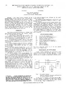
CGA-Red OR CGA-Yellow OR CGA-Blue THEN Action X The introduction of CarrierGroupAlarm as a superclass of CGA-Red, CGA-Yellow, and CGABlue allows us to write a simpler rule: IF Carrier-Group-Alarm THEN Action X A partial message class hierarchy, which corresponds to the alarm messages of a DCS, is shown in the Graph Editor Window in Fig. 5. Each message class in the hierarchy contains a message-parsing pattern and a translation schema, common to a subset of all messages that belong to this class. A trace from the root node to some class node n in the hierarchy determines a sequence of patterns t o be recognized by the parsing algorithm to detect whether incoming messages belong to the message class determined by the node n. The translation schema in the message class determines how vendor codes for this NE can be normalized to a common form, or made more readable to the network operator. The Message Class Editor in Fig. 5 describes the message class CARRIER-GROUP-ALARM.
The superclass of CARRIER-GROUP-ALARM is DS1-MESSAGE,and it has four subclasses: DEXCSCG-AAIS, DEXCS-CGA-BLUE, DEXCS-CGARED, and DEXCS-CGA-YELLOW. A fragment of the input alarm message text is stored in the slot T E X T a n d matched against the Pattern String. After successfully matching the pattern, the value of the first expression is assigned to the slot DC, and the value of the second expression is assigned to the slot FAILURE. These slots may be used by subclasses for further pattern constraints.
Correlation Class Hierarchy Acorrelation class is ageneralizeddescriptionof the state of the network based on interpretation of network events. The conditions under which the correlations are asserted are described in the correlation rules. Each assertion creates an instance of a correlation class. A correlation class contains components, a message template, and parameters (slots).The components may be NEs, alarm messages, or other correlations. Correlation components are used to pass informationfrom a correlation rule to the asserted correlation. Parametersprovide information about a correlation to higher-level correlations, of which it may be a component. Correlation BADCARD-CORRELATION, described in Fig. 6, contains two c o m p o n e n t s , a DCS, D E X C S CLASS, and a physical port, PHYSICAL-PORTCLASS. During assertion, a correlation rule assigns values to the CLLI (a universal code, which identifies the location of the equipment) and PORT-NUMBER slots. These values are
Figure 6. BAD-CARD-CORRELATION and BAD-CARD-CORRELATION-RULE-I.
-
56
IEEE Network ~
~
~~
- _ _ _ _
November 1993
used by the message template and asserted into t h e D E X C S - I D a n d P O R T - N U M B E R slots. Variable names are identified by a leading question mark.
Correlation Rules Correlation rules recognize events and assert or clear correlations. Different correlation rules may assert or clear the same type of correlation. The conditional part of a rule is a Boolean pattern built upon primary terms and relations. The primary terms are messages, NEs, correlations, and tests. The following relations are used: COUNT, CONTAINS, WITHIN, CONNECTED, arithmetic relations, and temporal relations. COUNTcounts similar events and compares the count with a predefined threshold. The counted events may be primary alarms, correlations, or complex Boolean expressions. CONTAINS and WITHIN refer t o structural containment, while CONNECTED denotes NE connectivity. The action part of the rule contains executable commands, such as the assertion and clearing of correlations. A simplified version of BADC A R D - C O R R E L A T I O N - R U L E 1 is given in Fig. 6. Time is an important correlation criterion. Correlations are determined on a fixed-length time interval. The correlation time interval may be absolute or relative. In the latter case, the time interval is considered to be a dynamic window in which alarm correlation is performed continuously. This correlation rule states: if physical ports ?near-port and ’?far-port belong to two DCSs, respectively, ?near-DEXCS and ?far-DEXCS, and these ports are connected by a T1 trunk, and Yellow Carrier Group Alarm ?yellow-msgis reported from ?far-port, and Red Carrier Group Alarm ?red-msg is reported from ?near-port, then assert BAD- CARD-CORRELATION. After matching the rule conditions, ?near-DEXCS and ?far-DEXCS are bound to particular NEs. These NEs are provided as components t o BAD-CARD-CORRELATION.
IMPACT System Description Architecture There are several requirements that underlie IMPACT design and implementation: Real-time performance. Dedication to network management tasks. Effective representation of network and correlation knowledge. User-oriented application development environment. High-level graphic user interface (CUI) idiosyncratic to network management. In the current implementation IMPACT works together with NetAlert, a real-time network management system from GTE Telecommunication Services [13] that performs primary d a t a access, collection, and preprocessing functions, such as demarcation of the beginning of each message, providing message d a t e , time, and location stamps, and performing basic event-filtering functions. NetAlert also supports International Organization for Standardization (1SO)style event reporting and logging. IMPACT’S environment could be divided into two major parts: the application development
IEEE Network -
November lY9.i
Figure 7. IMPACT architecture.
Graphical user interface
I
Alarm correlation engine
I
W Figure 8. Application run-time environment. environment and application run-time environment (Fig. 7). The application development environment supports knowledge acquisition, editing, browsing and display tools so that the network operations staff can create and maintain the network knowledge base in an efficient and safe manner. The application runtime environment provides IMPACT’S functionality to parse incoming messages, perform alarm correlation procedures, generate system actions, and provide interfaces for the network operations staff. All this functionality is supported by the network knowledge base, which contains the structural network configuration and dynamic alarm correlation models.
Application Run-Time Environment The application run-time environment monitors the networkeventsin real time, correlatesalarms, and responds to operator commands. In addition to those functions, it provides information on network status, explanations, and help. The application run-time environment consists of four major modules: the GUI, commandimessage processor, action processor, and alarm correlation engine (Fig. 8). The commandimessage processor takes incoming alarm messages, analyzes them, and turns them into objects. I t also processes the commands coming from the user. The alarm correlation engine is a rulebased system, which reasons about the messages andgeneratescorrelations. The action
57
Figure 9. Map window, message/correlation display window, and message window.
I 4 Network coifiauratron tools
Alarm co;relation tools Network arHohics tools I
1
Network
processor performs the functions determined by the correlation rules, such as displaying correlation messages, performing diagnostic procedures, storing data in a database, or executing external procedures. The command/message processor implements a novel approach to message processing based on message class hierarchies. The essence of this method is to have a universal message-parsing procedure, which can be tuned t o parse messages from different classes of NEs using associated message class hierarchies. The GUI of the application run-time environment provides the network operator several windows in which t o perform the tasks of network surveillance and fault management (Fig. 9). The map window displays the managed network, and two bad card correlation icons. The references to the corresponding messages and correlations may be seen in the messageicorrelation display window. The BAD-CARD faults happened on ports #005 and #007 in the Los Angeles DEXCS LSANCAASF. The message window displays the full text of the CGARed alarm message selected from the message/correlation display window. The operator can clear correlations or ask for
-
explanations by clicking the active correlation icon on the screen. Clicking the correlation icon opens the correlation display window, which contains a hypertextual description of the correlation. The component alarm messages, NEs, and subcorrelations are highlighted as hot areas of t h e hypertext. A mouse gesture o n these hot areas invokes a n editor describing t h e corresponding object. The operator can select any visible object on the screen and instantly examine it. The application run-time environment uses the network knowledge base created by the application development environment. The network knowledge base contains correlation classes, correlation rules, NE classes, NEs, and message classes. The network knowledge base also stores network configuration models, graphical objects for network visualization, correlation icons, and procedural scripts to be executed by the action processor.
Application Development Environment The application development environment provides powerful tools for building the network knowledge base. The core of the environment consists of eight editors, which are grouped into three sets of tools: network configuration tools, alarm correlation tools, and network graphics tools (Fig. 10). There are several features that make these editors specific t o the task of building the network knowledge base. First, the design principles of the editors are based on the general alarm correlation framework discussed earlier. The producer/consumer relationships of t h e framework a r e enforced by t h e editors. Second, tight integration between the editors allows simultaneous editing of conceptuallyrelated knowledge structures. Wherever a class or object is presented, either as text or iconically, a menu of common functions associated with that class or object is available. These menus offer choices, such as t o display that entity or access information about its relationship to others in the alarm correlationframework. Third, the editors apply telecommunication-domain knowledge by validating the correctness and completeness of entered data. If a physical port
IEEE Network
58 ~~
-~
November 1993
correlation could be defined for managing logical (virtual) networks overlaid on physical networks, or correlating network servicefaults to physical faults. Future enhancements of IMPACT will include ons e e n graphical editing of the network. This capability will allow construction of the network configuration using graphical objects and generation of the corresponding data structures. The describedevent correlation model was a strictly deterministic model. It is possible to introduce event-likelihood measurements and operations over the likelihood functions so that multiple inexact (fuzzy) correlations could be ordered according to a particular context.
Figure 11. IMPACT implementation. may only be connected to a T1 trunk, then only such trunks are offered to the user. Finally, all editors have a common look and feel, and express the idiosyncrasies of the network management domain. Network configuration tools contain two editors, the network class editor and the network element editor (Fig. 4). Alarm correlation tools contain the correlation class editor, rule editor ( Fig. 6), and message class editor (Fig. 5). The network graphicstoolsconsist of two editors, the map editor and the graph editor. The map editor shows a graphical image of the network correspondingto the network object representation. The graph editor displays object/classhierarchies of the network knowledge base (Fig. 5).
IMPACT Implementation The IMPACTimplementation (seeFig. 11)is based on the ART-IM expert system shell [14]. IMPACT uses the A R T I M forward-rule-chaining algorithm as a natural match for the eventdriven processing of a l a r m correlation, a n d the R E T E algorithm for fast pattern matching. Objects such as message classes, NE classes, NE instances and correlations are programmed as ART-IM schemas. A significant part of the system is programmed in C. The G U I and network graphics are developed in Tcl/Tk [15], a toolkit for building windowing applications. Real-time performance is central to network surveillance and fault management. Real-time networkmanagement is a "soft"real time task,where normal delays of 1 to 2 s and a maximum of 10 to 15 s are acceptable for most networks. The current implementationofthesystemonSUNSparc10 workstation parses and correlates 12to 15 alarms/s.
Conclusions and Future Work
0
ur goalwasto create an alarm correlation model and corresponding software support system that allow efficient specification of alarm correlation by the domain experts themselves.We stressed the end-user orientation of IMPACT. We wanted to lower the barrier between the network management application development process and the end user of the application, the network management personnel. IMPACT is a step towards this goal. The proposed alarm correlation model was used for three purposes: intelligent alarm filtering, alarmgeneralization, and fault diagnosis. There are other applications not discussed in this article, such as fault prediction and preventive maintenance. Interesting new applications of alarm
IEEE Network November 1993
Acknowledgments Severalpeople took part in IMPACTSdevelopment duringdifferent stagesoftheproject. MingTan developed the initial version of the map editor, which was later enhancedby Alanlemmon. Alan also developed the graph editor and the cellular network alarm correlation application. R o b e r t Weihmayer helped us to understand the telecommunication domain, and developed the initial network configuration knowledge base. Fred Atwater tested the system and helped to discover many system bugs. Finally, we would like t o thank Shri Goyal for constant e n c o u r a g e m e n t a n d suggestions on organization and content of the article.
References [ l l R. Davis, H. Shrobe. a n d W. Hamscher, "Diagnosis Based on Description of Structure a n d Function," Proc. 1982 Nat'l. Conf. Artificial Intelligence, Pittsburgh, Pa., pp.137142. 1982. [21 R. Mathone, H. Van Cotthem, and L. Vamyckeghem, "DANTES:An Expert System for Real-Time Network Troubleshooting," Proc. 10th IIcA14, Milan, Italy. pp. 527-530. Aug. 1987. 1310.Alonietal.. 'F'erformance Analpisof a n AlarmFdteIing m r tSystem," WorldCong. Exp. Sys.,vol. 4.. pp. 23462354, 1991. [4lA &ulatcr,S.&lo, and A FmkeL ''AlmmCadath and Fault Manage mentinCommuniccrtionNetworlcs."IBMRes.Rep. no.17967,May 1992. [51 I. Jordaan and M. Paterok, 'Event Correlation in Heterogeneous Networks UsingtheOSI Management Framework,"Prcc. 3rdlnt'l. Symp. IntesroredN~rkMgmt.,ScrnFrrmsisco,Calif..pp.683-696,1993. [61M. PfauWagenbauer and W. Nejdl, "Integrating Model-Based and HeuristicFeaturesinaReal-TimeExpert Systems,"E€EFapti, Intelligentsys. a n d TheirApplications, vol. 8. no. 4, pp. 1218, 1993. [71 J. Rellano et al., "GENESIS: An Expert System Shell for the Development of Symptom Pattem Recognition Expert Systems," World Cong.Exp. Sys..vol. 3, pp. 1541-1549.1991. [El W. H. Caplinger, "Objectoriented Technology in Practical Network Management Systems," Wescon '91. [91 S.B ~ g n o neti al., "An Expert System for Real-Time Fault Diagnosis of the Italian Telecommunication Network," Proc.3rd Int'l. Symp. IntegratedNetwarkMgmt.. SanFmnsiscu,Calif.,pp.617-628. 1993. I101 T. Cikosky a n d 1. Whitehill. "Integrated Network Managment S p tems: Understanding the Basics," Telecomm., vol. 6, no. 6. 1993. [ l l l G. Jakobson. R. Weihmayer, a n d M. Weissman. "A Domain Oriented Expart System Shell for Telecommunication Network Alarm Correlation," Proc. 2nd IEEE Network Mgmt. a n d Control Wksp.. Taqtown, N.Y.. Sept. 21-23, 1993. [121 G.,Jakobson a n d M. Weissman. "A New Approach to Message Processing in Distributed TMN." Proc. 4th IFIPIEEE Int'l. Wksp. on fist. Sys., Long Branch. N.J.. Oct. 5-6, 1993. 1131 "NetAlert", RealTime Analysis System," GTE Telecommunication Services, 1993. . 1LnquageFieferem,''InferenceG~n1991. [141"'ARTlMFn[151 I. Ousterhout, 'Tck An Embeddable Command Language."Proc. Winter USENIX Conf., pp. 133-146. Jan. 1990.
m....
The proposed alarm correlation model was used for three purposes: intelligent alarm filtering, alarm generalization, and fault diagnosis.
Biographies GABRIEL JAKOBSON[M '821 received a n M.S. in electrical engineering from the Tallinn Polytechnic Institute, Estonia a n d a Ph.D. in computer science from the Estonian Academy of Sciences in 1964 a n d 1971, respectively. He is a principal member of technical staff a t GTE Laboratories, Waltham. Massachusetts, where h e h a s been project leader of several expert systems a n d intelligent d a t a b a s e systems development projects. His current research interest include intelligent network management support systems. MARK D. WElSSMAN received a B.S. in chemical engineering a n d a B.A. in computer science from the State University of New York a t Buffalo in 1983 a n d 1984, respectively. He is a senior member of technical staff a t GTE Laboratories. Waltham. Massachusetts, where he h a s been a major contributor to the development of severa l expert systems for network management applications.
59


![[Book Review] - Network, IEEE - IEEE Xplore](https://m.moam.info/img/260x300/book-review-network-ieee-ieee-xplore_5b8436bd097c4762708b462d.jpg)