Algorithm 756: A MATLAB Toolbox for Schwarz-Christoffel Mapping TOBIN A. DRISCOLL Cornell University
The Schwarz-Christoffel transformation and its variations yield formulas for conformal maps from standard regions to the interiors or exteriors of possibly unbounded polygons. Computations involving these maps generally require a computer, and although the numerical aspects of these transformations have been studied, there are few software implementations that are widely available and suited for general use. The Schwarz-Christoffel Toolbox for MATLAB is a new implementation of Schwarz-Christoffel formulas for maps from the disk, half-plane, strip, and rectangle domains to polygon interiors, and from the disk to polygon exteriors. The toolbox, written entirely in the MATLAB script language, exploits the high-level functions, interactive environment, visualization tools, and graphical user interface elements supplied by current versions of MATLAB, and is suitable for use both as a standalone tool and as a library for applications written in MATLAB, Fortran, or C. Several examples and simple applications are presented to demonstrate the toolbox’s capabilities. Categories and Subject Descriptors: G.1.m [Numerical Analysis]: Miscellaneous; G.4 [Mathematics of Computing]: Mathematical Software—MATLAB; J.2 [Computer Applications]: Physical Sciences and Engineering General Terms: Algorithms Additional Key Words and Phrases: Numerical conformal mapping, Schwarz-Christoffel transformation
1. INTRODUCTION Conformal mapping has long been an important topic in complex analysis, with applications in many fields of physics and mathematics. Historically, one of the major limitations of these applications has been the difficulty of computing conformal maps for general regions. The advent of the modern computer, however, has vastly expanded the menu of regions for which conformal mapping is practical. Over the last 20 years, a few general-purpose software packages have been created for numerical conformal mapping. This research was supported in part by a National Science Foundation Graduate Fellowship, NSF grant DMS-9116110, and DOE grant DE-FG02-94ER25199. Author’s address: Center for Applied Mathematics, Cornell University, Ithaca, NY 14853; email:
[email protected]. Permission to make digital / hard copy of part or all of this work for personal or classroom use is granted without fee provided that the copies are not made or distributed for profit or commercial advantage, the copyright notice, the title of the publication, and its date appear, and notice is given that copying is by permission of the ACM, Inc. To copy otherwise, to republish, to post on servers, or to redistribute to lists, requires prior specific permission and / or a fee. © 1996 ACM 0098-3500/96/0600 –0168 $03.50 ACM Transactions on Mathematical Software, Vol. 22, No. 2, June 1996, Pages 168 –186.
A MATLAB Toolbox
•
169
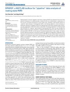
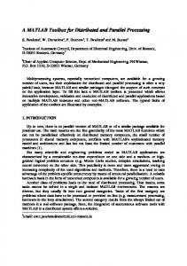
A notable example is SCPACK [Trefethen 1980; 1989], a Fortran package developed by L. N. Trefethen in the late 1970s. This package implements the Schwarz-Christoffel transformation to map between the unit disk and the interior of a polygon. Its reliability, modularity, and convenient availability have led to its use in several applications [McGrattan et al. 1994; Najm and Ghoniem 1991; Starke and Varga 1993]. Here we introduce a new Schwarz-Christoffel Toolbox for MATLAB.1 Like SCPACK, this toolbox can solve the parameter problem and compute forward and inverse maps for the Schwarz-Christoffel disk transformation. In addition, the package can use a half-plane, strip, or rectangle rather than the disk as the fundamental domain, or map between the disk and the exterior of a polygon. In keeping with the intuitive and interactive spirit of MATLAB, the Schwarz-Christoffel Toolbox lets the user draw polygons with a mouse, visualize maps quickly, and access its functions through a graphical user interface. This article is organized as follows. Section 2 introduces the SchwarzChristoffel transformation and explains the necessity of a numerical implementation. In Section 3 we summarize the algorithmic approach taken in the Schwarz-Christoffel Toolbox, and in Section 4 we cover some of the MATLAB implementation details. Section 5 presents several examples, and Section 6 demonstrates a few ways to extend and apply the toolbox. We make concluding remarks in Section 7. 2. THE SCHWARZ-CHRISTOFFEL TRANSFORMATION Suppose a polygon P has complex vertices w1, . . . , wn , given in counterclockwise order. Some of the vertices may be infinite. To each vertex wk corresponds an exterior turning angle 2bkp, or equivalently, an interior angle (1 2 bk)p. If wk Þ `, then 21 , bk # 1; otherwise, 23 , bk # 21. See Figure 1 for an illustration. Note that
O b 5 22. n
k
(1)
k51
Let C1 denote the open complex upper half-plane, and define f on C1 by
f~ z! 5 a 1 c
EP z
n21
~ s 2 x k! bk ds,
(2)
0 k51
for some real x1, . . . , x n21 satisfying
x 1 , x 2 , · · · , x n21 , x n 5 `
(3)
and complex constants a and c. Equation (2) is known as the SchwarzChristoffel formula, in honor of the two German mathematicians who 1
MATLAB is a registered trademark of The MathWorks, Inc. ACM Transactions on Mathematical Software, Vol. 22, No. 2, June 1996.
170
•
Tobin A. Driscoll
Fig. 1.
Unbounded polygon with n 5 6.
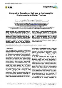
discovered it independently in the 1860s. It is not hard to see that f is analytic in C 1 \{x1, . . . , xn21} and can be extended continuously to C 1 at each xk for which bk . 21. The form of (2) guarantees that the image of the real line under f consists of straight-line segments that meet with exterior angle 2bkp at each f( x k ), 1 # k # n. Because of this we say that xk is a prevertex. We would like f( x k ) 5 w k , so that f maps the real line to P. But although the turning angle at f( x k ) matches that at wk in P, for a general set of prevertices the side lengths will be wrong, as in Figure 2. Clearly we cannot choose the prevertices and constants a and c— known collectively as the accessory parameters—arbitrarily. However, the Riemann mapping theorem guarantees that there is some conformal map from C1 to D, the interior of P, and the fundamental theorem of Schwarz-Christoffel mapping guarantees that an appropriate choice of the accessory parameters will yield such a map: THEOREM 2.1. Let D be a simply connected region bounded by a polygon having (possibly infinite) vertices w 1 , . . . , w n and exterior turning angles 2 b 1 p , . . . , 2 b n p . Then every function which maps C1 conformally onto D can be expressed in the form (2). PROOF.
See, for example, Henrici [1974, Thm 5.12e].
e
Additionally, any map as in Theorem 2.1 can be extended continuously to C (except at preimages of infinity) as a map onto D. By considering Mo¨bius transformations, we see that any three prevertices can be chosen arbitrarily. Since x n 5 `, two other prevertices, say x 1 and x 2 , may be fixed. Then the remaining prevertices, and the constants a and c, are determined uniquely by P. The Schwarz-Christoffel formula is mathematically appealing, but problematic in practice. To compute the map, one must find the prevertices by 1
ACM Transactions on Mathematical Software, Vol. 22, No. 2, June 1996.
A MATLAB Toolbox
•
171
Fig. 2. The effect of arbitrary prevertices; (a) given polygon; (b) the image of the real line under (2), for arbitrarily chosen x 1 , . . . , x 11 satisfying (3). The angles match, but the side lengths differ.
solving a system of nonlinear equations which, except in a few special cases, is analytically intractable. This is the Schwarz-Christoffel parameter problem. Furthermore, the integral in (2) rarely has a simple closed form. Finally, it is usually impossible to invert f explicitly. For these reasons, calculations involving Schwarz-Christoffel maps must generally be done on a computer. Composing (2) with standard conformal maps leads to variations of the Schwarz-Christoffel formula for mapping from other fundamental domains. The simplest such modification has the unit disk as its domain. The prevertices then lie in counterclockwise order on the unit circle, and the resulting formula is identical except that there are n rather than n 2 1 terms in the product of the integrand. Another variant is the transformation from a biinfinite strip {z : 0 # Imz # 1}, which is especially useful when P is an infinite polygonal channel, such as might arise in a fluids problem, for example. In this case the formula becomes [Howell and Trefethen 1990; Sridhar and Davis 1985; Woods 1961] as follows:
f~ z! 5 a 1 c
E
z
0
P F sinh p2 ~ s 2 z ! G n
e us
k
bk
ds,
(4)
k51
where u depends on the divergence angles at the ends of the channel, and the (complex) prevertices {zk} lie on both sides of the strip. By composing (4) with a Jacobi elliptic function, a rectangle may be used as the fundamental domain, which is appropriate when P is highly elongated in one direction. In this case the aspect ratio of the rectangle, which is the conformal modulus of the target polygon, cannot be specified in advance, but is determined by solving an appropriately constrained parameter problem on the strip (see Howell and Trefethen [1990] for details). Many other variations of the Schwarz-Christoffel transformation resulting from composition with standard maps are possible. ACM Transactions on Mathematical Software, Vol. 22, No. 2, June 1996.
172
•
Tobin A. Driscoll
By modifying the usual derivation of (2) slightly, we can also find a function which maps the unit disk onto the exterior of P [Henrici 1974]:
f~ z! 5 a 1 c
E
z
0
P ~s 2 z ! n
s 22
k
bk
ds.
(5)
k51
The term s 22 reflects a choice of mapping the origin to the point at infinity. Thus only a single prevertex may be chosen arbitrarily. Here the vertices are specified in counterclockwise order about the exterior of P, or clockwise about the interior, so that the sum in (1) is 12. Other generalizations of the basic Schwarz-Christoffel idea have also been implemented.2 3. DESCRIPTION OF THE ALGORITHMS From an algorithmic standpoint, all the variations of the Schwarz-Christoffel formula discussed in the preceding are similar. The major challenges are computing integrals of the form (2), solving the parameter problem, and, if desired, inverting (2). All these issues have been elegantly dealt with for the case of the interior disk map in Trefethen [1980], for the half-plane in Trefethen [1993], and for the strip and rectangle in Howell and Trefethen [1990]. We briefly summarize the methods used in the current package. Clearly we must be able to compute integrals of the form (2). These are nontrivial because the integrand is singular at the prevertices, and these singularities are often endpoints of the integration. The method chosen is compound Gauss-Jacobi quadrature, as described in Trefethen [1980]. Gauss-Jacobi quadrature is naturally suited to this type of endpoint singularity, and an adaptive compound implementation deals with the influence of singularities near the integration interval, which is important due to the phenomenon known as “crowding” (see Section 5). Our experience confirms the observation made by Trefethen that N integration nodes in each subinterval are enough to ensure results that are accurate to within 102N. We now turn to the parameter problem. Recall that for the half-plane formula (2), n 2 3 of the n prevertices {xk} must be determined. Because the angles are guaranteed to be correct for any set of prevertices, we must use the side lengths of P to derive n 2 3 real conditions. If all the vertices wk are finite, a natural set of conditions is as follows, according to Trefethen [1993]:
u* xxkk11 f9(s)dsu u* f9 ~ s ! dsu x2 x1
5
uw k11 2 w ku uw 2 2 w 1u
,
2 # k # n 2 2.
2
(6)
See Da¨ppen [1988], Davis [1979], DeLillo and Elcrat [1993], Floryan [1986], Floryan and Zemach [1987], Hoekstra [1986], Howell [1993], and Reppe [1979].
ACM Transactions on Mathematical Software, Vol. 22, No. 2, June 1996.
A MATLAB Toolbox
•
173
Note that the constants a and c do not appear, and the equations are scaled by a length occurring in the problem. If all n 2 3 equations are satisfied, then w1, . . . , wn21 are correctly located relative to one another, and wn is then located by the intersection of the two sides adjacent to it. As a consequence, wn may not be a finite vertex whose adjacent sides are collinear; that is, bn must not be 0 or 1. Equation (6) give us a square system of nonlinear equations, but it is a constrained system due to (3). A change of variables enforces the constraints implicitly:
y j 5 log ~ x j12 2 x j11! ,
1 # j # n 2 3.
(7)
Now we have an unconstrained square system of nonlinear equations, which can be solved numerically by a number of standard methods. The integration contours in (6) are chosen to be the real line segments between prevertices, so that the logarithms needed to compute the integrands can be done in real arithmetic. This is an advantage particular to the half-plane formulation. If a particular vertex wk is infinite, the conditions in (6) for k 5 k 2 1 and k 5 k cannot be used. Instead, we can integrate between prevertices k 2 1 and k 1 1 and replace the absolute values of the fractions with real and imaginary parts. However, in order to avoid integrating through a singularity, the integration path between x k 21 and x k 11 must pass through the upper half-plane (we choose two line segments meeting at an intermediate point), and the advantage of real logarithms is lost. Note that w1 and w2 must be finite because of their appearance in the denominators of (6). In order to avoid integrations with an endpoint at infinity, we must also require the finiteness of wn21. Occasionally these restrictions necessitate renumbering the vertices or, in rare cases, adding trivial (zero-turn) vertices. Systems analogous to (6) are solved for the disk, strip, and rectangle variations. For the disk, our approach differs slightly from that taken in SCPACK, where only one prevertex plus the conformal center (image of the origin) are fixed and where n 2 1 conditions are needed. When the fundamental domain is the strip or the rectangle, logarithms are taken in the analog of (6) in order to improve scaling, because the polygons involved are usually highly elongated; for details, see Howell and Trefethen [1990]. For the exterior mapping problem, in which n 2 1 conditions are required, the first n 2 3 conditions are of the form (6), and the remaining two real conditions come from setting the scaled residue of f 9 at the origin to zero. Finally, there is the matter of calculating f 21(w). Again, we take the approach of SCPACK. By differentiating w 5 f( z), we obtain an ODE for z with w as an independent variable. Alternatively, we can apply Newton’s method to find a root of f( z) 2 w. Often the most efficient method is to numerically solve the ODE with a large error tolerance in order to obtain a good initial guess for the Newton iteration. ACM Transactions on Mathematical Software, Vol. 22, No. 2, June 1996.
174
•
Tobin A. Driscoll
4. MATLAB IMPLEMENTATION Programs for working with half-plane, disk, strip, rectangle, and exterior maps have been written for MATLAB 4.1 in its native language. Routines are included for solving the parameter problem and computing forward and inverse maps for each variation. There are also functions for altering a disk map to accommodate an arbitrary choice of conformal center (thus all the functionality of SCPACK is included) and for converting between half-plane and disk variations. The public domain MATLAB package NESOLVE,3 which is Richard Behrens’ implementation of some of the modules in Dennis and Schnabel [1983], was chosen for solving the nonlinear system arising from the parameter problem. The algorithm used is a Gauss-Newton method with line search and Broyden update of the Jacobian. The FSOLVE package currently available in MathWorks’ Optimization Toolbox computes the Jacobian by finite differences only; the Broyden update is significantly better because of the relatively high cost of nonlinear function evaluations. Iterations are continued until the two-norm of the nonlinear function vector (e.g., Eq. (6)) is smaller than a user-adjustable tolerance. Experience indicates that the values of prevertices and function maps are then generally at least as accurate as this tolerance, and often the maps are more accurate far from the singularities. Experiments reveal that MATLAB automatically exploits the advantage of real logarithms available in solving the half-plane parameter problem. For this reason, the half-plane formulation in general executes about twice as fast as the disk formulation, although on some problems it is actually a little slower. All the toolbox code is vectorized to avoid unnecessary loops, a crucial factor affecting execution time in MATLAB. A few other measures have been taken to improve speed somewhat, but the code has not been finely tuned. Comparisons with the Fortran SCPACK indicate that the latter is usually faster at solving the parameter problem than the toolbox disk and half-plane parameter problem solvers, even though the latter have two fewer unknowns in the nonlinear system. Typically, the ratio of execution time for the toolbox to that of SCPACK is roughly two, although it varies between 0.8 and 5. The discrepancy between MATLAB and Fortran is probably unavoidable, being in part due to MATLAB’s dynamic management of memory and program flow control. Fortunately, modern computing power and the usually modest problem sizes make the speed issue fairly minor in absolute terms. Emphasis was placed on making the toolbox easy and convenient to use. The innate interactivity, vector handling, and graphics capabilities of MATLAB naturally play an important role. In addition, functions have been provided to facilitate use of the numerical core. One function allows the user to input a polygon with a mouse. It supports infinite vertices,
3
This is the same package that was distributed as FSOLVE in versions of MATLAB prior to 4.0.
ACM Transactions on Mathematical Software, Vol. 22, No. 2, June 1996.
A MATLAB Toolbox
•
175
restriction to a grid, and quantized angles and side lengths. This function has proved invaluable in exploring maps for many different regions. Also useful are adaptive plotting routines, which provide an easy way to visualize the maps by graphing the image of a customizable orthogonal mesh in the fundamental domain. Finally, virtually all the major toolbox functions are accessible both via the command line and through a graphical user interface (GUI) constructed using MATLAB’s built-in facilities. The command-line route allows precise control and incorporation of the package into other software. The GUI is well suited for experimentation. The toolbox, along with documentation, is available via anonymous ftp: ftp.cs.cornell.edu, in the directory pub/driscoll/SC-Toolbox. Inquiries may be sent to the author at
[email protected].
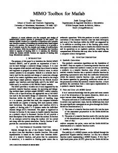
5. EXAMPLES We now present a few examples to illustrate the capabilities of the Schwarz-Christoffel Toolbox. The toolbox is also distributed with several automated demonstrations accessible through the function scdemo. Complete details on using the package are given in a user’s guide distributed with the software and in online help via MATLAB’s help and lookfor commands. All the polygons for the following figures were drawn by hand with the toolbox’s drawing function, drawpoly. This function allows the user to constrain vertices to a grid, quantize polygon angles and lengths, and place infinite vertices. Figure 3 shows the half-plane and interior disk maps for an L-shaped region. Figure 3(a) is the image of a regular rectangular mesh in the upper half-plane. The images of the vertical lines converge at one end to wn 5 f (`), and the horizontal ones converge there at both ends. Figure 3(b) is the image of a polar grid in the unit disk. Of course, all the intersections in both graphs are at right angles. Underneath each plot is a listing of lines that are entered at the MATLAB prompt or in a function file to create each picture. The listings have one line each for creating the polygon via the drawing tool, solving the parameter problem, and visualizing the result. The slightly different plotting command for the disk case stems from requiring the conformal center to be at 20.5 2 0.5i. Each of the plots in this section is produced similarly, with possibly an extra line for manually selecting the axes limits. For the half-plane case, the parameter problem solution took 1.1 seconds and the plot about 15 seconds on a SPARC-10 workstation. The corresponding times for the disk were about 2.8 and 9.4 seconds. The parameter problem times correspond to the number of nonlinear function evaluations needed: 12 for the half-plane and 30 for the disk. (This example is too simple for the advantage of real logarithms to be evident.) The plotting time for the half-plane is longer because the program must figure out how far toward infinity it must go in three directions to produce accurate and smooth curves near wn. ACM Transactions on Mathematical Software, Vol. 22, No. 2, June 1996.
176
•
Tobin A. Driscoll
(a)
(b)
Fig. 3. The half-plane (a) and disk (b) maps for an L-shaped region. The half-plane plot is the image of 10 evenly spaced vertical and 10 evenly spaced horizontal lines with abscissae from 22.7 and 15.6 (chosen automatically) and ordinates from 0.8 to 8. The disk plot is the image of 10 evenly spaced circles and radii in the unit disk. Below each plot is the MATLAB code needed to generate it.
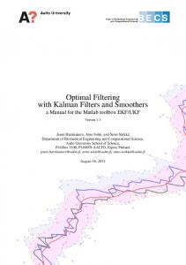
Figure 4 demonstrates the half-plane and disk maps for several polygons featuring infinite vertices and slits. Half-plane maps are often suggestive of potential flows of fluids, while disk maps typically invite interpretation as electrostatic fields due to point charges. Figure 5 shows the disk maps for two regions which have recently achieved some notoriety due to Gordon et al. [1992]. In their paper the authors answer the celebrated question, “Can one hear the shape of a drum?,” in the negative, and these regions represent their simplest counterexample. That is, the Laplacian operators with homogeneous Dirichlet boundary conditions on these regions have identical spectra. The polygons bounding the regions have the same turning angles in different orders, which leads us to speculate that the Schwarz-Christoffel maps might lend some insight into the isospectral property. Figure 6 shows a polygon which exhibits the crowding phenomenon, a well-known difficulty encountered in numerical conformal mapping. In Table I we see that the prevertices for both the half-plane and disk formulations are highly clustered. In general, the prevertices of an elongated region become crowded together in a way depending exponentially on the aspect ratio of the region. Hence it becomes impossible to distinguish prevertices in double-precision arithmetic for an aspect ratio greater than about 20. In practice even a slightly smaller aspect ratio can make convergence to the solution of the parameter problem unacceptably slow. ACM Transactions on Mathematical Software, Vol. 22, No. 2, June 1996.
A MATLAB Toolbox
•
177
Fig. 4. The half-plane (top) and disk maps (bottom) for several polygons. Except at top right, the regions are unbounded.
Crowding can be circumvented for regions which are elongated in just one direction by using a rectangle as the fundamental domain. Figure 7 exhibits the rectangle maps for two polygons for which neither the half-plane nor disk maps can be computed by the toolbox. The rectangle map can be used to compute the electrical resistance of a polygonal resistor [Trefethen 1984], because the resistance is equal to the conformal modulus of the polygon. Closely related to the rectangle map is the map from a biinfinite strip. Typically this formulation is useful when the target region is a polygonal channel, and the ends of the strip correspond to ends of the channel. Another interesting situation is when a source or sink is desired at some finite vertex of a polygon. Figure 8 demonstrates these situations. Figure 9 displays the exterior maps for two polygons. From the toolbox user’s standpoint, there is little difference from the other maps. A natural interpretation of the plots is as equipotential and field flow curves for polygonal conductors. The region on the left is an early stage in the ACM Transactions on Mathematical Software, Vol. 22, No. 2, June 1996.
178
•
Tobin A. Driscoll
Fig. 5. “Can one hear the shape of a drum?” Disk maps for regions which are isospectral with respect to the Laplacian operator with Dirichlet boundary conditions. Each plot shows the images of 12 circles with evenly spaced radii between 0.1 and 0.99 and 12 evenly spaced rays in the unit disk.
(a)
(b)
Fig. 6. (a) a polygon which exhibits crowding of the prevertices (see Table I); (b) the disk map for the region inside the dashed lines.
production of the fractal Koch snowflake and appears in the CONFPACK documentation [Hough 1990]. This polygon was drawn quite easily by hand using angle and length quantization. Because of the manifold symmetry of the region, the exterior map could be computed by solving an interior mapping problem for a sector of angle p/6 of the snowflake exterior and applying the Schwarz reflection principle. This would reduce the effective number of vertices from 48 to 6, and in principle it would speed up the solution to the parameter problem by a factor of thousands. However, using the exterior formula (5) for the full polygon, the parameter problem solution and the plot in Figure 9 each required about four minutes on a SPARC-10, so the potential gains are not large in an absolute sense. ACM Transactions on Mathematical Software, Vol. 22, No. 2, June 1996.
A MATLAB Toolbox Table I.
•
179
Prevertices for Half-Plane and Disk Maps of the Polygon in Figure 6
k
wk
Half-plane: xk
Disk: (arg zk)/p
1 2 3 4 5 6 7 8
3.2 1 2.4i 0.8 2 0.4i 20.8 2 0.4i 22.8 1 2i 22.8 2 2i 20.8 2 0.8i 0.8 2 0.8i 3.2 2 2i
21 0 0.0217140432 0.0217140885 0.0217140902 0.0217141442 0.0396571622 `
0.00800451739 0.606337224 1.49999746 1.49999860 1.49999865 1.5 1.75 2
For the half-plane, prevertices 1, 2, and 8 are fixed, while for the disk, prevertices 6, 7, and 8 are fixed. Note that many of the prevertices are quite close together, a manifestation of the crowding phenomenon.
(a)
(b)
Fig. 7. The rectangle map for two highly elongated regions. The curves are images of equally spaced lines in the interior of the rectangles. The conformal moduli of the regions are about 27.2 (a) and 91.5 (b), rendering them impossible to map from the disk or half-plane in double-precision arithmetic.
Moreover, the exterior formula also applies to regions with no symmetry, as the graph on the right in Figure 9 demonstrates. 6. EXTENSIONS AND APPLICATIONS In this section we demonstrate a few ways to extend the conformal mapping utility of the Schwarz-Christoffel Toolbox, and we present two simple applications of the exterior map. The Schwarz reflection principle was mentioned in Section 5 as a means of speeding up computations for regions with reflective symmetry. The reflection technique can also be used to compute conformal maps for regions to which the Schwarz-Christoffel formula does not directly apply. Two examples of this are exhibited in Figure 10. For periodic regions such as the one on the left (Figure 10(a)), the overall map can be constructed by ACM Transactions on Mathematical Software, Vol. 22, No. 2, June 1996.
180
•
Tobin A. Driscoll
(a)
(b)
Fig. 8. Maps from the infinite strip 0#Im z#1; (a) the ends of the strip map to the ends of the channel (compare to Figure 4); (b) one end of the strip maps to a finite point.
Fig. 9. Maps from the unit disk to two polygon exteriors. The region on the right is the complement of three connected line segments.
computing the rectangle map for the fundamental region (shown in dashed lines) and reflecting and translating the results [Floryan 1986]. Since the toolbox’s plotting routines return the coordinates of the plotted points upon request, this graph can be constructed with one plot statement per fundamental unit. Another interesting way to use reflection is for doubly connected regions with an axis of symmetry, as shown in Figure 10(b). Because the entire region maps to an annulus, half of the region maps to half an annulus, which after a logarithm becomes a rectangle. Thus Figure 10 is the result of a toolbox rectangle map and a reflection. A different method can be used to find maps to gearlike domains [Pearce 1991], such as the one shown in Figure 11(a). The simplest case is when one of the notches goes to the origin. Upon taking a logarithm, the region ACM Transactions on Mathematical Software, Vol. 22, No. 2, June 1996.
A MATLAB Toolbox
(a)
•
181
(b)
Fig. 10. Maps computed by reflections: (a) periodic with reflective symmetry at the dashed lines and mapped from a strip; (b) doubly connected with an axis of symmetry and mapped from an annulus.
(a) Fig. 11.
(b)
(a) Map from the unit disk to a gearlike domain; (b) logarithms of these curves.
becomes a notched semiinfinite strip (Figure 11(b)), for which an interior map can be computed. Figure 12 shows a simple application of exterior mapping: streamlines for two flows past a crude “airfoil.” The method is outlined in Henrici [1974, pp. 358 –367]. The situation in Figure 12(a) is flow with zero circulation, for which one stagnation point is on top of the airfoil. This plot is made by considering the model problem of flow exterior to the real interval [21, 1]. The streamlines of the model problem are horizontal lines and can be mapped to the unit disk by an inverse Joukowski map and thence to the airfoil exterior via the toolbox. Figure 12(b) is a flow with negative circulation meant to illustrate the Kutta condition. In this case the model flow is the exterior of the unit circle, which was the intermediate plane in ACM Transactions on Mathematical Software, Vol. 22, No. 2, June 1996.
182
•
Tobin A. Driscoll
(a)
(b)
Fig. 12. (a) noncirculating potential flow past an “airfoil”; (b) flow past the same airfoil with negative circulation.
the previous case. The stagnation points in the model plane are prevertices of the airfoil, and from this the streamlines can be computed in the model plane (via MATLAB’s contour command) and mapped to the airfoil exterior. One potential pitfall of applying this technique to real airfoils would be the introduction of singularities in the flow at artificial corners. However, we expect that with careful use, polygonal approximation often produces acceptable results. A completely different application of the exterior map is the computation of Faber polynomials. Let V be a bounded, connected region whose complement Vc is simply connected in the extended plane. There is a unique conformal map f which takes Vc onto the exterior of the unit disk, fixes the point at infinity, and has a positive real derivative there. The mth-degree Faber polynomial Fm for V is given by the polynomial part of the Laurent expansion of fm at infinity. When V is the interior of a bounded polygon, so that the f defined in (5) maps from the unit disk to Vc, the Faber polynomials can be computed easily from f via a recurrence relation. The Faber polynomials have a number of interesting properties, one of the most important being that they are “nearly minimax” on the region V. This property has been used as a justification for choosing Faber polynomials for approximate spectra as iteration polynomials in Krylov subspace iterations for the solution of linear systems [Starke and Varga 1993]. In Figure 13 we plot the lemniscates {z : uFm(z)u 5 1} for a particular polygon and various m. Because Fm is an analytic projection of fm, which is identically one in modulus on the polygon, the lemniscates approximate the polygon. The reentrant corners of the exterior region are resolved first, with the “deadwater” regions being most difficult. Note the tendency of the lemniscates to oscillate about the polygon edges. This is related to equioscillation, familiar from Chebyshev approximation, and the near minimality of the Faber polynomials. Figure 14 presents another look at this ACM Transactions on Mathematical Software, Vol. 22, No. 2, June 1996.
A MATLAB Toolbox
•
183
Fig. 13. Lemniscates of Faber polynomials. The solid curves are the level sets {z: u Fm (z) u 5 1} for Faber polynomials of degrees m 5 4, 8, 12, 16 for the dashed polygon. The level sets approximate the polygon better as m increases.
phenomenon, showing the absolute value of the same Fm on Feje´r points (images of roots of unity) on the polygon. 7. CONCLUSION The Schwarz-Christoffel Toolbox for MATLAB represents two principal improvements over the Fortran package SCPACK. First, it supports many more variations of the Schwarz-Christoffel transformation, including maps from the half-plane, strip, and rectangle, and maps to polygon exteriors. In particular, it offers the rectangle as an alternative for some polygons for which crowding would be prohibitive on the disk. Second, it comes with graphical input and output facilities, a graphical user interface, and is part of the interactive MATLAB environment. These improvements enhance the usefulness of the package for experimentation with the different sorts of ACM Transactions on Mathematical Software, Vol. 22, No. 2, June 1996.
184
•
Tobin A. Driscoll
Fig. 14. Size of the Faber polynomials on the polygon. The polynomials from Figure 13 are evaluated on 200 Feje´r points on the polygon and their absolute value plotted. The values oscillate about 1.
Schwarz-Christoffel maps for a large variety of polygons. At the same time, MATLAB’s computational engine services allow the package to be integrated into other functions written in MATLAB, Fortran, or C. Although some execution speed from SCPACK is sacrificed, we believe the difference to be unimportant for most applications. If speed were essential, the most significant numerical routines could be translated into Fortran or C and linked seamlessly with MATLAB. Many possibilities exist for future work. Other generalizations of the Schwarz-Christoffel transformation could be integrated into the package, such as doubly connected regions [Da¨ppen 1988], gearlike domains [Pearce 1991], circular arc polygons [Howell 1993], multiply elongated polygons [Howell 1994], and general piecewise smooth boundaries [Davis 1979]. Another possibility is to implement some other conformal mapping formula, ACM Transactions on Mathematical Software, Vol. 22, No. 2, June 1996.
A MATLAB Toolbox
•
185
such as Symm’s method for regions with piecewise analytic boundaries [Hough 1990]. By virtue of the growing acceptance of MATLAB as a numerical laboratory, we hope that the Schwarz-Christoffel Toolbox may serve to increase awareness that the Schwarz-Christoffel transformation is a practical reality.
ACKNOWLEDGMENTS
I would like to thank Nick Trefethen for his valuable suggestions regarding the software and this article. REFERENCES ¨ DAPPEN , H. D. 1988. Die Schwarz-Christoffel-Abbildung fu¨r zweifach zusammenha¨ngende Gebiete mit Anwendungen. Ph.D. thesis, ETH Zu¨rich. DAVIS, R. T. 1979. Numerical methods for coordinate generation based on Schwarz-Christoffel transformations. In Proceedings of the 4th AIAA Computational Fluid Dynamics Conference (Williamsburg, Va.). AIAA, Easton, Pa., 1–15. DELILLO, T. K. AND ELCRAT, A. R. 1993. Numerical conformal mapping methods for exterior regions with corners. J. Comput. Phys. 108, 199 –208. DENNIS, J. E. AND SCHNABEL, R. B. 1983. Numerical Methods for Unconstrained Optimization and Nonlinear Equations. Prentice-Hall, Englewood Cliffs, N.J. FLORYAN, J. M. 1986. Conformal-mapping-based coordinate generation method for flows in periodic configurations. J. Comput. Phys. 62, 221–247. FLORYAN, J. M. AND ZEMACH, C. 1987. Schwarz-Christoffel mappings: A general approach. J. Comput. Phys. 72, 347–371. GORDON, C., WEBB, D., AND WOLPERT, S. 1992. Isospectral plane domains and surfaces via Riemannian orbifolds. Invent. Math. 110, 1–22. HENRICI, P. 1974. Applied and Computational Complex Analysis. Vol. 1. John Wiley and Sons, New York. HOEKSTRA, M. 1986. Coordinate generation in symmetrical interior, exterior, or annular 2D domains, using a generalized Schwarz-Christoffel transformation. In Numerical Grid Generation in Computational Fluid Mechanics, J. Hauser and C. Taylor, Eds. Pineridge Press, Swansea, U.K. HOUGH, D. M. 1990. User’s guide to CONFPACK. ETH Zu¨rich IPS Res. Rep., ETH Zu¨rich, Switzerland, 90 –11. HOWELL, L. H. 1993. Numerical conformal mapping of circular arc polygons. J. Comput. Appl. Math. 46, 7–28. HOWELL, L. H. 1994. Schwarz-Christoffel methods for multiply-elongated regions. In Proceedings of the 14th IMACS World Congress on Computation and Applied Mathematics. North-Holland, Amsterdam HOWELL, L. H. AND TREFETHEN, L. N. 1990. A modified Schwarz-Christoffel transformation for elongated regions. SIAM J. Sci. Stat. Comput. 11, 928 –949. MCGRATTAN, K. B., REHM, R. G., AND BAUM, H. R. 1994. Fire-driven flows in enclosures. J. Comput. Phys. 110, 285–291. NAJM, H. M. AND GHONIEM, A. F. 1991. Numerical simulation of the convective instability in a dump combustor. AIAA J. 29, 911–919. PEARCE, K. 1991. A constructive method for numerically computing conformal mappings for gearlike domains. SIAM J. Sci. Stat. Comput. 12, 231–246. REPPE, K. 1979. Berechnung von Magnetfeldern mit Hilfe der konformen Abbildung durch numerische Integration der Abbildungsfunktion von Schwarz-Christoffel. Siemens Forsch. u. Entwickl. Ber. 8, 190 –195. ACM Transactions on Mathematical Software, Vol. 22, No. 2, June 1996.
186
•
Tobin A. Driscoll
SRIDHAR, K. P. AND DAVIS, R. T. 1985. A Schwarz-Christoffel method for generating twodimensional flow grids. J. Fluids Eng. 107, 330 –337. STARKE, G. AND VARGA, R. S. 1993. A hybrid Arnoldi-Faber iterative method for nonsymmetric systems of linear equations. Num. Math. 64, 213–240. TREFETHEN, L. N. 1980. Numerical computation of the Schwarz-Christoffel transformation. SIAM J. Sci. Stat. Comput. 1, 82–102. TREFETHEN, L. N. 1984. Analysis and design of polygonal resistors by conformal mapping. Z. Angew. Math. Phys. 35, 692–704. TREFETHEN, L. N. 1989. SCPACK user’s guide. MIT Numerical Analysis Rep. 89-2. MIT, Cambridge, Mass. TREFETHEN, L. N. 1993. Numerical construction of conformal maps. In Fundamentals of Complex Analysis for Mathematics, Science, and Engineering. Prentice-Hall, Englewood Cliffs, N.J. WOODS, L. C. 1961. The Theory of Subsonic Plane Flow. Cambridge University Press, Cambridge, Mass. Received September 1994; revised June 1995; accepted June 1995
ACM Transactions on Mathematical Software, Vol. 22, No. 2, June 1996.