J. E. Walter is with the Computer Science Department, Vassar College, ... The com- plete interchangeability of the robots provides a high degree of system fault ...
IEEE TRANSACTIONS ON ROBOTICS, VOL. 21, NO. 4, AUGUST 2005
621
Algorithms for Fast Concurrent Reconfiguration of Hexagonal Metamorphic Robots Jennifer E. Walter, Member, IEEE, Elizabeth M. Tsai, and Nancy M. Amato, Member, IEEE
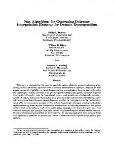
Abstract—The problem addressed is the distributed reconfiguration of a system of hexagonal metamorphic robots (modules) from an initial straight chain to a goal configuration that satisfies a simple admissibility condition. Our reconfiguration strategy depends on finding a contiguous path of cells that spans the goal configuration and over which modules can move concurrently without collision or deadlock, called an admissible substrate path. A subset of modules first occupy the admissible substrate path, which is then traversed by other modules to fill in the remainder of the goal. We present a two-phase reconfiguration strategy, beginning with a centralized preprocessing phase that finds and heuristically ranks all admissible substrate paths in the goal configuration, according to which path is likely to result in fast parallel reconfiguration. We prove the correctness of our path-finding algorithm and demonstrate its effectiveness through simulation. The second phase of reconfiguration is accomplished by a deterministic, distributed algorithm that uses little or no intermodule message passing. Index Terms—Distributed reconfiguration, metamorphic robots. Fig. 1. Metamorphic robots used to buttress a building.
I. INTRODUCTION
A
SELF-RECONFIGURABLE, or self-organizing [1], robotic system is a collection of independently controlled, mobile robots, each of which has the ability to connect, disconnect, and move around adjacent robots. Metamorphic robotic systems [2] are a subset of self-reconfigurable systems with the following characteristics. • Each module is identical in structure, motion constraints, and computing capabilities. • The modules are regular polygons or polyhedra that can form two-dimensional (2-D) and three-dimensional (3-D) solid lattices. • Robots generally achieve locomotion by moving over a substrate composed of one or more other robots.
Manuscript received September 13, 2003; revised May 20, 2004. This paper was recommended for publication by Editors S. Hutchinson and A. Maciejewski upon evaluation of the reviwers’ comments. This work was supported in part by the National Science Foundation CAREER Award CCR-9624315; NSF Grants IIS-9619850, ACI-9872126, EIA-9975018, EIA-0103742, EIA-9805823, ACR-0081510, ACR-0113971, CCR-0113974, EIA-9810937, EIA-0079874; the Texas Higher Education Coordinating Board Grant ARP-036327-017; the DOE ASCI ASAP program Grant B347886; a Department of Education GAANN fellowship; a GE Faculty of the Future fellowship; and the CRA-W Distributed Mentorship Program. J. E. Walter is with the Computer Science Department, Vassar College, Poughkeepsie, NY 12604 USA. E. M. Tsai is with the Computer Science Department, Swarthmore College, Swarthmore, PA 19081 USA. N. M. Amato is with the Computer Science Department, Texas A&M University, College Station, TX 77843-3112 USA. Digital Object Identifier 10.1109/TRO.2004.842325
Shape changing in these composite systems is envisioned as a means to accomplish various tasks, such as bridge building, structural support (see Fig. 1) [3], or stair formation. The complete interchangeability of the robots provides a high degree of system fault tolerance and such systems are even capable of “self-repair” [4]. Self-reconfiguring robotic systems are also potentially useful in environments that are not amenable to direct human observation and control (e.g., interplanetary space and undersea depths). The motion planning problem for a self-reconfigurable robotic system is to determine a sequence of robot motions to a desired required to go from a given initial configuration . goal configuration We focus on a system composed of planar, hexagonal robotic modules as described by Chirikjian [5]. We consider a distributed motion planning strategy, given the assumption of and that is a straight chain initial global knowledge of that intersects . Our distributed approach offers the benefits of localized decision making and a potentially fault tolerant system.1 Additionally, our strategy requires less communication between modules than other approaches. We have previously applied this approach to the problem of reconfiguring a straight chain to an intersecting straight chain [6] and a straight chain to a goal configuration that satisfies a general “admissibility” condition [7]. In [7], we presented a centralized algorithm to determine whether an arbitrary goal configuration is admissible 1Our algorithms do not address the issue of fault-tolerance (see Section VII for further discussion).
1552-3098/$20.00 © 2005 IEEE
622
IEEE TRANSACTIONS ON ROBOTICS, VOL. 21, NO. 4, AUGUST 2005
by finding a chain of goal cells that spans called an admissible substrate path. Informally, this is a path composed of a contiguous sequence of cells that modules can occupy and then traverse to completely fill . This paper builds on our previous work and has three main contributions. 1) We provide a formal definition of surfaces that can be traversed without collision or deadlock by hexagonal metamorphic modules moving in the same direction with minimal intermodule spacing between moving modules. In the case in which modules are moving from west to east, we call the surface an east-monotone admissible traversal surface. We use this definition to formally define admissible substrate paths. 2) We present algorithms to rank admissible substrate paths. The consideration of all paths allows flexibility and in choosing the location of the intersection of , making our reconfiguration algorithms applicable in many more scenarios than in our previous work. 3) We adapt the distributed reconfiguration algorithm presented in [7] to provide better parallelism based on the choice of substrate path. II. RELATED WORK AND PROBLEM DEFINITION In this section, we survey related work on metamorphic robots. We consider the class of 2-D and 3-D systems known as space filling [8] or substrate [9] systems, in which individual modules can move over a lattice composed of other modules. Our discussion is organized according to the following kinds of properties. • Hardware properties: Module shape and motion constraints. • Configuration properties: Feasible system shapes, connectivity, and other requirements on and . • Communication and control properties: Centralized versus distributed, synchronous versus asynchronous, message passing versus contact-only information. • Algorithmic properties: Deterministic versus probabilistic, global connectivity requirements, stopping conditions. A. Module Hardware Properties Reconfiguration algorithms have been developed for modules of different shapes, including hexagons [2], [4], [7], [10], [11], squares [12], [13], cubes [14]–[16], and rhombic dodecahedrons [17]–[19]. These algorithms are all particular to the motion constraints of the modules being considered. Two-dimensional modules, such as hexagons and squares, are capable of forming only simple planar configurations. Three-dimensional modules, such as cubes and rhombic dodecahedrons, are capable of forming a much larger variety of realistic shapes. In some cases, modules are deformable [2], [6], [7], [14], and [15], compressing or elongating to facilitate movement and then returning to their original resting shape. In other cases, the modules are rigid [4], [11]–[13], [16]–[19] and do not change shape during movement. In general, deformable modules have fewer
motion constraints than their rigid counterparts because they are able to move through smaller gaps in the lattice. Different system assumptions are made, depending on the physical capability of component modules. Modules may be able to move only themselves, or they may have enough power to push, pull, or carry other modules. If modules are capable, under their own power, of moving other modules besides themselves, many modules can move in a single time step, decreasing reconfiguration time [15] while raising concerns about load limitations and heat generated by friction [18]. B. Configuration Properties The reconfiguration space is generally divided into discrete units that are identical to the size and shape of the modules. Ideally, a reconfiguration algorithm should place no restrictions either on the shapes or relative positions of and . However, the problem of finding the optimal sequence of moves from to , both of arbitrary shape, has been shown to take time that is exponential in the number of modules [20]. Therefore, either heuristics are used to find a near-optimal probabilistic solution [4], [12], [13], [16]–[20], or the shapes of and are restricted to allow a successful deterministic approach [6], [7], [11], [14], [15]. The former strategy suffers from the possibility that the reconfiguration will not be successful, and the latter from lack of generality and extra time spent in preprocessing. Algorithms vary according to the restrictions on the relative positions of and , e.g., and may be required to overlap or have particular shapes and orientations [3], [6], [7], [11], [12], [20]. In general, restrictions on the relative positions of and limit the number of situations in which the algorithms are useful. C. Communication and Control Properties Centralized algorithms for planning the motion of metamorphic modules are presented in [2], [3], [11], [12], and [15]. In these algorithms, movements of individual modules are calculated using global knowledge of the system state throughout execution. These algorithms suffer from the existence of a single point of failure, the complications involved in maintaining a global view of the system, and lack of efficiency because module movements are sequential, not parallel. Distributed reconfiguration algorithms, presented in [4], [6], [7], [13], [14], and [16]–[19], allow modules to use only local information and possibly message passing to determine moves that will accomplish global reconfiguration. These algorithms allow as many modules as possible to move in parallel and can provide greater fault tolerance due to the lack of a single point of failure. Most of these algorithms [4], [13], [14], [16]–[19] use intermodule message passing to provide local coordination of module movement and to avoid module collision and deadlock. Others, notably our own algorithms [7], [6], require only local contact information and knowledge of module position to guide modules during reconfiguration after an initial centralized planning phase. Intermodule message passing during reconfiguration can facilitate reconfiguration with less preprocessing and fewer restrictions on and and can provide the coordination necessary for asynchronous module movement without collision. The advantage of restricting intermodule message passing during reconfiguration is that less module energy needs to be
WALTER et al.: ALGORITHMS FOR FAST CONCURRENT RECONFIGURATION
spent generating and processing messages and reconfiguration is less subject to outside interference in the form of message blocking. Algorithms presented in this paper and our previous work [7] require modules to move in synchronous rounds. Synchronized reconfiguration requires more overhead (e.g., synchronized clocks) but simplifies reconfiguration planning. D. Algorithmic Properties Deterministic planners like those presented in [6], [7], [11], [14], and [15], provide motion plans that avoid module collision and can guarantee successful reconfiguration, given that the shape of and meet certain predefined characteristics. The main disadvantage of deterministic planners is that they generally impose restrictions on the shapes of and , thereby limiting the situations in which they are useful. Probabilistic motion planners, such as the ones presented in [2]–[4], [12], [13], and [15]–[19], rely on local message passing to ensure two modules do not attempt to move into the same cell at the same time. Successful completion of general reconfigurations sometimes cannot be guaranteed with probabilistic planners due to blocking problems and module deadlock arising from the random nature of module movement. Most planners for space-filling robots, e.g., [2], [4], [6], [7], [12], [15], and [17], require the robots to form a single, connected component throughout reconfiguration. This requirement is enforced to facilitate communication, power distribution, and to reduce uncertainty. Reconfiguration algorithms are complete if they can achieve any possible shape of goal configuration. In meta-module systems [11], [15], [21], [22], each unit in the lattice is composed of a number of individual modules, moving in formation or breaking up to accomplish “tunneling” reconfigurations. The reconfiguration tasks in these meta-module systems are simplified [11], [22], and, therefore, the motion planning problem is not as hard as the one for individual modules. Vassilvitskii et al. [22] present a complete, parallel motion planning algorithm for a system composed of Telecubes, metamodules formed from eight cubic metamorphic modules similar in design to those developed by Rus et al. [15]. It is interesting to note that completeness of the reconfiguration space can at this time be guaranteed only by metamodule systems, not by any system in which modules move and occupy the lattice only as individual units. E. Our Approach In our algorithms, each robot independently determines whether it is in a movable state based on the cell it occupies in the plane, the locations of cells in the goal configuration, and on which sides it contacts neighbors. Robots move from cell to cell and modify their states as they change position. The major differences between our approach and those of other researchers are summarized below. • Our algorithms use less communication during reconfiguration. Although only contact information is transmitted between modules in the reconfiguration phase, our algorithms may cause some message passing to occur in the preprocessing phase, e.g., if a single module does the
623
preprocessing and must disseminate the ordered list of goal coordinates to all other modules.2 Alternately, every module can perform the preprocessing independently, in which case the algorithms cause no message transmission, besides contact sensing, to occur in either phase. Our purpose in restricting communication is to seek an understanding of the necessary building blocks for reconfiguration, starting with algorithms that use only contact information. Because the ordering of goal coordinates and any necessary message passing besides contact sensing is done in the preprocessing phase, we claim our reconfiguration algorithms are more communication efficient than the distributed approaches of [4], [14], [16], [18], [19], and [23]. One of our future goals is to examine the complexity trade-offs between preprocessing and message passing, can be before i.e., how complex the shapes of and message passing is required. • Our algorithms are deterministic. Unlike the probabilistic approaches of [4], [16]–[19], and [23], our motion planning strategy will always produce the intended reconfiguration from to admissible , provided that is a straight chain that intersects . • Our algorithms are particular to the motion constraints of planar, hexagonal modules. Our algorithms are distinguished from other planners, e.g., [14], [18], and [19], by the shape of the modules and the constraints on module movement we consider. While our algorithms are not readily generalized to robots with different shapes or motion constraints, a similar deterministic approach may be useful when planning reconfiguration for a variety of module types, a topic we leave for future work. In Section III, we describe the system assumptions and present definitions relating to reconfiguration of a system of hexagonal metamorphic robots. Section IV presents the algorithms used in the preprocessing phase to determine admissibility of a goal configuration, along with a graph traversal and weighting algorithm for planning the reconfiguration. Section V presents a distributed algorithm for reconfiguring a straight chain to an admissible goal configuration. In Section VI, we present experimental results. Finally, Section VII provides a discussion of our results and future work. III. SYSTEM MODEL AND DEFINITIONS The plane is partitioned into equal-sized hexagonal cells and labeled using the coordinate system shown in Fig. 2, as described by Chirikjian [2]. A. Assumptions About the Modules Our model provides an abstraction of the hardware features and the interface between the hardware and the application layer. • Each module is identical in computing capability and runs the same program. • Each module is a hexagon of the same size as the cells of the plane and always occupies exactly one of the cells. 2This
dissemination could be accomplished by wireless broadcast.
624
IEEE TRANSACTIONS ON ROBOTICS, VOL. 21, NO. 4, AUGUST 2005
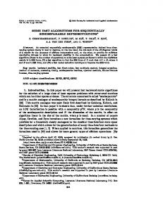
Fig. 4. Cell with SE-clearance
Fig. 2. Coordinates in a system of hexagonal cells.
� 3.
6) Modules do not move in any round in which local contact information indicates a move may partition the system (see Fig. 11 in Section V). If the algorithm does not ensure that each moving module has an immobile substrate, as specified in rule 2(b), then the results of the round are unpredictable. Likewise, the results of the round are unpredictable if the algorithm does not ensure rule 3. B. Admissible Traversal Surfaces
Fig. 3.
Before and after module movement.
• Modules do not fail. • Each module knows at all times: — its location (the coordinates of the cell that it currently occupies);3 — its orientation (which edge is facing in which direction);4 — which of its neighboring cells is occupied by another module. Modules move according to the following rules. 1) Modules move in synchronous rounds. is capable of moving to an adja2) In a round, a module (see Fig. 3) if cent cell a) cells and are currently empty; b) module has a neighbor that does not move in the round (called the substrate) and is also adjacent to cell . 3) Only one module tries to move into a particular cell in each round. 4) Modules cannot carry other modules, i.e., a module is only allowed to move itself. 5) Modules are deformable, moving by changing joint angles and rotating about a single axis while translating in the plane. 3Initial coordinates could be determined using current GPS technology, broadcast to modules via wireless transmission, and recalculated individually as modules move. 4Initial orientation information could be broadcast to modules via wireless transmission and recalculated individually as modules move.
In this section, we present a classification of traversable surfaces in a hexagonal system under the motion constraints presented in the previous section. In the interests of clarity, we will use the following abbreviations to represent directions in the grid: N (north), S (south), E (east), W (west), NE (northeast), NW (northwest), SE (southeast), and SW (southwest). In the following definition, let set represent a particular set of cells in the plane. is the number Definition 1: The d-clearance of a cell of consecutive cells that are aligned along the outgoing vector originating in the center of cell and normal to side . . Fig. 4 shows a cell with a SE-clearance Let be a contiguous sequence of distinct cells, from a set such that each cell is adjacent to the previous. The is adjacency direction between two contiguous cells and . the side of that is adjacent to Definition 2: A segment of is a contiguous subsequence of of length . In a d-segment, each cell is direction of the previous. is the end (resp. beginning) of a Definition 3: A cell d-segment if cell (resp. ) is adjacent to (resp. ) in some direction not equal to . The admissibility conditions for a traversal surface are directly related to the degree of parallelism possible, i.e., how closely modules moving across the surface can be spaced. If moving modules are separated by only a single empty cell, they will become deadlocked in acute angle corners when running our algorithms [6]. However, acute angle intersections are very commonplace in configurations of hexagonal robots. Our definition of an admissible traversal surface is, therefore, based on configuration surfaces over which moving modules with two empty cells between them can move without collision or deadlock. We present our definition of an admissible traversal surface for the situation where modules traverse the surface from west to east and then make a similar definition for the situation where traversal is from east to west.
WALTER et al.: ALGORITHMS FOR FAST CONCURRENT RECONFIGURATION
625
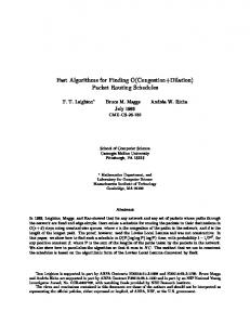
Fig. 6. Fig. 5. East-monotone admissible surfaces are shown by the shaded cells in (a) and (d). In (b), (c), (e), and (f), the black cells violate Definition 4, parts 2(a), 2(b), 3(a), and 3(b), respectively.
Definition 4: An east-monotone admissible traversal surface of distinct cells is a contiguous sequence from a set such that the following applies. 1) No is the end of a NW or SW segment (i.e., each cell is adjacent to the previous, but not to its west). 2) The north side of is such that has a) every in a N segment with NW-clearance ; NW-clearance has b) every in a S segment with NE-clearance . NE-clearance 3) The south side of is such that has a) every in a S segment with SW-clearance ; SW-clearance has b) every in a N segment with SE-clearance SE-clearance . Fig. 5 shows examples of surfaces (depicted by shaded cells) that are composed of a sequence of distinct, contiguous cells, with cells on the north side shaded in Fig. 5(a)–(c), and with cells on the south side shaded in Fig. 5(d)–(f). The cells in each of these surfaces can be numbered consecutively, from west to east, so that they adhere to Definition 4, part 1. Fig. 5(a)–(d) show the north and south sides, respectively, of east-monotone admissible traversal surfaces. Fig. 5(b)–(c) show north facing surfaces that violate parts 2(a) and 2(b) of Definition 4, respectively. Parts Fig. 5(e)–(f) show south facing surfaces that violate Definition 4 parts 3(a) and 3(b), respectively. A west-monotone admissible traversal surface is defined exactly as the east-monotone admissible surface except that in Definition 4, part 2, NW is substituted for NE and vice versa, and SE is substituted for SW and vice versa in Definition 4, part 3.
Example of (a) admissible and (b) inadmissible
G.
be the columns of , such that is the Let is the column furthest column in which intersects and . Suppose that is oriented such that column from column is the westmost column, is the eastmost column, and each column of is a contiguous straight chain oriented northsouth. Fig. 6 shows how the columns of are labeled. The assumptions concerning the relative positions of and can be made without loss of generality because if is a straight chain that is not intersecting , then the algorithms presented in [6] for straight chain to straight chain reconfiguration can be used to reorient in relation to . is assumed to be a straight chain only because this configuration is well defined. We intend to relax this assumption in future work. Definition 5: Let a path be a contiguous sequence of dis. tinct cells, In the remainder of this paper, north and south segments of may be referred to as vertical segments when it is not necessary to be more specific about direction. Definition 6: is an admissible substrate path if: 1) begins with the cell in which and overlap; 2) subsequent cells are all in ; to column ; 3) spans , from column 4) each in forms the beginning of a vertical segment only if there is no goal cell to the NE or SE of ; 5) both the north and south sides of form an east-monotone admissible traversal surface with respect to set , the set of all cells in . Definition 7: G is an admissible goal configuration if there exists an admissible substrate path in G. The purpose of finding an admissible substrate path is to divide the goal into two sections so that modules can fill both sections concurrently without collision, thereby shortening reconfiguration time. Fig. 6 depicts an example of an admissible (a) and an inadmissible (b) configuration of .
C. Admissible Goal Configurations In this section, we present a general class of goal configurations that ensure collision- and deadlock-free reconfiguration under our system model and the motion constraints on system modules. Without loss of generality, assume is a straight chain that intersects in exactly one cell on the perimeter of . The number of modules in and the number of cells in is .
IV. CENTRALIZED PRE-PROCESSING PHASE The preprocessing phase begins by finding an admissible substrate path in . This is done in two steps. 1) Construct a directed graph from . 2) Identify all possible admissible substrate paths in using a graph traversal algorithm. While traversing , weight the
626
IEEE TRANSACTIONS ON ROBOTICS, VOL. 21, NO. 4, AUGUST 2005
vertices in and calculate the cost of each possible admissible substrate path. Choose an admissible substrate path in with lowest cost and that most evenly bisects . Step 1 is done as described in [7] and is only discussed briefly in this paper. Step 2 has not been described previously. A. Constructing To construct , we first represent each goal cell as a vertex in the graph . Initially, there is an undirected edge in between each pair of adjacent goal cells in . The vertices in the graph are numbered according to the corresponding goal cell in , by column number and within columns from north to south. The algorithm that converts to a directed graph progresses from column to column, from east to west, marking the vertices that are determined to be part of an admissible substrate path leading to a goal cell in the eastmost column. Because all the representing cells in column trivially have vertices in such a path, all these cells are initially marked. When an edge down is directed from a vertex in column , for to 1, the corresponding cell in is marked. In each column , for down to 1, edges in are first directed that have eastward from vertices that correspond to cells in a marked goal cell to the northeast and/or southeast, then edges are directed northward from goal cells south of the southmost from north to south, and, finally, edges are dimarked cell in rected southward from goal cells north of the northmost marked from south to north. cell in Fig. 7 depicts the directed graph formed on a particular is marked. goal configuration, . In Fig. 7(a), column as an overlay on after every Fig. 7(b) shows the graph column of has been processed. Only marked cells on paths that span are considered for possible inclusion in an admissible substrate path and all other cells are unmarked in ; any edges directed from these cells are removed from corresponding vertices in . B. Traversing and Weighting We combine a weighting heuristic with a graph traversal algorithm for the purposes of assigning a weight to each path that spans all columns of . We describe the traversal algorithm first, then the weighting scheme. We will show that our technique traverses all potential admissible substrate paths and, thus, provides a general technique for traversing all root to leaf paths in a rooted DAG. In the following presentation of the TRAVERSEGRAPH algorithm, white vertices are those that are not visited and black vertices are visited. Because the TRAVERSEGRAPH algorithm finds all root to leaf paths in , a single vertex can be colored black while traversing toward a leaf and then white while backtracking, until all paths have been traversed. The pseudocode for TRAVERSEGRAPH and its internal procedure BACKTRACK is presented in Fig. 8. Initially, all are white and parent . The TRAVERSEGRAPH procedure is called once for each marked vertex in column . We know from our previous work in [6] that straight chains of modules in can fill in collinear straight chains or chains
Fig. 7. Example of (a) admissible goal with column directed graph formed by algorithm.
H
Fig. 8.
G
marked and (b)
Pseudocode for TRAVERSEGRAPH and BACKTRACK.
with single obtuse angle bends faster than they can fill in chains with acute angle bends. For these collinear or single bend goal configurations, we showed that the reconfiguration can be done in optimal time because modules in can initially alternate rotation directions and move from the nonintersecting end of without delay. Thus, to maximize parallelism, we designed our weighting heuristic to give the lowest weight to straight or single bend substrate paths. During each root to leaf walk, each vertex visited receives a weight specified by the weighting heuristic, described below. We assign a separate weight value to each marked vertex, , in during each root to leaf traversal on a path including , based on the direction of the incoming edge over which is currently being visited and the direction of the incoming edge over which ’s current parent is currently being visited as follows: • All vertices in columns and that have an outgoing edge are assigned weight 0. The weight at these vertices is unchanged throughout the traversal.5
I G
G
5We require that intersects at the same angle as the outgoing edge from to a cell in . Note that the intersecting chain the intersected cell in column from the north or south. will never intersect
G
G
WALTER et al.: ALGORITHMS FOR FAST CONCURRENT RECONFIGURATION
627
f) Traversing continues from vertex path information is added to set graph traversal.
Fig. 9. Example graph traversal. Darker lines indicate paths currently being traversed, small pointer indicates vertex currently being visited, numbers under vertices indicate current weight at that vertex, and contents of set are shown at leaf .
G
S
• For every vertex in columns , for each time is visited by TRAVERSEGRAPH: , — if vertex has a vertical incoming edge, ; where — else, if ’s incoming edge is directed in a different direc; tion than ’s parent’s incoming edge, — else, if ’s incoming edge is directed in the same direction . as ’s parent’s incoming edge, , for each time • For every vertex in columns . procedure BACKTRACK is called on Fig. 9 shows an example of a graph traversal with weighting of vertices. In Fig. 9, the weight is shown as a number under each vertex. A set of (cost, path) pairs is maintained at each leaf vertex in , containing the cost of every unique path starting in column and ending at leaf , along with a unique representation of path whenever is visited. For example, in Fig. 9(b), (d), and (f), a pair is added to the set at node each time is visited by TRAVERSEGRAPH. The weight value at each vertex is reset to 0 during the backtracking phase of the algorithm to ensure that a vertex’s weight is based on the correct ancestors for each unique path. Each part of Fig. 9(a)–(f) is explained below. a) After line 1 of TRAVERSEGRAPH is executed for vertex is black, while all other vertices remain white. All . vertices have b) A path from to the leaf has been traversed and all vertices along the path are black. adds the path information to its set when it is visited. c) The algorithm backtracks to vertex . Vertices and are colored white, because their respective parents have no white children. remains black, because ’s sibling, vertex , is white. Vertex weights are cleared when they are colored white. d) Traversal continues at vertex and another path to leaf is traversed. All vertices on the path are colored black and another pair is added to set at . e) The algorithm backtracks to vertex . is colored white while remains black, because ’s sibling, vertex , is white.
to the leaf and the at , completing the
Vertices in columns numbered higher than 1 with incoming edges directed to the north or south are the most heavily weighted in our algorithm because vertical edges always form substrate paths with at least two bends. If a substrate path has multiple bends, we require that the modules in that will fill the substrate path all rotate the same direction, thereby sacrificing parallelism in order to avoid collision during the reconfiguration phase. It is clear that only admissible substrate paths formed by a straight, nonvertical chain of modules will have a total cost of 0. Likewise, only admissible substrate paths with a single NE or SE bend and no vertical segments will have a cost of 1. Fig. 9(b) shows an example of a cost 1 path. From our work in [7], we know that substrate paths that evenly bisect the goal allow us to achieve the highest degree of parallelism. We thus use a second path-selection heuristic in conjunction with our weighting scheme that favors paths bisecting the goal configuration most evenly. In the event that a cost 0 or 1 path does not come within one module of evenly bisecting , higher cost paths are considered. As before, the path-selection heuristic considers higher cost paths that split the goal equally or almost equally first. C. Correctness of TRAVERSEGRAPH Theorem 1: The TRAVERSEGRAPH algorithm traverses every path in H. Proof: By induction on the number of vertices in . If the number of vertices is 1, the theorem is vacuously true because there are no edges to traverse. Suppose the theorem holds for all . graphs up to size Now consider a graph with vertices. Fix a leaf vertex, and let be the graph . By the inductive hypothesis, , so all paths in are traversed. A the theorem holds for has valid execution of the TRAVERSEGRAPH algorithm on the following properties. 1) The traversal includes a sequence of events in which is colored black and then white, possibly every vertex in signify multiple times. Suppose is a vertex in . Let the event in which vertex is colored black and let be the event in which vertex is colored white. Number the events is colored black during the execution in which vertex , where event occurs consecutively as . Number the events in which vertex is before event colored white in a similar manner. Clearly, must occur . before , which must occur before 2) By the code, each time a vertex is colored black during the execution, all children of are colored black and all children of are subsequently colored white before is colored white. 3) All children of a vertex are colored white at once. Let be a vertex in . Then let be the set of events in which the children of are colored white simultaneously. Set contains a event for each child of .
628
IEEE TRANSACTIONS ON ROBOTICS, VOL. 21, NO. 4, AUGUST 2005
Fig. 11.
Fig. 10.
Cases for proof of Theorem 1.
4) At the beginning and end of the execution, all the vertices in the graph are white. Let vertex be one of the parent vertices of in . Because are traversed after the root of is marked, it all paths in must be that all paths in the subgraph rooted at vertex are and event. So all children of traversed between each are colored black and later colored white between each and event. Fix an execution of the algorithm on and let be the sequence of coloring events during the execution. Now consider as a child of an execution where vertex is “spliced” onto vertex . • Case 1: is a leaf in . Then, can be spliced into and the sequence of events immediately after each can be spliced immediately after each to make another valid execution [see Fig. 10(a)]. . Then, can be spliced • Case 2: is not a leaf in , into the sequence of events immediately after each because the order in which the children of are colored black is not important. Because has at least 1 child in , that occurs prior to the following there must be a step event. By the code, line 5 of Procedure BACKTRACK, will be colored white along with all the other children of [see Fig. 10(b)]. If vertex has more than 1 parent in , then a similar argument holds for each parent as the one just described for a single parent . will be traTherefore, the edge from each parent of in versed each time that parent is visited, and, because edges to vertex are the only additional edges in that were not in , it must be that all paths in will be traversed by the algorithm. V. DISTRIBUTED RECONFIGURATION PHASE In this section, we describe the distributed algorithm that performs the reconfiguration of to after an admissible substrate path is found using the algorithms described in Section IV. A. Algorithm Assumptions The preprocessing phase of our approach produces an ordered list of goal coordinates. It should be noted that the compass directions specified in this section are not in absolute agreement
Contact patterns possible in algorithm.
with any real compass. Rather, the modules agree on orientation during preprocessing, forming an artificial frame of reference defined by the positions of and . The actual path taken by any module need not be explicitly calculated as long as a contiguous east-monotone admissible traversal surface composed of unmoving modules is in place between the original and final coordinates of prior to the time reaches its goal position. Therefore, the actual path discovery is entirely distributed. Initial assumptions include the following. • Each module knows the total number of modules in the . system • Each module knows the coordinates of all empty cells in , separated into three ordered lists: 1) cells on the substrate path, 2) cells north of the substrate path, and 3) cells south of the substrate path. The coordinates of cells on the substrate path are ordered from west to east, those north of the substrate path are ordered in columns from east to west and within each column from south to north, and those south of the substrate path are ordered in columns from east to west and within each column from north to south (see Fig. 13 for an example of the order in which modules fill goal cells). • Initially, one module is in each cell of . Throughout execution, each module that is not moving in a particular round is fixed in space in some orientation that is consistent with the orientation of cells in . is an admissible configuration. • • is a straight chain and and overlap in one goal cell , as described in Section III. in column B. Distributed Algorithm The algorithm works in synchronous rounds. In each round, each module determines whether it is free (see Fig. 11). In this figure, the modules labeled blocked are unable to move due to hardware constraints and those labeled free represent modules that are allowed to move in our algorithm, possibly after some initial delay. The modules in the partitioning category are restricted from moving because our algorithm ensures that the configuration is always connected, not because of hardware constraints. The pseudocode used by all free modules during each round of the reconfiguration is shown in Fig. 12. Local variables at each module include the following. • Contacts: Boolean array indicating the edges on which a module has neighboring modules. This array is assumed
WALTER et al.: ALGORITHMS FOR FAST CONCURRENT RECONFIGURATION
Fig. 12. Pseudocode executed in each round at each module to reconfigure from straight chain to admissible .
I
G
to be automatically updated at each round by some lower layer. • Position: Order of modules in , starting at the free module on the end of that does not overlap . If the module is , otherinitially free and not already in wise position is calculated by counting passing modules, incrementing position for each module that passes. • : Direction of movement, clockwise (CW) or counter clockwise (CCW). • Flips: Counter used to determine whether the module is free. • Delay: Number of time units module waits after it is free and before it makes its first move. Initially 0. Only module 1 (the module at the end of that does not overlap ) can initially determine the exact round in which it will begin moving. All modules except module 1 dynamically calculate their position in , direction of rotation, possible delay, and final coordinates in by counting the modules in initial positions further from the intersection of and as they pass, noting the direction (CW or CCW) in which the passing modules rotate. Once a module begins moving, it moves in every round until it reaches its chosen goal coordinates, using only local information about contacts with adjacent modules and its current coordinates to guide its part of the system reconfiguration. The module initially intersecting does not move. Let be the list of coordinates of goal cells on the substrate path (stored locally at each module), starting with the cell on the be substrate path adjacent to the module initially in . Let the number of initially unoccupied cells on the substrate path. Modules fill in the substrate path first. After every goal cell in is filled, modules alternate rotation directions, filling the , to west, columns projecting north and south of from east, . Modules use specific patterns of rotation and delay, as listed below. 1) (0, 0)-bidirectional: Modules alternate direction with no delay after free. 2) (1, 0)-bidirectional: Modules alternate direction with delay of 1 time unit after free for modules rotating CW and no delay after free for modules rotating CCW.
629
3) (0, 1)-bidirectional: Modules alternate direction with delay of 1 time unit after free for modules rotating CCW and no delay after free for modules rotating CW. 4) unidirectional: modules rotate same direction with delay . of 2 after free for modules in positions The reconfiguration schema uses the cost of the substrate path and proceeds as follows: or , modules 1 through use (0,0)-bidi• if starts rectional pattern and the module in position (if empty rotating in the opposite direction as module goal cells exist in that direction). Modules in positions use (1, 0)-bidirectional pattern when module starts in CW direction or (0, 1)-bidirectional patstarts in CCW direction. When tern when module there are no cells to be filled in either the CW or CCW direction, modules begin the unidirectional pattern; , modules use the unidirectional pat• if cost use (0, tern starting in the CW direction and modules 1)-bidirectional pattern until all cells either north or south of are filled. After this, modules use the unidirectional pattern, with either CW or CCW direction. The direction of rotation for module 1 for cost 0 paths is as follows: is even (resp., odd) and is slanted from SE to NW • if (resp., NE to SW), module 1 starts rotating in CW direction; • else, module 1 starts rotating in CCW direction. For cost 1 paths, the distance from module 1 to the bend in and the direction of the bend dictates the rotation direction of module 1 to avoid collision of modules on the substrate path. The direction of rotation for module 1 for cost 1 paths is as follows: • if the distance from module 1 to the bend in is even (resp., odd) and is slanted from SE to NW (resp., NE to SW), module 1 starts rotating in CCW direction; • else, module 1 starts rotating in CW direction. Fig. 13 shows six snapshots taken during the execution of the algorithm on a cost 0 path with 11 modules. Time is advancing from snapshot (a)–(f). Fig. 13(a) shows the initial positions of the modules in in relation to the goal positions. Fig. 13(b) shows how the reconfiguration begins with module 1 rotating CW and module 2 rotating CCW. Fig. 13(b)–(d) show the (0, 0)-bidirectional pattern. In Fig. 13(e), the module in pohas started the (1, 0)-bidirectional pattern, causing sition spacing of two free cells between moving modules in positions . Fig. 13(f) shows the final positions of modules after the reconfiguration is complete. VI. SIMULATION RESULTS We developed an object-oriented discrete event simulator to test our reconfiguration algorithms. During each round, the simulator checks the local status of every module, and then moves all eligible modules in the same step, thereby accurately simulating a real distributed system. In Table I, we present a sample of our experiments to determine the number of rounds used by our reconfiguration algorithm from Section V when the heuristics described in Sec-
630
IEEE TRANSACTIONS ON ROBOTICS, VOL. 21, NO. 4, AUGUST 2005
our heuristics to choose an admissible substrate path produced a reconfiguration that was within two rounds of the best overall reconfiguration time in all experimental trials. VII. CONCLUSIONS AND FUTURE WORK
Fig. 13. Example execution of the reconfiguration algorithm on a cost 0 substrate path.
TABLE I NUMBER OF ROUNDS USED FOR RECONFIGURATION FOR VARIOUS SHAPES AND SIZES OF . SHADED CELLS REPRESENT ADMISSIBLE SUBSTRATE PATHS CHOSEN BY OUR ALGORITHMS FROM SECTIONS IV.
G
This paper presents a definition of surfaces over which hexagonal modules under the motion constraints described in Section III can move, in parallel, when each pair of moving modules is separated by two free cells. We call such surfaces east-monotone admissible traversal surfaces because the definition can apply to any surface in the hexagonal grid that permits module movement. We used the definition of east-monotone admissible traversal surfaces to refine our definition of an admissible substrate path. We presented a strategy for finding a substrate path that permits flexibility in choosing a point of intersection between the initial and the goal configuration and that can decrease the number of rounds used under our strategy for reconfiguration. We introduced an algorithm for traversing all paths from root to leaf in a rooted directed acyclic lattice and proved the algorithm’s correctness. We also presented two heuristics for ranking substrate paths and selecting candidate paths based on path straightness and on how evenly the path bisects the goal. Through simulation, we demonstrated the effectiveness of these heuristics in producing plans for reconfiguration that were within two rounds of the best overall plan. We are currently working on algorithms for reconfiguration when one or more obstacles are present in the goal configuration. This work can possibly be extended to include module crash failure if failed (unmoving) modules in the goal configuration are treated like obstacles. A more comprehensive approach to fault tolerance and the extension of our algorithms to the 3-D case and to systems in which modules move under different motion constraints are subjects for future work. REFERENCES
tion IV were used to find an admissible substrate path. Only a small representative sampling of goal shapes and sizes tested are shown in Table I. The lowest and highest number of rounds used by our reconfiguration algorithm for all possible choices of admissible substrate path are also shown in this table. Note that
[1] T. Fukuda and Y. Kawauchi, “Cellular robotic system (CEBOT) as one of the realization of self-organizing intelligent universal manipulator,” in Proc. IEEE Int. Conf. Robotics and Automation, Cincinatti, OH, May 1990, pp. 662–667. [2] G. Chirikjian, “Kinematics of a metamorphic robot system,” in Proc. IEEE Int. Conf. Robotics and Automation, San Diego, CA, May 1994, pp. 449–455. [3] A. Pamecha, I. Ebert-Uphoff, and G. Chirikjian, “Useful metrics for modular robot planning,” IEEE J. Robot. Automat., vol. 13, no. 4, pp. 531–545, Aug. 1997. [4] S. Murata, H. Kurokawa, and S. Kokaji, “Self-assembling machine,” in Proc. IEEE Int. Conf. Robotics and Automation, San Diego, CA, May 1994, pp. 441–448. [5] G. Chirikjian, A. Pamecha, and I. Ebert-Uphoff, “Evaluating efficiency of self-reconfiguration in a class of modular robots,” J. Robot. Syst., vol. 13, no. 5, pp. 317–338, 1996. [6] J. Walter, J. Welch, and N. Amato, “Distributed reconfiguration of metamorphic robot chains,” in Proc. ACM Symp. Principles of Distributed Computing, Portland, OR, Jul. 2000, pp. 171–180. [7] , “Concurrent metamorphisis of hexagonal robot chains into simple connected configurations,” IEEE J. Robot. Automat., vol. 18, no. 6, pp. 945–956, Dec. 2002. [8] S. Murata, E. Yoshida, A. Kamimura, H. Kurokawa, K. Tomita, and S. Kokaji, “M-tran: Self-reconfigurable modular robotic system,” IEEE/ASME Trans. Mechatron., vol. 7, no. 4, pp. 431–441, Dec. 2002. [9] A. Casal and M. Yim, “Self-reconfiguration planning for a class of modular robots,” in Proc. SPIE Symp. Intelligent Systems and Advanced Manufacturing, Boston, MA, Sep. 1999, pp. 246–256.
WALTER et al.: ALGORITHMS FOR FAST CONCURRENT RECONFIGURATION
[10] A. Dumitrescu, I. Suzuki, and M. Yamashita, “High speed formations of reconfigurable modular robotic systems,” in Proc. IEEE Int. Conf. Robotics and Automation, Washington, DC, May 2002, pp. 123–128. [11] A. Nguyen, L. Guibas, and M. Yim, “Controlled module density helps reconfiguration planning,” in Proc. New Directions in Algorithmic and Computational Robotics, Hanover, NH, Mar. 2001, pp. 23–26. [12] C. J. Chiang and G. Chirikjian, “Similarity metrics with applications to modular robot motion planning,” Auton. Robot. J., vol. 10, no. 1, pp. 91–106, 2001. [13] K. Hosokawa, T. Tsjumori, T. Fujii, H. Kaetsu, H. Asama, Y. Kuroda, and I. Endo, “Self-organizing collective robots with morphogenesis in a vertical plane,” in Proc. IEEE Int. Conf. Robotics and Automation, Leuven, Belgium, May 1998, pp. 2858–2863. [14] Z. Butler, S. Byrnes, and D. Rus, “Distributed motion planning for modular robots with unit-compressible modules,” in Proc. IEEE Int. Conf. Intelligent Robots and Systems, Wailea, HI, Oct./Nov. 2001, pp. 790–796. [15] D. Rus and M. Vona, “Crystalline robots: Self-configuration with compressible unit modules,” Auton. Robot. J., vol. 10, no. 1, pp. 107–124, 2001. [16] E. Yoshida, S. Murata, H. Kurokawa, K. Tomita, and S. Kokaji, “A distributed reconfiguration method for 3D homogeneous structure,” in Proc. IEEE Int. Conf. Intelligent Robots and Systems, Victoria, BC, Canada, Oct. 1998, pp. 852–859. [17] H. Bojinov, A. Casal, and T. Hoag, “Emergernt structures in modular self-reconfigurable robots,” in Proc. IEEE Int. Conf. Robotics and Automation, San Francisco, CA, Apr. 2000, pp. 1734–1741. [18] M. Yim, J. Lamping, E. Mao, and J. G. Chase, “Rhombic dodecahedron shape for self-assembling robots,” Xerox PARC SPL, Tech. Rep. P9 710 777, 1997. [19] M. Yim, Y. Zhang, J. Lamping, and E. Mao, “Distributed control for 3D metamorphisis,” Auton. Robot. J., vol. 10, no. 1, pp. 41–56, 01. [20] G. Chirikjian and A. Pamecha, “Bounds for self-reconfiguration of metamorphic robots,” in Proc. IEEE Int. Conf. Robotics and Automation, Mineapolis, MN, Apr., 1996, pp. 1452–1457. [21] K. Prevas, C. Unsal, M. Efe, and P. Khosal, “A hierachial motion planning strategy for a uniform self-reconfigurable module robotic system,” in Proc. IEEE Int. Conf. Robotics and Automation, Washington, DC, May 2002, pp. 787–792. [22] S. Vassilvitski, M. Yim, and J. Suh, “A complete, local and parallel reconfiguration algorithm for cube style modular robots,” in Proc. IEEE Int. Conf. Robotics and Automation, Washington, DC, May 2002, pp. 117–122. [23] E. Yoshida, S. Murata, K. Tomita, H. Kurokawa, and S. Kokaji, “Distributed formation control of a modular mechanical system,” in Proc. IEEE Int. Conf. Intelligent Robots and Systems, Grenoble, France, Sep. 1997, pp. 1090–1097.
Jennifer E. Walter (M’93) received the B.A. degree from the University of Minnesota, Morris, in 1993, and the M.S. and a Ph.D. degrees from Texas A&M University, College Station, in 1997 and 2000, respectively. She is currently an Assistant Professor in the Department of Computer Science, Vassar College, Poughkeepsie. Her research involves the development and simulation of distributed algorithms for mobile ad hoc networks and self-reconfigurable robotic systems.
631
Elizabeth M. Tsai received the B.A. degree in computer science and Latin from Swarthmore College, Swarthmore, PA, in May 2002. She was an undergraduate student at Swarthmore College during this research collaboration, working in the CRA-W Distributed Mentor Program during the summers of 2001 and 2002.
Nancy M. Amato (M’02) received the B.S. and A.B. degrees in mathematical sciences and economics, respectively, from Stanford University, Stanford, CA, in 1986, the M.S. degree in computer science from the University of California, Berkeley, in 1988, and the Ph.D. degree in computer science from the University of Illinois at Urbana-Champaign in 1995. She is a Professor of Computer Science at Texas A&M University, College Station. Her main areas of research focus on motion planning, high-performance computing, and computational biology and geometry. Her current projects include the development of a new technique for approximating protein folding pathways and energy landscapes, and STAPL, a parallel C++ library enabling the development of efficient, portable parallel programs. Dr. Amato was an AT&T Bell Laboratories Ph.D. Scholar, and she is a recipient of a CAREER Award from the National Science Foundation. She is an Associate Editor of the IEEE TRANSACTIONS ON ROBOTICS AND AUTOMATION and the IEEE TRANSACTIONS ON PARALLEL AND DISTRIBUTED SYSTEMS. She sits on review panels for NIH and NSF, and she regularly serves on conference organizing and program committees. She is a member of the Computing Research Association’s Committee on the Status of Women in Computing Research (CRA-W) and she co-directs the CRA-W’s Distributed Mentor Program (http://www.cra.org/Activities/craw/dmp/).