Dec 10, 2008 - arXiv:0812.1900v1 [physics.optics] 10 Dec 2008. All-optical memory ... ory function with greater than 35 dB intensity contrast. We explain the ...
All-optical memory based on the injection locking bistability of a two-color laser diode S. Osborne, K. Buckley, A. Amann, and S. O’Brien
arXiv:0812.1900v1 [physics.optics] 10 Dec 2008
Tyndall National Institute, University College, Lee Maltings, Cork, Ireland We study the injection locking bistability of a specially engineered two-color semiconductor FabryP´erot laser. Oscillation in the uninjected primary mode leads to a bistability of single mode and two-color equilibria. With pulsed modulation of the injected power we demonstrate an all-optical memory element based on this bistability, where the uninjected primary mode is switched with 35 dB intensity contrast. Using experimental and theoretical analysis, we describe the associated bifurcation structure, which is not found in single mode systems with optical injection. PACS numbers: 42.55.Px, 42.65.Sf, 85.60.Bt
INTRODUCTION
Much current research in optical device physics is focused on bistable, switchable semiconductor lasing elements. The aim is to provide sophisticated functions for all-optical signal processing, including optical memory, flip-flop or optical logic [1-4]. The systems considered comprise single [3] or coupled [1, 5] devices including micro-cavity lasers [6], edge-emitting devices [7] and VCSELs [8-10]. Although laser diodes are known to exhibit complex dynamical features, they are nevertheless successfully modeled by surprisingly low-dimensional and generic systems of equations. Laser diodes therefore provide model systems for the understanding of fundamental concepts of nonlinear dynamics, such as non-invasive chaos control [11] or synchronisation of coupled chaotic systems [12]. Switching between co-existing states of bistable semiconductor laser devices can be achieved using modulated or pulsed optical injection. The structure of the bifurcations in single mode semiconductor lasers with optical injection are well understood. For a recent review see reference [13]. While two-mode models have successfully explained the switching between single mode states with different polarizations in VCSELs [14], a general understanding of nonlinear dynamical phenomena in laser diodes for the case of more than one simultaneously active mode is still lacking. In edge-emitting lasers a reason for this is that plain edge-emitting Fabry-P´erot (FP) laser diodes will generally operate with many longitudinal modes close to threshold, which complicates the interpretation and modeling of experimental results considerably [15, 16]. Using an inverse problem solution [17], which relates the threshold gain modulation in wavenumber space to the spatially varying refractive index in a FP laser, we have designed a two-color FP laser diode with THz primary mode spacing. The large engineered mode spacing of this two-color device leads to weakly coupled modes with the result that the bias current can be adjusted so that the two primary modes oscillate simultaneously with the same average power level. With only two active
modes, such a device represents a test-bed for the systematic study of the nonlinear dynamics of multiwavelength semiconductor lasers. In this paper, we examine the locking bistability of the two-color device with optical injection. In contrast to the case of a single mode laser, where a bistability is found between a stable limit cycle associated with wave mixing and the injection locked state [13, 18], we demonstrate that in the two-color laser a bistability between the injection locked (single mode) state and a two-color steady state is possible. We experimentally demonstrate alloptical switching between these bistable states, where the uninjected mode of the device performs an inverted memory function with greater than 35 dB intensity contrast. We explain the underlying mechanism using modeling and bifurcation analysis, showing that a four-dimensional model of the system provides excellent agreement with experimental results. Our results demonstrate a new and unique approach to in-plane all-optical signal processing. EXPERIMENTAL RESULTS
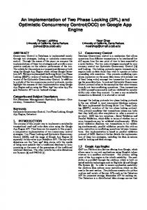
The device we consider is a multi-quantum well InP/Inx Gay Al1−x−y As FP laser of length 350 µm with a peak emission near 1.3µm. It incorporates slotted regions etched into the laser ridge waveguide that determine the lasing mode spectrum. Further details of the design and free running lasing characteristics of the device can be found in [19]. Adjusting the device current, we equalize the time averaged optical power in each primary mode of the free running laser. The primary mode spacing between the short wavelength mode ν1 and the long wavelength mode ν2 is chosen as four fundamental FP modes (480 GHz). For our experiment, we use the two-colour laser in a master-slave configuration, where the master laser is a tunable laser with < 100 kHz linewidth. A hysteresis loop of the light output power in mode ν1 for increasing and decreasing injected power in mode ν2 is shown in Fig. 1. In the insets of Fig. 1 we show the co-existing states associated with the locking bistability. The injected mode ν2 is at long wavelength and the detuning
wavelength (nm)
ν1
ν2
0
15 −10
10
ν2
1296
1298
1300
wavelength (nm)
frequency (GHz)
ν2
intensity (10 dB/div)
intensity (10dB/div)
20
ν1
1298.5 1299 1299.5
intensity (10 dB/div)
intensity (10 dB/div)
2
5 −20
0 20 15
−30
10 5
1296
1298
−40
1300
wavelength (nm)
injected power (arb. units) FIG. 1: The optical power of the short wavelength mode, ν1 , as a function of the injected power at the long wavelength mode, ν2 , in up and down sweep as indicated by the arrows. The lower left inset shows the two color equilibrium state. The upper left inset shows the injected mode in this state in close-up where a two-peak structure is seen. These peaks are separated by the detuning frequency. The right inset shows the single mode locked state of the device.
in this case is ∆ω = −14 GHz, which is approximately 3.5 times the relaxation oscillation frequency, νRO = 3.9 GHz. For weak injection the dynamics are two mode and time-periodic due to the wave-mixing response. At large injection, single mode oscillation with locking of the output to the injected light is observed. Decreasing the optical injection from inside the locking region, the single mode locking state and a two-color state are found to co-exist. In the two-color state we find that the uninjected mode has a greater intensity than the injected mode, whose spectrum (upper left inset of Fig. 1) comprises two distinct peaks, which are separated by the detuning of the injected light frequency from the free running cavity mode frequency. The optical spectra in Fig. 1 are complemented by the mode resolved power spectral densities depicted in Fig. 2. We observe four regions of qualitatively different dynamics, the boundaries between which we have indicated using corresponding values of injected field strength Ki , i = 1, 2, 3. At weak injected power (injected field strength K < K1 ) we find a two-mode wave-mixing region where the detuning frequency is observed in the dynamics of the injected mode and a weak feature at the relaxation oscillation frequency is observed in the dynamics of the uninjected mode. With increasing injected power (K1 < K < K3 ) this feature in the uninjected mode becomes considerably stronger and at the same time the peak at the detuning frequency in the dynamics of the injected mode broadens. At large injected power (K > K3 ) we enter the single mode locking region where the spectrum is structureless. For K2 < K < K3 we identify a region of optical bistability between a two-mode and a
0
0
K
1
K2
K3
0
K
1
injected power (arb. units)
K2
K
3
FIG. 2: Power spectral densities (PSD) of each of the primary modes of the device as a function of the injected power. The upper panel shows the PSD for increasing injection, while the lower panels show the PSD for decreasing injection. The frequency detuning is ∆ω = -14 GHz and the relaxation oscillation frequency is νRO = 3.9 GHz. Left panels: uninjected mode, ν1 . Right panels: Injected mode, ν2 .
single mode state. The selected stable state depends on the sweeping direction. We have been able to switch between these two bistable states using an appropriate pulsed modulation of the injected signal. The experimental setup and the mode resolved time traces in response to optical injection modulation with 5 ns pulse width are shown in Fig. 3. One can see that the device operates as a memory element where we can regard the mode at short wavelength as performing the (inverted) memory function and the injected mode at long wavelength as the writing channel. In particular, the intensity of the uninjected mode is switched between an “off” state and an “on” lasing state with a contrast ratio of greater than 35 dB.
MODELING AND BIFURCATION ANALYSIS
To understand the structure of the bifurcations that lead to this bistability we have adapted the well known model of a single mode laser [20] with optical injection to account for the presence of a second lasing mode. The system of equations in normalized units may be written as follows: E˙ 1 = 21 (1 + iα)(g1 (2n + 1) − 1)E1 (1) � �1 ˙ E2 = 2 (1 + iα)(g2 (2n + 1) − 1) − i∆ω E2 + K (2) P (3) T n˙ = P − n − (1 + 2n) m gm |Em |2
where the nonlinear modal gain is (0) gm = gm
1+ǫ
X n
βmn |En |2
!−1
.
(4)
3 ν1
(a) H2
intensity (arb. units)
ν2
H2
H1
+
-
H1
-5
SN
ν2
-10
(b) SN -
H2 H2
injection
0
+
-
-15
+
H2 0
detuning, ∆ω (GHz)
intensity (arb. units)
ν1
0.01
0.02
injection (K )
-
+
SN
0.01
0.02
(c) H2 0.03
0
-20 0.03
injection (K)
time (10 ns/div) FIG. 3: Left panel: The experimental setup schematic for the all-optical memory element device operation; PC, polarization controller; A.M., amplitude modulator; BS, beam splitter; L, lens; I, isolator; G, grating. Right panels: The intensity time traces of the uninjected mode, ν1 , the injected mode, ν2 , and of the injected field strength. The pulse duration is 5 ns.
(0)
In the above equations, gm is the linear modal gain while the ǫβmn determine the cross and self saturation. The normalized complex electric field amplitudes of the modes are given by Em and the normalized excess carrier density is n. T = γτs , where τs is the carrier lifetime and γ is the cavity decay rate. The phase-amplitude coupling is given by α while P is the normalized pump current. The bifurcation parameters are the normalized injected field strength K and the angular frequency detuning ∆ω. Parameters used are α = 2.6, P = 0.25, (50 % above threshold), T −1 = 0.00125, ǫ = 0.01, β12 = β21 = 2/3 and β11 = β22 = 1. This ratio between the cross and self saturation is consistent with the stability of the twomode solution in the free running laser [19]. Note that although we have provided a complex equation for the field E1 , the phase of E1 is in fact decoupled leading to a four-dimensional system of equations. Only the intensity of the uninjected mode influences the dynamics, reflecting the fact that the mode spacing is in the highly non-degenerate regime. More generally, our model describes two oscillators, whose amplitudes are coupled via a global variable n, and where one of the oscillators is forced by a periodic external input. Using the model equations (1)–(3), we can uncover the bifurcation scenario which is responsible for the observed bistable behaviour. In Fig. 4 (a) and (b) the local extrema of the numerically calculated field intensities |E1 |2 and |E2 |2 are shown for increasing and decreasing K and fixed ∆ω. The bifurcations evident in Fig. 4 (a) and (b) can be understood from the global bifurcation diagram in the ∆ω vs. K plane shown in Fig. 4 (c), which was calculated using the numerical continuation tool AUTO07p [21]. As K increases from zero, the stable two mode limit cycle associated with ∆ω which exists for small K
FIG. 4: Local extrema of the field intensities (a) |E1 |2 and (b) |E2 |2 obtained from numerical integration of Eqs. (1)– (3) as a function of the injected field strength for increasing and decreasing injection. The frequency detuning is -14 GHz. (c) Bifurcation diagram in the ∆ω vs. K plane. Subcritical and supercritical Hopf bifurcations are indicated by dashed − + and solid blue lines and labeled via Hm and Hm , respectively. H1± and H2± denote Hopf bifurcations of single and two mode equilibria, respectively. The solid black line SN is the saddlenode bifurcation of the single mode locked state.
evolves into a stable two mode equilibrium via a supercritical Hopf bifurcation at H2+ . With increasing K this two mode equilibrium becomes unstable via the subcritical Hopf bifurcation at H2− . On the other hand, however, the single mode locked state becomes stable via a saddlenode bifurcation at the line SN (cf. Fig. 4 (c)). Bistability therefore occurs if the SN bifurcation occurs at a smaller K value than the H2− bifurcation, which is the case for sufficiently negative detuning (∆ω < −10GHz) as evident from Fig.4 (c). This explains the hysteresis loops found in Fig. 4 (a) and (b). We are now in a position to connect our numerical findings in Fig. 4 with the experimental results of Fig. 2. For sufficiently large ∆ω, the four eigenvalues of the Jacobian matrix of the two-mode equilibrium comprise two complex conjugate pairs with imaginary parts equal to the detuning frequency ∆ω and the relaxation oscillation frequency νRO . We identify the boundary K1 in Fig. 2 with the supercritical Hopf bifurcation H2+ in Fig. 4. At H2+ the real parts of the eigenvalues associated with ∆ω change sign and become negative with increasing K. Experimentally this is reflected in a significant broadening of the spectral feature at frequency ∆ω in the dynamics of the injected mode. This is consistent with the expected behaviour in a noisy system and explains the observed double peak structure in the optical spectrum shown in the upper left inset of Fig. 1. We identify the upper boundary of the bistable region K3 in Fig. 2 with the subcritical Hopf bifurcation H2− of Fig. 4. At H2− the real parts of the eigenvalues associated with νRO change sign. Within the bistable region, spontaneous emission noise is able to excite precursor oscillations at νRO which
ν1
ν2
injection (K )
are visible in the power spectra of both modes in Fig. 2. Finally, the lower end of the bistable region K2 in Fig. 2 can be identified with the saddle-node bifurcation SN in Fig. 4. When approaching this bifurcation with decreasing K, no precursor oscillations are observed, as saddlenode bifurcations do not generically involve oscillatory behaviour. All of the above conclusions are confirmed by numerical simulations that include spontaneous emission noise. It is interesting to compare this bifurcation structure with others considered in the literature. In [13] a bistability between a limit cycle and a locked state was reported in optically injected single mode lasers. This limit cycle becomes unstable via a subcritical torus bifurcation. In contrast, our bistability mechanism involves only Hopf and saddle-node bifurcations and occurs between two equilibria. The relative simplicity of our bifurcation scenario is therefore a result of the presence of the second lasing mode, and the increase of the dimensionality of the dynamical system by one. A pair of subcritical and supercritical Hopf bifurcations have also been associated with relaxation-oscillation and wave-mixing pulsations in the context of in-plane semiconductor lasers with integrated optical feedback [22] where similar precursor features close to the bifurcation points were also reported. The bifurcations of a two-mode system have also been studied in the context of optically injected VCSELs to explain the switching between single-mode states with different polarizations [14]. However, since the two polarization modes in a VCSEL have a very small frequency spacing (c. 10 GHz), these polarization modes are intrinsically bistable, and a six dimensional system of equations is required for adequate modeling. As a result the bifurcation scenario differs significantly from that considered here, which involves an equilibrium state with two simultaneously active and highly nondegenerate lasing modes. We note also that the case of two-mode injection locking in an optically injected VCSEL [23] must also be contrasted with our case, as injection locking implies a frequency degeneracy between the orthogonally polarized modes and the injected field. Such a state, which can be regarded as a single mode state with elliptical polarization, cannot arise in the context of our model as the phase of the uninjected mode is decoupled. In Fig. 5 we show the results of numerical modeling of the optical memory element. For this simulation we have used a 5 ns pulse duration and we also included spontaneous emission noise. Agreement with the measured intensity time traces is very good. In particular, we have reproduced the large and decaying relaxation oscillations in the injected mode’s unlocking dynamics. The fast locking of the injected mode and the fast extinction of the uninjected mode is also reproduced as is the rather slower recovery of the uninjected mode once the injected mode unlocks. Numerical results suggest that the memory ele-
intensity (arb. units)
4
time (10 ns/div)
FIG. 5: Numerical intensity time traces of the injected field strength and of the two primary modes of the device. The detuning is -14 GHz. The average value of the injected field strength is 0.018 with a modulation of ± 0.008. The pulses are 5 ns duration with a 200 ps rise-time.
ment can be switched between states with subnanosecond pulses.
CONCLUSIONS
We have demonstrated an all-optical memory element based on the injection locking of a two-color Fabry-P´erot laser diode. Pulsed modulation of the injected field leads to switching of the uninjected mode with 35 dB intensity contrast. The underlying bistability in the system was found to be between the single mode injection locked state and a two-color equilibrium state, unlike in the single mode injected laser. Numerical modeling of the switching dynamics was in excellent agreement with experimental results. The simplicity of our approach should lead to new opportunities for all-optical signal processing with in-plane semiconductor lasers.
Acknowledgements
This work was supported by Science Foundation Ireland and IRCSET. The authors thank G. Huyet and S. P. Hegarty for helpful discussions and Eblana Photonics for the preparation of sample devices.
[1] M. T. Hill, H. J. S. Dorren, T. de Vries, X. J. M. Leijtens, J. H. den Besten, B. Smalbrugge, Y. S. Oei, H. Binsma, G. D. Khoe, and M. K. Smit, “A fast low-power optical memory based on coupled micro-ring lasers,” Nature 432, 206–209 (2004).
5 [2] S. Ishii and T. Baba, “Bistable lasing in twin micordisk photonic molecules,” Appl. Phys. Lett. 87, 181102 (2005). [3] M. Raburn, M. Takenada, K. Takeda, X. Song, J. S. Barton, and Y. Nakano, “Integrable multimode interference distributed Bragg reflector laser all-optical flipflops,” IEEE Photonics Tech. Lett. 18, 1421–1423 (2006). [4] S. V. Zhukovsky, D. N. Chigrin, A. V. Lavrinenko, and J. Kroha, “Switchable lasing in multimode microcavities,” Phys. Rev. Lett. 99, 073902 (2007). [5] Y. D. Jeong, J. S. Cho, Y. H. Won, H. J. Lee, and H. Yoo, “All-optical flip-flop based on the bistability of injection locked Fabry-Perot laser diode,” Optics Express 14, 4058–4063 (2006). [6] Z. Wang, G. Verschaffelt, Y. Shu, G. Mezosi, M. Sorel, J. Danckaert and, S. Yu, “Integrated small-sized semiconductor ring laser with novel retro-reflector cavity,” IEEE Photonics Tech. Lett. 20, 99–101 (2008). [7] F. Ramos, E. Kehayas, J. M. Martinez, R. Clavero, J. Marti, L. Stampoulidis, D. Tsiokos, H. Avramopoulos, J. Zhang, P. V. Holm-Nielsen, N. Chi, P. Jeppesen, N. Yan, I. Tafur Monroy, A. M. J. Koonen, M. T. Hill, Y. Liu, H. J. S. Dorren, R. Van Caenegem, D. Colle, M. Pickavet, and B. Riposati, “IST-LASANGE: Towards all-optical label swapping employing optical logic gates and optical flip-flops,” J. Lightwave Tech., 23, 2993–3011 (2005). [8] H. Kawaguichi and I. S. Hidayat, “Gigahertz all-optical flip-flop operation of polarisation-bistable vertical-cavity surface-emitting lasers,” Electron. Lett. 31, 1150–1151 (1995). [9] T. Mori, Y. Yamayoshi, and H. Kawaguchi, “Lowswitching energy and high-repetition-frequency alloptical flip-flop operations of a polarization bistable vertical-cavity surface-emitting laser,” Appl. Phys. Lett. 88, 101102 (2006). [10] Y. Tanguy, T. Ackemann, W. J. Firth, and R. J¨ ager, “Realization of a semiconductor-based cavity soliton laser,” Phys. Rev. Lett. 100, 013907 (2008). [11] S. Schikora, P. H¨ ovel, H.-J. W¨ unsche, E. Sch¨ oll, and F. Henneberger, “All-optical noninvasive control of unstable steady states in a semiconductor laser,” Phys. Rev. Lett. 97, 213902 (2006). [12] I. Fischer, Y. Liu, and P. Davis, “Synchronization of chaotic semiconductor laser dynamics on subnanosecond time scales and its potential for chaos communication,”
Phys. Rev. A 62, 011801 (2000). [13] S. Wieczorek, B. Krauskopf, T. B. Simpson, and D. Lenstra, “The dynamical complexity of optically injected semiconductor lasers,” Phys. Rep. 416, 1–128 (2005). [14] I. Gatare, M. Sciamanna, M. Nizette, and K. Panajotov, “Bifurcation to polarization switching and locking in vertical-cavity surface-emitting lasers with optical injection,” Phys. Rev. A 76, 031803(R) (2007). [15] T. B. Simpson, J. M. Liu, K. F. Huang, and K. Tai, “Nonlinear dynamics induced by external optical injection in semiconductor lasrs,” Quant. Semiclass. Opt. 9, 765–784 (1997). [16] J. K. White, J. V. Maloney, A. Gavrielides, V. Kovanis, A. Hohl, and R. Kalmus, “Multilongitudinal-mode dynamics in a semiconductor laser subject to optical injection,” IEEE J. Quantum Electron. 34, 1469–1473 (1998). [17] S. O’Brien, A. Amann, R. Fehse, S. Osborne, E. P. O’Reilly, and J. M. Rondinelli, “Spectral manipulation in Fabry-P´erot lasers: perturbative inverse scattering approach,” J. Opt. Soc. Am. B 23, 1046–1056 (2006). [18] V. Kovanis, T. Erneux, and A. Gavrielides, “Largely detuned injection-locked semiconductor lasers,” Opt. Comm. 159, 177–183 (1999). [19] S. O’Brien, S. Osborne, K. Buckley, R. Fehse, A. Amann, E. P. O’Reilly, L. P. Barry, P. Anandarajah, J. Patchell, and J. O’Gorman, “Inverse scattering approach to multiwavelength Fabry-P´erot laser design,” Phys. Rev. A 74, 063814 (2006). [20] T. Heil, I. Fischer, W. Els¨ aßer, and A. Gavrielides, “Dynamics of semiconductor lasers subject to delayed optical feedback: the short cavity regime,” Phys. Rev. Lett. 87, 243901 (2001). [21] E. J. Doedel et al.. AUTO-07P: Continuation and bifurcation software for ordinary differential equations. Technical report, Concordia University Montreal, (2007) http://indy.cs.concordia.ca/auto/. [22] S. Bauer, O. Brox, J. Kreissl, B. Sartorius, M. Radiziunas, J. Sieber, H.-J. W¨ unsche, and F. Henneberger, ”Nonlinear dynamics of semiconductor lasers with active optical feedback’,” Phys. Rev. Lett. 69, 016206 (2004). [23] M. Sciamanna and K. Panajotov, “Two-mode injection locking in vertical-cavity surface-emitting lasers,” Opt. Lett. 20, 2903–2905 (1999).