An Accurate and Extensible Mobile IPv6 (xMIPV6) Simulation Model for OMNeT++ Faqir Zarrar Yousaf
Christian Bauer
Christian Wietfeld
Communication Networks Institute, Dortmund University of Technology, Germany
Institute of Communications and Navigation, German Aerospace Center, Oberpfaffenhofen, Germany
Communication Networks Institute, Dortmund University of Technology, Germany
[email protected]
[email protected]
[email protected] ABSTRACT
MIPv6 is the IPv6 based mobility management protocol and it is expected to become the mobility management protocol of choice for the Next Generation Wireless Access Networks. In order to develop the understanding of the protocol’s behavior, its suitability for deploying in a wireless environment and in order to be able to propose and develop appropriate improvements and optimizations, it is imperative to have an accurate, reliable and scalable simulation model for the MIPv6 protocol which is fully compliant to the IETF standards and specifications. This paper presents the logic, design and performance results of an extensible MIPv6 (xMIPv6) simulation model integrated into the INET20061020 framework for the OMNeT++ discrete event simulator.
Categories and Subject Descriptors I.6.4 [Simulation and Modeling]: Model Validation and Analysis I.6.5 [Simulation and Modeling]: Model Development – Modeling methodologies. I.6.6 [Simulation and Modeling]: Simulation Output Analysis
General Terms Measurement, Performance, Design, Reliability, Experimentation, Verification.
Keywords Protocol Simulation, MIPv6, OMNeT++, C++ Discrete Event Simulation model.
1. INTRODUCTION Mobile IPv6 is a mobility management protocol that allows nodes to remain reachable while moving around in the IPv6 Internet and became an RFC in June 2004. Although MIPv6 protocol provide the basic mechanics for supporting the communication needs of Permission to make digital or hard copies of all or part of this work for personal or classroom use is granted without fee provided that copies are not made or distributed for profit or commercial advantage and that copies bear this notice and the full citation on the first page. To copy otherwise, or republish, to post on servers or to redistribute to lists, requires prior specific permission and/or a fee. OMNeT++ 2008, March 3, 2008, Marseille, France. Copyright 2008 ACM 978-963-9799-20-2…$5.00.
MIPv6 enabled mobile nodes with single wireless interface, the overall delay and overhead incurred by the protocol is not suitable for handling real time communications and/or high speed users. In order to circumvent the shortcoming of the base MIPv6 protocol [1], several extensions like Fast MIPv6 (FMIPv6) [3], Hierarchical MIPv6 (HMIPv6) [4], Mobile Nodes and Multiple Interfaces (MONAMI6) [5], Proxy MIPv6 (PMIPv6) [6], Network Mobility (NEMO) [7] - to name a few - have been proposed that extend the basic MIPv6 protocol to offset its disadvantages and offer solutions for different application scenarios. As Next Generation Network (NGN) is envisaged to be based on IP [8], MIPv6 based protocols are expected to be the mobility management protocol of choice. It was therefore necessary to have an accurate, extensible and simple MIPv6 simulation model that would provide the base in evaluating the implication and applicability of MIPv6 based protocols in the context of NGN in general and hence develop and propose optimised protocol solutions and network architectures on top of this base implementation that would fulfil the operational and functional requirements of NGN. As part of our ongoing research efforts in the areas of Fast Handovers in IP based Heterogeneous Wireless Access Networks and IP Mobility for Aviation, we are developing an MIPv6 simulation model in OMNeT++, which is a C++ based discrete event simulator. The motivations for adopting OMNeT++ as the base simulation framework are the same as presented in [9]. Although a MIPv6 simulation model for OMNeT++ already exists in the IPv6SuiteWithINET framework, an IPv6 protocol framework developed in 2004 for OMNeT++ [10], this implementation was developed as an independent framework and hence it doesn’t scale well to any new developments in the INET framework. The overall protocol design and coding style diverts from the main design approach of the INET framework and in the absence of any support, it seemed to be more reasonable for us to step over IPv6SuiteWithINET and to re-implement the MIPv6 protocol, that should be integrated in the existing INET framework, rather than integrating the INET framework into an independent MIPv6 framework, while conforming to the basic design and coding style of the official INET framework. The main design goals behind implementing the MIPv6 model was simplicity and extensibility, hence the name Extensible MIPv6 (xMIPv6), with minimum but necessary and flexible modifications to other related simple modules, such as IPv6NeighborDiscovery, IPv6, RoutingTable6, InterfaceEntry, InterfaceTable, IPv6InterfaceData etc., so that the base INET framework functionality is not affected.
2. MIPv6 PROTOCOL OVERVIEW
•
Generic movement detection
IP has been designed for fixed networks and therefore suffers from problems related to mobility. As soon as a node – which is mobile – attaches to a new access network, the continuity of upper layer data communication is broken and active sessions would have to be reestablished. Mobile IPv6 [1] addresses this problem by providing a static Home Address (HoA) to the protocols/applications above the IP layer, which has the prefix of the home sub-network.
•
CoA auto-configuration
•
Home registration
•
Reverse tunneling
•
Return Routability procedure
•
Correspondent registration
•
Returning home scenario
As long as the mobile node (MN) is attached to its home link, packets addressed to the HoA are routed to the MN via means of normal routing mechanisms. As soon as the MN moves away from the home link and attaches to a foreign link, it becomes addressable via a Care-of Address (CoA) that has the subnet prefix of the particular foreign link and is acquired through standard address configuration means such as Stateless Autoconfiguration [11] or Stateful Address Configuration (DHCPv6) [12]. While away from home, the MN node establishes a binding, an association between the HoA and the CoA, with the router on its home link that acts as a Home Agent (HA), by sending Binding Update (BU) message with both the CoA and the HoA. Any Correspondent Node (CN) communicating with the MN sends packets to the home network, where the HA intercepts these packets and tunnels them to the current CoA as defined by the binding. Packets from the MN destined to the CN are first tunneled to the HA from where they are normally routed to the CN.
Figure 3-1 Architecture of the MIPv6 Enabled Network Layer
The MN may try to perform route optimization with the CN by initiating the Return Routability procedure. In case the CN has MIPv6 support, this message exchange will be successful and the MN can establish a binding with the CN as well, which eliminates the need to communicate via the home network/home agent and therefore allows communicating over the shortest path via the MN’s CoA.
3. xMIPv6 SIMULATION MODEL SUMMARY The MIPv6 simulation is developed by using the existing modules of the INET20061020 framework and building on top of that. For instance the nodes are derived from the existing modules and the whole MIPv6 protocol is implemented by making use of the existing IPv6 and IPv6 Neighbor Discovery protocol implementation. The MIPv6 protocol mechanics itself are defined inside an xMIPv6 simple module which is connected to the IPv6 simple module at the network layer (see Figure 3-1). The Binding Update List (BUL), maintained by the MN only, and Binding Caches (BC), maintained by the HA and CN(s), are implemented as simple modules at the node level (see Figure 3-2). Necessary modifications have been made to the existing relevant modules but care has been taken so as not to affect the base functionality of these modules. In general the xMIPv6 simulation model supports the following operations:
Figure 3-2 Architecture of Mobile Node and Correspondent Node with Binding Update List and Binding Cache respectively.
3.1 xMIPv6 Nodes [1] defines three types of nodes, the Mobile Node (MN), Home Agent (HA) and Correspondent Node (CN). These nodes have been implemented using the existing modules available in the INET framework; two boolean parameters namely “isMobileNode” and “isHomeAgent”, besides the already existing “isRouter” flag, have been added within the simple module of RoutingTable6 to differentiate the definition of these nodes. The description of these nodes is detailed below: 1.
Mobile Node
The MN is derived from the existing StandardHost6 (an IPv6 enabled host) compound module but with the Ethernet interface replaced by a WLAN interface (Ieee80211NicSTA) and a mobility agent to handle the mobility of the MN. In principle it is possible to integrate every type of network interface card (even wired) within the xMIPv6 framework.
The isMobileNode parameter is set to true while the other two parameters are false. The MN will contain a single instance of the BindingUpdateList module, the details of which are presented in section 5.2. 2.
Home Agent
The HA is derived from the existing Router6 node, which is actually an IPv6 enabled router, but with isRouter and isHomeAgent parameter set to true while isMobileNode parameter set to false. The HA will carry a single instance of the BindingCache module, the details of which are given in section 5.2 3.
Correspondent Node
The StandardHost6 node of the INET framework is used as a CN but with all three parameters set to false. Like the HA, the CN also carries a single instance of the BindingCache module.
3.2 xMIPv6 Messages [1] defines modifications to an existing IPv6 Neighbor Discovery message and a message option besides introducing a new IPv6 extension header called Mobility Header. This subsection summarizes the message constructs used in the xMIPv6 simulation model.
cMessage
cPolymorphic
IPv6NDMessage
IPv6NDPrefixInformation
IPv6RouterAdvertisement # homeAgentFlag: bool # IPv6NDPrefixInformation[ ]
# routerAddress: bool
Figure 3-3 Modified Router Advertisement Message
Figure 3-4 Modified Prefix Information Option
3.2.1 Mobility messages. The mobility header is derived from OMNeT++`s cMessage class and all other mobility messages inherit from the Mobility Header subclass as shown in Figure 3-5. cMessage MobiltiyHeader BindingUpdate
CareOfTestInit
BindingError
CareOfTest
HomeTest
HomeTestInit
BindingAcknowledgement
3.2.2 IPv6 Neighbor Discovery Messages As stated earlier, MIPv6 uses the modified version of the IPv6 Neighbor Discovery protocol’s Router Advertisement (RA) message and Prefix Information Option. The existing RA message is modified by adding a Home Agent flag (H-Flag), distinguishing a HA from an ordinary router. It is false by default. On the other hand the Prefix Information Option used in the RA message is modified with the addition of the Router Address flag (R-flag), which is set when the H-flag in the RA message is true. The relevant modification to the IPv6 Neighbor Discovery message and message option is shown in figure 3-3 and 3-4.
4. MODIFICATIONS TO THE EXISTING MODULES / CLASSES In order to implement MIPv6 protocol mechanics and to integrate it with the INET framework, modifications were required in the existing general and IPv6 specific modules of the INET framework. However, these modifications were made as additional add-ons without altering the original functionality of the existing modules/classes. The discussion about the relevant modules/classes and corresponding modifications in them is given in the proceeding sub-sections.
4.1 IPv6InterfaceEntry In MIPv6, it is essential for a MN to store its home network information, comprising of the MN’s HoA, the address of the HA as well as the home address prefix that will be used by the MN during home and correspondent registration process while in the visited network. For this purpose a HomeNetworkInfo data structure has been defined, which stores the home network information of the MN’s interface. The rationale behind storing this information at the interface level is to accommodate MN with multiple interfaces, where each interface may belong to a different home network. Also it may be required that not all interfaces of a router participate in MIPv6 operation. For instance, the interface having hasMIPv6Support() returning true is required to send periodic RA at rates specified in [1], whereas other interfaces – with Mobile IP support disabled – will be transmitting RA periodically at rates as specified in [13]. For this purpose a function isConnectedToWLANAP() is invoked during interface initialization stage for each interface of a router, which will enable shorter RA interval only on those Ethernet interface(s) that are found connected to a WLAN Access Point (AP).
BindingRefreshRequest
Figure 3-5 xMIPv6 Mobility Messages This mobility header is sent encapsulated as IPv6 payload, however in the future the mobility header could inherit from the IPv6ExtensionHeader and sent as an IPv6 extension header as specified in [1]. The rationale of the current approach is to limit the modifications to the existing IPv6 module, which forwards payloads after decapsulation to the respective module, based on the type of class (ICMPv6, TCP, UDP, etc.).
4.2 RoutingTable6 The RoutingTable6 simple module, shown in figure 3-2, has been modified to accommodate information regarding the type of node, i.e., whether the node is a standard host (CN), a MN or a HA. For this purpose two additional methods namely; isHomeAgent() and isMobileNode(), have been added to RoutingTable6 module.
4.3 IPv6NeighbourDiscovery Since the MIPv6 operations is built on top of the IPv6 Neighbor Discovery protocol [13], quite a number of modifications in the existing code of the IPv6NeighborDiscovery simple module have been made, especially in functions dealing with creating, sending and processing of RA message. In the original module, a router’s interfaces would only be configured with their respective prefixes by the INET’s network configurator (FlatNetworkConfigurator6) module but with appropriate modifications to the IPv6NeighborDiscovery module, each router’s interfaces will auto-configure a global scope 128-bit IPv6 address at the time of initialization, which is subsequently required in the BU messages.
4.4 IPv6 The functionality of the IPv6 simple module has been enhanced to receive, recognize and forward mobility packets to and from the xMIPv6 module for MIPv6 message transmission and processing. In addition, relevant modifications related to packet tunneling has been included to accommodate the tunneling functionality provided by the new IPv6Tunneling module as explained in section 5.1. An additional new feature has been added that enables the IPv6 module to check whether the IPv6 address of an interface that is used as source address in a datagram is tentative or not. In case it is tentative, instead of being sent to the network interface card the packet is inserted into the normal processing queue of the IPv6 module.
It is important to note that the actual encapsulation/decapsulation is not performed within the tunneling module. By sending the datagrams to the appropriate input/output gate, the IPv6 module takes care of performing these operations.
5.1.1 Generic Tunneling As explained in section 5.1, the tunneling module is implemented like a link module that accepts normal datagrams for input and also outputs normal datagrams. Before checking the neighbor cache or even the routing table, the IPv6 module calls a C++ method of the tunneling module to check whether there exists a tunnel for the specified destination address. In case a tunnel exists and a valid virtual interface identifier (VIf) is returned, the datagram is sent to the tunneling module. There, the IPv6ControlInfo is updated with a new source and destination addresses, as defined by the tunnel entry and exit points. The datagram is sent back to the IPv6 module, which will treat it as a higher layer payload and therefore encapsulates the packet again. After checking that the next header value of the datagram is IP (implying that the datagram has already been encapsulated) it is handled by normal processing instead of going to tunneling again and will finally be sent down to the appropriate link module. This process is illustrated in Figure 5-1. Application
IPv6
IPv6Tunneling
Link
send
encapsulate()
Besides, additional gates have been defined for its connection with the xMIPv6 and IPv6Tunneling module as seen in figure 3-1.
routePacket()
5. FUNCTIONAL SUMMARY OF NEW MODULES 5.1 IPv6Tunneling Module
getVIfIndexForDest() send
Mobile IPv6 operation relies on the creation and maintenance of a bidirectional IPv6 tunnel between the MN and the HA for communicating with non-MIPv6 CN(s) and for communicating with MIPv6 enabled CN(s) till the MN completes the binding with such CN(s). For this purpose a new module IPv6Tunneling has been created to support the IPv6 tunneling mechanism as per the specifications provided in [14].
send
encapsulate()
This new module is connected to the IPv6 module as shown in figure 3-1. As suggested in the RFC, this module behaves like a normal link and accepts the following two types of input messages: a.
IPv6Datagrams to be decapsulated if they arrive at the upperLayerIn gate
b.
IPv6Datagrams to the encapsulated if they arrive at the linkLayerIn gate.
The output of the tunneling module is as follows: a.
Encapsulated datagrams are sent back to the IPv6 module via the upperLayerOut gate.
b.
Decapsulated datagrams are sent via the linkLayerOut module.
encapsulate Datagram()
routePacket() send
Figure 5-1 Flow from Application Over IPv6, IPv6Tunneling to the Link Module. The following types of tunnels are supported: a.
Split Tunnel
b.
Non-Split Tunnel
Only a single non-split tunnel is supported per node; all packets as long as they have a scope larger then link-local - will be encapsulated and sent via a non-split tunnel. The tunnel from the mobile node to the home agent is an example for such a non-split tunnel. For split-tunnels, only those packets are encapsulated
which match a certain destination address associated to the tunnel, hence several split-tunnels are allowed per node. The tunnel(s) from the HA to the MN(s) are examples for this kind of forwarding, as datagrams are tunneled only to the specific MN and hence only to a single exit point out of the several ones available in case of several split tunnels. Establishing and destroying tunnels is achieved by means of direct C++ method calls to the IPv6Tunneling module.
5.2 Binding Cache and Binding Update List Modules The BindingCache and BindingUpdateList are simple modules that don’t handle and /or process any messages but maintain the binding information for the MN. In other words the BindingCache and BindingUpdateList modules are map based data structures implementing the Binding Cache (BC) and the Binding Update List (BUL) as per the specifications given in [1]. The MN, as mentioned before will contain a single instance of the BindingUpdateList that maintains the required information for each BU message sent by the MN. The information of each BU is keyed by the destination address of the BU. Home agent and correspondent node use the BC to store bindings of MN(s) that registered with valid BUs. The key is the HoA of the MN.
5.3 xMIPv6 Module The following sections provide a more detailed overview of our implementation.
5.3.1 (Re-)Transmission Timers As specified in [1], BU, Home Test Initiate (HoTI), Care-of Test Initiate (CoTI) and Binding Refresh Requests (BRR) have to be sent periodically until a Binding Acknowledgement (BA), Home test (HoT), Care-of Test (CoT) or a BU are received respectively. For this purpose, a so called TransmitIfEntry structure was defined which contains the destination address of the message, numeric values for the current ACK timeout and the next scheduled time, a pointer to the interface over which the message is supposed to be sent and a pointer to the message itself.
Figure 5-2 Class Structure of the Retransmission Timers. Figure 5-2 shows the class diagram of the implemented retransmission timers. TransmitIfEntry is only the base class from which a BUTransmitIfEntry, a TestInitTransmitIfEntry (for HoTI/CoTI) or a BRTransmitIfEntry (for BRR) are derived, depending on the type of message to be sent. The structure is attached as a context pointer to the scheduled message and therefore allows retrieving all necessary information that is
necessary in order to (re-)transmit the mobility message. As soon as the acknowledgement has been received the list holding all transmission structures is traversed, the correct one deleted and the corresponding scheduled message canceled.
5.3.2 Autoconfiguration in visited networks Upon receiving a RA on a certain interface, the MN checks whether the prefix within the advertisement is different from the one already configured for the current address. If so, a new global unicast address (the new CoA) with the provided prefix is formed and Duplicate Address Detection (DAD) initiated. As soon as the uniqueness has been verified the tentative flag is cleared and the MIPv6 protocol gets initiated. Configuring a new address however is not sufficient, what has to be performed as well is an update of the Neighbor Cache (NC). As of now, all routers for that interface which are specified as default router (where usually all packets from the MN are sent to as next-hop address) are timed out and therefore removed from the cache. This guarantees that the address of the new router will be used instead of the old one which probably already is unreachable and therefore invalid due to moving to the new network. All prefixes and the default route for that interface are removed as well, hence only information related to the newly configured router is used by the mobile node in the future.
5.3.3 Returning Home Returning home is a special case within the procedure explained in section 5.3.2. In case the prefix in the RA is equal to the home subnet prefix and the MN still has a CoA (as it previously was in a foreign network), the Returning Home procedure is initiated. Besides removing the now invalid and unnecessary CoA; the returningHome( ) method of the xMIPv6 module is called, which cancels all TransmitIfEntry messages, destroys the tunnels and creates the BU messages for deregistration.
5.3.4 Return Routability Procedure The Return Routability procedure is a prerequisite for the MN to be able to send BU(s) to CN(s). Both HoTI and CoTI are sent at the same time and periodically (with the help of the TransmitIfEntry structure – see section 5.3.1) until a HoT or CoT message is received in response. The CN processes the messages conforming to the RFC and sends back a CoT and HoT with dummy values for the cookie and the tokens. Tokens are normally generated by means of cryptographic functions, but as security is not supposed to be assessed within our research framework, implementing this functionality would have only increased the complexity and processing overhead, while not having any direct effect on the simulation results. As soon as the MN has received both messages from the CN it periodically sends a BU until the reception of the matching BA. The CN, upon receiving a BU, also creates a message timer for the BRR that is sent in a timely fashion to make sure that the MN sends a new BU well in time.
5.3.5 Type 2 Routing Header and Home Address Option Once Return Routability has been performed, and the MN completes correspondent registration, subsequent communication between MN and CN will bypass the HA and packets will be directly transmitted to the MN’s CoA. These packets carry either
the HoA in a Type 2 Routing Header (T2RH) or the Home Address Destination Option which is later on swapped with the destination address in the IPv6 header at the MN/CN. According to [1], the CN has to check the BC whether there is an entry for the destination address; if so, the T2RH is inserted into the extension header list. In order to keep the existing IPv6 module as clean as possible without any MIPv6 code fragments, the lookup operation is realized with the help of the IPv6Tunneling module. The T2RH is a pseudo-tunnel established by the xMIPv6 module; besides split tunnels it will be the first category that is going to be searched through for any existing routes before the routing table or the destination cache, which makes it useful to be used as a substitute for the binding cache lookup. If successful, the datagram is sent to the tunneling module where an IPv6ControlInfo object with a T2RH is attached. The IPv6 module properly processes the header by copying it to the extension headers of the currently processed datagram to which the IPv6ControlInfo was attached. At the MN, if it is in a foreign network and has a valid binding cache entry, packets are directly routed to the CN(s) with the help of the Home Address Option, which is carried by a Destination Option Extension Header. Just like with the T2RH, this extension header is a pseudo-tunnel managed by the tunneling module, to which the MN sends the packets to. An IPv6ControlInfo with the Home Address Option is attached which is then copied to the extension header list in the IPv6 module. Once the datagram has been routed to the CN, the IP source address is swapped with the home address in the extension header.
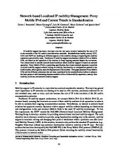
6. MEASUREMENTS AND RESULTS In this section we present the handover delay incurred during the scenario when the MN leaves its home network and enters the domain of another network. The simulation results are then compared with the reference results obtained from a real MIPv6 test-bed.
6.1 Handover Delay Components The MIPv6 handover procedure is composed of several subprocesses and each sub-process incurs its own delay which will contribute to the overall handover delay, and this is expressed as follows: THO = TMD + THR + TRR +TCR Where: THO
= Total Handover Delay
TMD
= Movement Detection Delay
THR
= Home Registration Delay
TRR
= Return Routability Delay
TCR
=Correspondent Registration Delay
The delay incurred due to movement detection (TMD) is furthermore composed of the following delay sub-components: TMD = TL2 + TRD + TDAD Where TL2
= Layer 2 (L2) Handover Delay
TRD
= Router Discovery Delay
TDAD
= Proxy Duplicate Address Detection Delay
The overall handover latency is a sum of the handover latency incurred by L2 handoff process (TL2) and Layer 3 (L3) handoff process (THO -TL2). TL2 is dependent on the WLAN AP and WLAN NIC hardware performance. As demonstrated in [15], there is a large variation in L2 handoff latency for WLAN hardware from different vendors. Since MIPv6 is a L3 mobility management protocol, the handoff delay incurred by this protocol mainly depends on the speed with which the MN is able to detect its movement and discover a new access router. This delay is represented by TRD, and is dependent on the RA interval, the value of which is determined using a uniform distribution function over a minimum and maximum value, whereas the other delay components are more or less constant and they depend on the quality and reliability of the wireless link. For this reason a minimum RA interval value of 0.03 seconds and a maximum RA interval value of 0.07 seconds has been specified in [1]. Since the MIPv6 handoff latency is dependent on TRD, we have chosen three reference values of the RA interval, as depicted in Table 1, to analyze its impact on the overall handoff latency.
6.2 CNI-MIPv6 Test Bed A real Linux based MIPv6 test-bed [16] has been established at the Communication Networks Institute (CNI), Dortmund University of Technology. Due to the infrastructural restraint/limitations of the lab environment and a wide area of coverage (in 100’s of meters) of the WLAN APs, it was not possible to keep the Access Router of the visit network and the HA far apart to effectively realize an actual MIPv6 network infrastructure. Therefore in order to get effective insights into the various delay incurring parameters/factors and to quantify their overall effect on the MIPv6 handover latency, the movement of the MN from home network to visit network was emulated by manually switching the MN to the visit network. This emulated movement of the MN was repeated 10 times for each of the three reference RA intervals depicted in Table 1. Ethereal [17] was used to capture the traffic and custom bash scripts were used to parse the ethereal traffic log and calculate the average delay incurred by each of the delay component. The total average handover delay was then calculated as the sum of all the measured delays. The average delay incurred by individual delay components and the total handover delay is listed in Table 2.
6.3 xMIPv6 Simulation Model Figure 6-1 shows the simulation network topology that is representative of the network topology of the real CNI-MIPv6 test-bed described in section 6-2. This simulation model is based on the xMIPv6 simulation model described in the preceding sections. In the simulation model, the MN’s movement from its home network towards the visit network is repeated 100 times for each of the 25 seed values generated using OMNET++’s sedtool [2], constituting a total of 2500 runs. This is repeated for each of the three reference RA intervals (see Table 1).
Custom bash scripts were used to automate the test process and to parse the scalar files which recorded the time stamps of the parameters of interest.
simulation model is very much similar to that of the CNI-MIPv6 test bed, in that the RA interval mainly affects the delay component TMD, whereas the other MIPv6 protocol specific delay incurring components (THR,, TRR, TCR) are independent of the effect of RA interval, and hence remain constant through all the test runs in both the test bed and simulation model. This is expected as the value of RA interval has a direct impact on the time it takes for the MN to determine whether it has moved to a new network or not, as explained in section 6.1. The value of RA mainly impacts the TRD component of the TMD whereas TDAD remains constant and TL2 depends on the performance and quality of the WLAN hardware. Comparing the results of the real test bed and simulation model, it is seen that there is not much difference in the various delay components except in TMD which is comparatively more pronounced for Test 1 than for the other tests. This can be explained in terms of the large difference between the minimum and maximum RA interval and also the difference in the number of experiments carried out in the two test beds (10 repetitions in real test bed vs. 2500 repetitions in simulation test bed).
Figure 6-1: Reference Simulation Network Topology The total handover delay was then calculated as the average sum of all the measured delays. The average delay incurred by individual delay components and the total handover delay is listed in Table 2.
The other delay components are very much constant owing to strict adherence to the various timing requirements as laid out in the standard and modelling messages based on real message formats and IPv6 addressing schemes.
5,00
Table 1. Minimum and Maximum Values of the RA Interval (in seconds) for the Three Reference Test Runs
Correspondent Registration Delay Return Routability Delay Home Registration Delay Movement Detection Delay
Handover Delay (sec)
4,00
3,00
2,00
1,00
0,00
CNI-MIPv6
xMIPv6 Sim Test 1
CNI-MIPv6
xMIPv6 Sim Test 2
CNI-MIPv6
xMIPv6 Sim Test 3
Test Run
Figure 6-2: Comparison between Various Delay Incurring Components
Handover Delay (sec)
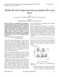
Table 2. Handover Latency Comparison between the Real Test Bed and Simulation Model for the Three Reference Test Runs
CNI-MIPv6 Test Bed
4,50
xMIPv6 Simulation Test Bed
3,50
2,50
1,50
1
2
3
Test Run
6.4 Analysis Table 2 compares the total handover delay measured in both the CNI-MIPv6 test-bed and the xMIPv6 Simulation model and figures 6-2 and 6-3 depicts the results graphically. As depicted in Table 2, it is evident that overall, the operational and functional characteristics and performance of the xMIPv6
Figure 6-3: Handover Delay Comparison
7. CONCLUSION AND FUTURE WORK The test results shows the appreciable accuracy and consistent behaviour of the simulation model in terms of the handover delay as compared to the handover delay measured in the real test bed.
The accuracy of the simulation framework has been ensured by modelling messages based on the actual message formats, carefully selecting and implementing message/event timers and timeouts and by careful and close conformance and strict adherence to the relevant standards. The accuracy of the xMIPv6 simulation model makes it ideal for building other MIPv6 related mobility management protocols with a great degree of confidence in its accuracy. Furthermore the effect of handover delay on higher layer protocols such as TCP and UDP needs to be compared for both the real test bed and simulation model. For the future, features like IP Security and Dynamic Home Agent Address Discovery (DHAAD) are also planned.
8. ACKNOWLEDGMENTS
Request for Comments (Draft Standard) 3963, Internet Engineering Task Force, January 2005 [8] P. Bhagwat, C. Perkins and S. Tripathi, “Network Layer Mobility: An Architecture and Survey”, IEEE Personal Communication , Volume 3, June 1996. [9] Lai, J., Wu, E., Varga, A., Sekercioglu, A. “A Simulation Suite for Accurate Modeling of IPv6 Protocols”, 2nd International OMNeT++ Workshop. January 2002, Berlin, Germany. [10] Wu, E., Lai, J., and Sekercioglu, A. 2004. A Simulation Model of Mobile IPv6 Protocol. Proceedings of the Australian Telecommunications Networks And Applications conference - ATNAC’04 (Dec. 204), Sydney, Australia.
We would like to thank Mr. Alain Tigyo for his assistance in performing simulation measurement tests.
[11] S. Thomson, T. Narten, T. Jinmei, ”IPv6 Stateless Address Autoconfiguration”, Request for Comments (Draft Standard) 4862, September 2007.
9. REFERENCES
[12] R. Droms, et al, “Dynamic Host Configuration Protocol for IPv6 (DHCPv6)”, Request for Comments (Draft Standard) 3315, July 2003.
[1] D. Johnson, C. E. Perkins, and J. Arkko, ``Mobility Support in IPv6'', Request for Comments (Proposed Standard) 3775, Internet Engineering Task Force, June 2004. [2] OMNeT++ Community Site, http://www.omnetpp.org, 31st January 2008. [3]
R. Koodli, “Fast Handovers for Mobile IPv6”, Request for Comments (Draft Standard) 4068, Internet Engineering Task Force, July 2005.
[4] H. Soliman, C. Castellucia, K. El Malki, L. Bellier, “ Hierarchical Mobile IPv6 Mobility Management (HMIPv6)”, Request for Comments (Draft Standard) 4140, Internet Engineering Task Force, August 2005. [5] R. Wakikawa et al., “Multiple Care-of Addresses Registration”, draft-ietf-monami6-multiplecoa-04 (work in progress), November 2007. [6] S. Gundavelli et al., “Proxy Mobile IPv6”, draft-ietf-netlmmproxymip6-07 (work in progress), November 2007. [7] V. Devarapalli, R. Wakikawa, A. Petrescu, P. Thubert, “Network Mobility (NEMO) Basic Support Protocol”,
[13] T. Narten, E. Nordmark, W. Simpson, H. Soliman, “Neighbor Discovery for IP Version 6 (IPv6)”, Request for Comments (Draft Standard) 4861, September 2007. [14] A. Conta, S. Deering, “Generic Packet Tunneling in IPv6 Specification”, Request for Comments (Draft Standard) 2473, December 1998. [15] Arunesh Mishra, Minho Shin, William Arbaugh, “ An Empirical Analysis Of The IEEE 802.11 MAC Layer Handoff Process”, ACM SIGCOMM Computer Communication Review, Volume 33 , April 2003. [16] MIPL Mobile IPv6 for Linux, http://www.mobile-ipv6.org, 31st January 2008. [17] Network protocol analyzer, http://www.ethereal.com, 31st January 2008.