An Agent-Oriented Model of a Dynamic Engineering Design Process Vadim Ermolayev3, Eyck Jentzsch1, Oleg Karsayev2, Natalya Keberle3, Wolf-Ekkehard Matzke1, Vladimir Samoylov2, Richard Sohnius1 1
Cadence Design Systems, GmbH, Feldkirchen, Germany {wolf, jentzsch, rsohnius}@cadence.com 2 SPII RAS, Saint Petersburg, Russia {ok, samovl}@iias.spb.su 3 Zaporozhye National Univ., Zaporozhye, Ukraine
[email protected],
[email protected]
Abstract. One way to make engineering design effective and efficient is to make its processes flexible – i.e. self-adjusting, self-configuring, and selfoptimizing at run time. This chapter presents the descriptive part of the Dynamic Engineering Design Process (DEDP) modeling framework developed in the PSI 1 project. The project aims to build a software tool to assist managers to analyze and enhance the productivity of the DEDPs through process simulations. The framework incorporates the models of teams and actors, tasks and activities as well as design artifacts as the major interrelated parts. DEDPs are modeled as weakly defined flows of tasks and atomic activities which may only “become apparent” at run time because of several presented dynamic factors. The processes are self-formed through the mechanisms of collaboration in the dynamic team of actors. These mechanisms are based on contracting negotiations. DEDP productivity is assessed by the Units of Welfare collected by the multi-agent system which models the design team. The models of the framework are formalized in the family of PSI ontologies.
1 Introduction It is widely accepted that the processes of engineering design differ from manufacturing processes by the fact that they “… are frequently chaotic and nonlinear, and have not been well served by project management or workflow tools” (cf. [1]). The primary reason is that the ability to design is one of the signatures of human intelligence which can hardly be framed by the rigid and static bounds of pre-defined business processes. Therefore, one of the promising ways to make engineering design effective and efficient is to manage its processes in a flexible manner – i.e. make them self-adjusting, self-configuring, and self-optimizing at run time. By doing so we may enhance the degree of coherence among the interrelated activities and make them better coordinated and therefore more productive. Hence, the model of a DEDP 1
Performance Simulation Initiative (PSI) is an R&D project of Cadence Design Systems GmbH.
should be at least capable to account for the constellation of the factors which make a DEDP “chaotic and non-linear” and, at most, to eliminate them as much as possible. Using software agents for optimizing DEDPs at runtime, in dynamics is natural. Indeed, an agent by definition is capable of acting autonomously, pro-actively, and rationally in pursuit of the desired state of affairs. Therefore, it may be used as the locus of self-configuration and self-optimization in a DEDP. Provided that we have built such a fine-grained, agent-oriented DEDP modeling framework, we may implement software tools allowing to assess a process and, ultimately, to optimize DEDPs in terms of engineering design productivity. Improving DEDPs in terms of engineering design productivity is the focus of the PSI project. The project has prototyped a software tool which provides for the assessment of accomplished DEDPs and the prediction of the characteristics of planned DEDPs through their simulation. This simulation prototype has been implemented as a multi-agent system [2] 2 which models: designers’ teams working on projects by dynamically formed teams of software agents; DEDPs performed by these teams by tasks; the results of these processes by design artifacts. The knowledge about the performed processes is formalized and stored to the PSI testbed in terms of the PSI family of ontologies presented in this chapter. Thus, we obtain an incremental collection of the actors’ experience which is further on re-used to make simulation results more reliable. The chapter is structured as follows: Section 2 discusses modeling requirements justifying the necessity to cope with the dynamic character of DEDPs. Section 3 outlines our approach to assessing the productivity of DEDPs. Section 4 presents the ontological model of a DEDP designed as a family of ontologies. Section 5 deals with the epistemological and usage aspects of PSI ontologies. It also briefly reports on the evaluation of the presented ontologies. Section 6 surveys the related work and analyses the contributions of the presented DEDP model. Section 7 concludes the chapter. This chapter is the substantially revised version of our paper [3]. The revision has been undertaken to present the advancement we have achieved in the development of PSI ontologies and is based on their specification version 1.5 [4]. The negotiation part of this framework uses PSI Generic Negotiation Ontology [5].
2 Modeling Principles A DEDP is understood as a weakly defined engineering design workflow. It aims to achieve its goal (the design artifact comprising a certain set of its representations) in an optimal way in the terms of result quality and gained productivity. It is therefore clear that the following entities are involved in the process: actors, who form design teams and collaboratively do the work in the flow; activities, which are the atomic parts of a workflow defined by the technology used in the house; tasks, which are the representations of hierarchical clusters of activities; and design artifacts, which are the results of engineering design activities. Hence, activities are defined by the design 2
In this chapter we omit the description of this important part of our research due to space limitations.
Team
joins
Actor
Mechanism assesses
Actor
Dynamic
commitsTo
Task
dependsOn
Design Artifact
Task
allocates
manages
executes
Task ?
?
…
Subjectively Static
transforms
Activity
Software Resource Tool
… …
Generic Activities
Shared Static
Generic Tasks
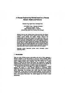
Fig. 1. Static and dynamic components of the modeling framework.
technology and are well known before a DEDP starts. They form the “basket” of activities (Fig. 1), are uniformly understood and used by any actor and, therefore, may be considered generic. Another static shared “basket” is the one of generic tasks – please refer to the description below. Other elements may only “become apparent” at run time because: − A generic activity may be executed only if it is assigned to an actor and is applied to a certain design artifact. Such an activity differs from a generic one by having particular associations to an actor and a design artifact. Task – Activity Ontology contains two separate concepts for a generic activity and an activity. − Tasks are also distinguished as generic and as actually performed in the presented ontologies. A generic task is a shared static template defining a typical transformation of a design artifact from an initial set of representations to the target state. This transformation can be achieved by different combinations of generic activities. A task is subjectively dynamic because of its relationship to the specific actor who performs the task. This relationship is resolved as the result of the task assignment to an actor which happens at run time, when the DEDP is performed. Task – Activity Ontology contains two separate concepts for a generic task and a task. − A task is the model of the emerging hierarchical structure of a DEDP or the part of a DEDP. It may contain tasks and activities as its integral parts. The main purpose of a task is to arrange the assignment of its sub-tasks and activities. This arrangement is done by the actor (having the function of the task manager) who performs the task. The assigned sub-tasks may be consequently arranged in the similar manned by their task managers until the “leaves” of the hierarchical structure (the activities) are reached. These activities are assigned to and executed by the actors. By formalizing the above we define the model of the cascade decomposition of tasks and, ultimately a DEDP at run time. − The number of activity loops is not defined in advance. It depends on the quality checks at intermediate steps. Changing the number of activity loops may cause changes in activity duration. In turn, it may cause delays of the dependent tasks and activities with associated penalties for, e.g., deadline violation.
− The duration of activity execution is not defined in advance. Different actors are able to spend different capacities to execute the same activity at a certain time. Actors may perform the same activity with different efficiencies (productivities – Section 3). An activity may remain idle while waiting until the pre-conditions have been triggered. Idle state duration can’t be computed in advance because the preconditions may be formed by other activities executed by other actors. − An actor is chosen by the task manager when s/he decides to assign the activity. In the PSI framework contracting negotiations are the means of optimally choosing the actors to perform the tasks. For the planning phase it means “optimally” from the point of view of the project manager. The DEDP model incorporates the actor model and the means to arrange actors’ collaboration through peers’ assessment and negotiations. Mentioned factors provide certain degrees of freedom 3 in DEDP planning, replanning, scheduling, re-scheduling, and execution. In PSI a DEDP is never rigidly planned before it starts. The decisions of how to continue its execution are made each time it reaches a certain state in the state space. These decisions are made by the design team members who manage the tasks which continue the process. According to the aforementioned properties of a DEDP, different paths through the state space may be more productive or less. As shown in Fig. 1 a DEDP has components which differ along the dimensions of their variability. The first dimension is the dynamic character ranging from static, i.e. pre-defined for all possible DEDPs, to dynamic, i.e., subjected to changes in a DEDP. Another dimension is the sphere of visibility or commitment. This dimension ranges from shared, i.e., having the same meaning and instances for all DEDP participants, to subjective, i.e. having specific instances for different actors (though in the terms of a common ontology). Static shared DEDP components are generic activities, associated software tools, and resources. The model of a DEDP assumes that the processes are assembled (ultimately) of atomic activities which are the pieces of the design technology used by the company. The technology normally provided by a design support unit often suggests the usage of a specific software tool to perform an activity. The execution of a given activity consumes certain resource instances in given quantities. The model of a design process is based on the following assumptions: A DEDP is initiated by an external influence providing a goal to a certain actor. This goal is subjectively transformed to a task according to the knowledge of this actor. The actor uses his subjective knowledge about sub-tasks and activities to decompose a task. The actor may decide to perform a sub-task or to execute an activity of a decomposed task himself or to hire another actor for a price in Units of Welfare (Section 3) using the available collaboration mechanism (contract net negotiations in PSI). In the latter case the sub-task becomes the goal of another peer-actor who commits to performing the corresponding task by striking the contract deal. Hence, the appearance of actor-task combinations in a DEDP is subjectively dynamic. The mechanism of incorporating new actors to the process and the model of the design team are subjectively dynamic as well, since they depend on the decisions and choices taken at run time by the actors which states change in the process. The rules of 3
It should be noted here that this freedom implies more complications in planning, scheduling and the necessity to deal with a finer grained DEDP model.
encounter of the mentioned mechanism are shared static and provide the horizontal laws for the system [6, 7]. A design artifact is a subjectively dynamic outcome of the process since it is formed out by a subjectively dynamic collaborative team of actors. However, the proposed layering allows reaching this effect through applying shared static atomic activities, though in subjectively dynamic combinations. For an activity a design artifact is both the material input and the result of its execution. The actors who perform a task and initiate collaboration are Task Managers. Their rational goal with respect to the performed task is to choose the next step on the process path as productively as possible. Of course for that an actor needs a sort of productivity assessment model.
3 Assessing Productivity by the Earned Units of Welfare Productivity by its very nature is one of the most important economic metrics and is defined by the ratio of the produced output (value) to the consumed input (value). As such, it is an integral characteristic of any transformation process, e.g. a DEDP. This neo-classical definition of productivity imposes rigid requirements on the process under consideration. The homogeneity of inputs and outputs is the most severe one with respect to engineering design. Known productivity measurement methodologies in engineering design ground themselves on the assessment of design complexity characteristics in the creation of homogeneous input- and output-measures. They do it by applying heuristic weights to compared parameters (e.g., the normalized transistor count 4 in Semiconductor and Electronic Systems (SES) design, FP, KSLOC counts 5 in software design, etc.). But the fundamental problem of this approach is that the complexity characteristics need to be invariant both to the type of a process and to the transformed design artifact. If those characteristics are not invariant, measurement scales tend to lack well-defined units. Consequently the properties of the measurement scale, the labeling of the units, and the interpretation of the values derived are of very limited practical use. Furthermore, in non-deterministic environments such measures are not very reliable, even if proposed. It is therefore important to build a measure which addresses the homogeneity requirement with respect to inputs and outputs and which is invariant to the dynamic characteristics of a process (Section 2). Such a measure may be based on the integral process success indicators like for example the ratio of the Earned Value to the Planned Value or to the Actual Cost at a Sign-off Stage of the process. This implies that productivity of a DEDP may be assessed by the value produced and accumulated by designers in a team. The more value produced by a designer – the more relatively productive s/he is. It is also true in a longer run if several DEDPs are taken into consideration. Hence more productive designers are characterized by the higher volume of accumulated Units of Welfare (UoW). It is assumed in PSI that designers receive incentive which is adequate to their produced value. The characteristic of UoW assets is invariant to all aforementioned dynamic features of an engineering design process. It is a 4
Measuring IC and ASIC Design Productivity. White Paper. Numetrics Management Systems, 5201 Great America Parkway, Suite 320 Santa Clara, CA 95054, 2000 5 FP stands for Functional Point, KSLOC – for kilo lines of source code.
Fig. 2. High-level structure of the family of PSI ontologies.
normalized scalar measure which by its semantics is similar to the notion of Utility which is used in Distributed Rational Decision Making. UoW earning and spending mechanisms in PSI are based on contracting deals stricken in several types of negotiations [7].
4 The Overview of PSI Ontologies If we intend to model an arbitrary process of doing something (for example, a design process) the basic building blocks for such a model would be: a goal – the state of affairs to be reached; an action; an object to apply actions to; a subject who applies actions to objects; an instrument to be used by a subject to execute actions; and an environment in which the process occurs. The structure of the PSI ontologies family reflects this approach (Fig. 2). It comprises five tightly linked major ontologies which in UML representation are grouped in separate packages: the Actor Ontology (a subject), the Project Ontology (an environment), the Task-Activity Ontology (an action), the Software Tool Ontology (an instrument), and the Design Artifact Ontology (a goal and an object). The classes shown within the packages in Fig. 2 identify the major concepts of the respective ontologies. This grouping of course reflects the principles of the modeling approach (Section 2). Indeed, the outline given in Fig. 1 and the high-level picture of the family of PSI ontologies have many features in common. 4.1 Actors, Beliefs, Collaboration, Design Teams Actors are the models of designers who form Design Teams to perform design Projects (Fig. 3 6 ). As the members of a Design Team they have certain Commitments with respect to the Design Team and to the Project under performance. Actors 6
Yellow UML packages in Fig. 3, 4, 5 represent the ontologies which are external to the described one.
Fig. 3. Outline of the PSI Actor ontology.
perform (i.e. manage) Tasks and execute Activities which transform certain Design Artifacts. Actors use Software Tools to execute Activities and have certain Attitudes to these Software Tools. Actors consume Resources to execute Activities. One of the important aspects of the Actor model is the representation of Actor’s Ability to perform Tasks, execute Activities, and perform organizational Roles (like Front-End Designer, Back-End Designer, etc.). With respect to an abstract Generic Activity, a Generic Task, and a Role we are also interested if an Actor is able (and to which extent) to execute the atomic action, or to perform a task or a role. The association concepts of an AbilityWrtActivity, an AbilityWrtTask, and an Ability provide the means for the answers. The Actor ontology also describes Communication Channels which emerge among different Actors who collaboratively work on different parts of the specific Design Artifact. The reason for such collaboration is the peculiarity of the structure of the Design Artifact. Collaboration occurs among the Actors who work on parts of the Design Artifact having common Interfaces. Another kind of collaboration among the members of a Design Team is their coordinated performance of Tasks and execution of Activities. This teamwork is arranged via contracting negotiations. An actor playing the Role of a task manager intends to out-source a Task to one of his or her peers. The following two aspects constrain the set of peer-Actors to the sub-set of the believed performers: a task manager believes that the believed performers are (i) capable to perform the Task and (ii) credible enough to trust the performance of the Task to them. These Beliefs are modeled by the Belief concept of the Actor ontology. Beliefs are the important part of the negotiation mechanisms and are related to the concepts of Negotiation Outcomes and Negotiation Strategies of the Generic Negotiation ontology [5]. The Beliefs of the negotiation participants are updated according to the outcome of the negotiation. Beliefs are used by Actors to adjust their negotiation strategies providing the assessments of the peers’ capabilities and credibility [6]. An Actor becomes the contractor for the negotiated generic task or generic activity in result of such a negotiation. He is the only one of believed performers who receives the negotiated Task (Activity) and commits to performing
(executing) it as a member of the Design Team. A Design Team is the bridge providing the relationship of a DEDP to the Project which is implemented performing this DEDP. 4.2 A Project as the Environment of a DEDP The Project ontology describes the environment of a DEDP: an organizational structure around its performance. This ontology at the high level resembles the traditional project planning perspective which states that a process is performed by a team (of Actors) and has a collection of Resources associated with it. A Process is viewed as a sequence of transformations of the target Design Artifact. These transformations may be viewed as the transitions between the States of a Design Artifact. The objective of each transformation is to develop the increment of a Design Artifact in a certain Representation. The States in this transformation process are therefore characterized by the addition of the certain Design Artifact Representations to the Design Artifact under transformation. In the process of this transformation a Design Artifact receives its incremental “slices” at particular States. One such “slice” bijectively corresponds to one instance of a Design Artifact Representation. Representations are booked to the Project Memory. Please see also Section 4.4. 4.3 Tasks, Activities, co-Execution, and Dependencies The purpose of the Task-Activity ontology (Fig. 4) is to provide the descriptive framework for modeling the emerging dynamic hierarchical structure of a design process. As it was outlined in the description of the modeling approach, only Activities are executed. An Activity is understood as the atomic purposeful action which is applied to a certain Design Artifact and results in its transformation from one State to another State adding a Representation “slice” to it. For example, the RTL 7 -Design Activity uses a Design Artifact in the specification representation and transforms this Design Artifact by adding the RTL representation. However, an Activity applied to different Design Artifacts results in different outcomes. Indeed, the RTL-Design Activity applied to FB1 or to FB2 – instances of a Design Artifact – will have FB1 in the target representation of RTL or FB2 in the target representation of RTL respectively as its outcomes. On the other hand, the same activity, even applied to the same FB1 but executed by different Actors, may require different efforts to be spent to achieve its outcome. That is why the ontology introduces the concept of an Activity assuming its particular association with an Actor and a Design Artifact. A Generic Activity is the more abstract concept which denotes or “shapes-out”, as the relationship name suggests, a purposeful, atomic action. This action is actually the transformation which is configured by the State Pattern of an (intended) Design Artifact. This State Pattern is the template which configures the inputs and outputs of the related Generic Activity. These abstract inputs and outputs may receive physical materialization as the particular instances of a Design Artifact (or its sub-concepts) 7
RTL stands for Register Transfer Level
Fig. 4. Outline of the PSI Task-Activity ontology.
only when the Activity corresponding to the configured Generic Activity is executed. The action specified by the Generic Activity may be performed using a Software Tool – either one specific, or several alternative ones. One more important aspect captured by the context of a Generic Activity is the relationship to co-executed activities. The model provided by the ontology allows specifying that a pair of activities may be executed in an arbitrary sequence or should be executed in parallel. For example, the RTL Debug and RTL Verification activities are to be executed in parallel because executing only one of them makes no sense according to the design technology. This part of the model is used in resolving the decomposition of Generic Tasks to Generic Activities at the Work Breakdown Structure generation phase of project planning. The concept of an Activity refines the concept of a Generic Activity by providing the new knowledge about the assigned Actor and the transformed Design Artifact through its relationships. A Generic Activity in contrast to an Activity is the abstract specification of an atomic action. These atomic actions are executed by Actors as Activities aimed to transform Design Artifacts in source representations into Design Artifacts in target representations. The concepts of a Generic Task and a Task have the similar relationship to each other. A Task is performed (managed) by the certain assigned Actor. However, the semantics of this pair of concepts is different from the ones describing activities. A Task is the concept which (i) describes the dynamic hierarchical nature of a design process; (ii) may contain sub-tasks of lower granularity as its integral parts; (iii) may wrap a single or a set of Activities under the umbrella of the single Actor who is the task manager. A Task refines the concept of an (abstract) Generic Task by being related to an Activity and an Actor. A Generic Task is the abstract template of a composite action (in difference to the atomic abstract action modeled by a Generic
Activity). Tasks may also be viewed as the abstract descriptions of capabilities used to form Roles. The presented Task-Activity model handles the dependencies among Tasks and among Activities assuming that these dependencies are strong [3]. These dependencies are resolved by using the knowledge about the initial and target states of the associated Design Artifacts (Section 4.4). A representation of the Design Artifact reached in a particular state (by the execution of certain Activities) is required by the dependent Activity. This state also triggers the Precondition of the dependent Task if the dependencies among Tasks are analyzed. A Task results in certain Post-Effects. A Post-Effect is the event of reaching the particular state by the processed Design Artifact (DA). A similar model is used for capturing the dependencies among Generic tasks or Generic Activities. The difference is in the semantics of the corresponding concepts. For example, a DAStatePattern does not denote the state(s) of a Design Artifact, but is rather the template used for the configuration of the intended inputs and outputs of a Generic Activity. As described in Section 4.1 Generic Tasks and Generic Activities are used as Negotiation Issues in the negotiations on the assignment of Tasks and Activities to certain Actors. 4.4 Design Artifacts The central concept of the Design Artifact ontology (Fig. 5) is Design Artifact – the goal and the object of a design process. At high level the ontology focuses on the following aspects of this model: (i) a Design Artifact as the object of the transformation process is related to the executed actions – i.e., to the concept of an Activity; (ii) a Design Artifact (more exactly the Functional Block of the topmost level) as the goal of the process is materialized in a Chip 8 – the terminal state of affairs to be achieved; (iii) a Design Artifact as a complex structure comprising different integral parts in different representations may induce collaboration of different Actors by indicating common Interfaces of its integral parts; (iv) the trace of Design Artifact transformations and the related states are recorded into the Project Memory. A Project Memory, therefore, provides a link of a Design Artifact transformation trace to the design process environment. From the point of view of domain grounding the ontology specifies that a Design Artifact comprises the hierarchy of Functional Blocks as the structural elements of designed functionality. Functional Blocks are generally viewed as “gray boxes” with functional subdivision defined by the taxonomy of Design Artifact Types. The toplevel examples of these types are: digital, analog, mixed-signal. The taxonomy of types also configures the Applicability of Generic Tasks and Generic Activities to a
8
Design Artifacts may not be materialized in a Chip in some design processes. For example, a process having the goal to design Soft IP will have a different Design Artifact Representation (GDS2 or NetList) as the terminal one. Such Soft IPs are often released in Libraries for further re-use in different design processes and projects. However, Design Artifacts in Semiconductor and Electronic Systems domain are designed to be sooner (in the current process) or later (in another process) materialized in a Chip.
Fig. 5. Outline of the PSI Design Artifact ontology.
Design Artifact. The reason is that the technology and, therefore, the subsets of applicable tasks and activities are different for different types of design artifacts. The instances of a Functional Block are complemented by the instances of the other subclasses of a Design Artifact – Documentations, TestBenches, and Verification Runsets – the means to document, test, and verify designs according to the provided engineering design technology. Design Artifacts are used as Negotiation Issues in a DEDP. The typical cases are: (i) an Actor looks for a Soft IP to be re-used in his current design and negotiates the terms of usage with the owners if this IP; (ii) a Design Artifact is one of the issues in the multi-issue negotiation on the assignment of a Task to an Actor. 4.5 Software Tools The Software Tool ontology focuses on the description of the two aspects of an instrument used by Actors to execute Activities. The first aspect is the instrument itself. A Software Tool is used by an Actor to execute an Activity. The second aspect is the usefulness of a Software Tool. Different Actors while using the same Software Tool may be somewhat productive. Therefore, Actors may have different Attitudes to a certain Software Tool. Though these subjective attitudes are important they, if analyzed separately, do not provide a reliable judgment. Therefore the average impression provided by a Design Team may be more useful for Evaluation purposes. A Software Tool has these relationships to the concepts of an Actor and a Design Team.
5 PSI Ontologies: Epistemology, Usage, and Evaluation The descriptive part of the DEDP modeling framework has been initially designed as a family of ontologies and coded in a set of UML class diagrams. Further formalization and implementation work has been performed in the way aligned with scenarios of ontology usage identified by Uschold and Jasper [10]. PSI ontologies are used [2] for authoring DEDP logs recorded to the PSI testbed, for specifying the design of the DEDP-PMS simulator software, and as shared ontologies for agent communication at run-time. Ontology usage aspects influenced the choice of the formal languages for coding the ontologies. The ontologies were coded in OWL-DL 9 . This language was chosen because it is one of the de-facto ontology specification standards. The second reason for choosing OWL-DL was that its expressive power is similar to that of the internal mental model specification language (MMSL) of MASDK [11] which has been used for specifying the design and prototyping of PSI prototype – DEDP-PMS. From an epistemological viewpoint the transformation of the PSI ontologies to OWL-DL representation required the change of UML associations to constructs with binary relationships with restrictions. This transformation has been performed manually with the help of the Protégé 3.0 10 ontology editor as described in [4]. DEDP-PMS 11 has been implemented to evaluate the modeling framework, to experiment with several planning and scheduling algorithms, and to assess the feasibility of building a software tool for DEDP optimization using their productivity assessment. Two rounds of evaluation experiments have been performed. The 1-st round has been done over the two simplified test cases (the DEDPs for the Digital and the Analog DAs) and used version 1.0 of the PSI family of ontologies. The second round used version 1.4 of the PSI family of ontologies and has been applied to a real world case study [8]. In the 1-st round of evaluation experiments [2] the simulator has been used in two application modes: playback and predictive simulation. In playback mode the simulation is used to assess the performance of DEDPs which have been accomplished in the past. The purpose of the predictive simulation is to support project managers in planning and dynamic re-planning of running design projects in the cases the occurrence of several kinds of events which are out of their control: late changes to the design objective, sudden unavailability of team members, changes in the workload of the designers according to the influence of other independent projects, etc. In the 1-st round of evaluation experiments only the availability of the actors has been altered by random “screwing” of the corresponding simulation parameters. The 2-nd round has been focused on the evaluation of the dynamic planning capabilities. The goal of the experiments was to compare the Work Breakdown Structure automatically generated by the DEDP-PMS with the one created manually by the project manager. The details of these experiments are described in [8].
9
OWL Web Ontology Language Reference. http://www.w3.org/TR/owl-ref/ Protégé ontology editor and knowledge acquisition system http://protege.stanford.edu/ 11 DEDP-PMS has been presented at the 17th European Conference on Artificial Intelligence, ECAI 2006 [27]. 10
Evaluation experiments with the available DEDP records stored to the PSI testbed demonstrated that the simulator develops DEDP plans very closely to what happened in reality – i.e. the plans developed by human project managers. Observed fluctuations were caused by the changes in the parameters of the availability of team members in the course of the simulation experiments by “screwing” their available capacities. This fact confirms the adequacy of the developed framework to the industrial requirements in Semiconductor and Electronic Systems Domain.
6 Related Work and Discussion The projects which pioneered R&D in agent-based engineering design process modeling, support and automation appeared about a decade ago, e.g. [12, 13, 14]. Some projects of the “second wave” [15, 16] helped to specify the focus of PSI in automating the near-optimal arrangement of DEDPs in terms of their productivity. In difference to e.g. [26] the objective of PSI is not to automate the design process itself, but to automate the arrangement of its activities in the most productive way. In PSI the activities resulting in the elaboration of design artifacts are performed manually by human designers. DEDP modeling framework in its part of organizational and actor-related knowledge representation is based on the frameworks [17, 18, 5, 9]. PSI contribution in this part is the incorporation of roles and actors, teams of actors, negotiation context in one coherent family of ontologies and the binding of these ontologies to the engineering design domain by incorporating Design Artifact and Software Tool ontologies. The main contribution of the PSI family of ontologies is the model of a dynamic team of designers which is formed through contracting negotiations and performs dynamically orchestrated processes. Hence, DEDPs in PSI are understood as socially performed processes in the sense close to [19]. For example the notion of a Role of PSI Actor ontology is semantically close to that of the normative multi-agent framework. In the part of process modeling, PSI bases its approach on [20, 6, 21]. In the family of PSI ontologies engineering design processes are modeled as tasks composed of sub-tasks and atomic activities. Similarly to [22] subtasks and activities may have strong dependencies. However, in PSI the knowledge about these dependencies is presented in a different way. The means for that are DA State Patterns and Execution Relations. DA State Patterns are the patterns of DA States. These are the concepts to configure the inputs, the outputs, and the dependencies caused by the usage of the outputs as inputs. By that the dependencies among activities are also aligned with the corresponding DA States. Execution Relations are used to represent concurrency among the activities in a pair. This concurrency may be caused by the specifics of the DA structure. Similarly to [21] tasks have pre-conditions and post-effects. However, the Task-Activity ontology constrains the semantics of pre-conditions and post-effects by making them sub-classes of an event concept. Material inputs and outputs [3] are modeled in frame of DA States. Examples of theoretical frameworks for solving planning tasks are Decision Theoretic Planning (DTP) [23] and Hierarchical Task Networks (HTN) [24]. The PSI framework is built upon the conceptual denotation of the planning task shared by the
mentioned frameworks. Planning is understood as the process of cascade decomposition of the goal, transformation of the sub-goals to Generic Tasks, Generic Activities and committing Actors to Tasks and Activities. However, the PSI framework extends the capabilities of the classical AI approaches to planning by accounting the dynamic character of the process and by the capability to collaborative distributed planning through negotiation mechanisms. The latter feature also distinguishes our descriptive framework from the plan-task ontology of KMI [25]. Moreover, the family of PSI ontologies provides conceptual means for dynamic rescheduling based on the concepts of self-beliefs and beliefs.
7 Conclusions The chapter presented the descriptive part of the DEDP modeling framework developed in the PSI project. The project is aimed to build a software tool assisting in analysis and optimization of DEDPs’ productivity through agent-based simulations. The framework incorporates the models of projects, teams and actors, tasks and activities, design artifacts, and software tools as the major interrelated parts. DEDPs are modeled as weakly defined flows of tasks and atomic activities. These flows are transformation processes. They transform design artifacts passing through the sequence of their states. DEDPs may “become apparent” only at run time because of several factors which are beyond the control of the design team members. The processes are self-formed through the mechanisms of collaboration in the dynamic team of actors. These mechanisms are based on several types of negotiations. DEDP productivity is assessed by the Units of Welfare collected by the multi-agent system which models the design team. The models of the framework are formalized in the family of PSI ontologies. These ontologies are used in the implemented simulator software prototype. Evaluation experiments have been performed using the PSI testbed [2, 8]. These experiments showed that DEDP planning performed using the DEDP-PMS software prototype reflects the reality. Generated DEDP plans are very close to that developed by human project managers.
References 1. Neal, D., Smith, H. and Butler, D.: The evolution of business processes from description to data to smart executable code – is this the future of systems integration and collaborative commerce? Research Services Journal: March 2001, 39-49 2. Gorodetsky, V., Ermolayev, V., Matzke, W.-E., Jentzsch, E., Karsayev, O., Keberle, N., and Samoylov, V.: Agent-Based Framework for Simulation and Support of Dynamic Engineering Design Processes in PSI. In: Pechouchek, M., Petta, P., Varga, L. Z. (Eds.) Proc. 4th Int. Central and Eastern European Conf. on Multi-Agent Systems (CEEMAS'05), 15-17 September 2005, Budapest, Hungary, LNAI Vol. 3690, 511-520, 2005 3. Ermolayev, V., Jentzsch, E., Karsayev, O., Keberle, N., Matzke, W.-E., and Samoylov, V.: Modeling Dynamic Engineering Design Processes in PSI. In: J. Akoka et al. (Eds.): ER Workshops 2005, Proc. 7th Int. Bi-Conference Workshop on Agent-Oriented Information Systems (AOIS-2005), Klagenfurt, Austria, Oct. 24-28, LNCS Vol. 3770, 119–130, 2005
4. Ermolayev, V., Jentzsch, E., Keberle, N., Samoylov, V., and Sohnius, R.: The Family of PSI Ontologies V.1.5. Reference Specification. Technical Report PSI-ONTO-TR-2006-2, 14.04.2006, Cadence Design Systems, GmbH, 56 p. 5. Ermolayev, V. and Keberle, N.: A Generic Ontology of Rational Negotiation. In: Karagiannis, D., Mayr, H.C. (Eds.): Information Systems Technology and its Applications. 5-th Int. Conf. ISTA'2006, May 30 – 31, 2006, Klagenfurt, Austria, 51-66, 2006 6. Ermolayev, V., Keberle, N., Kononenko, O., Plaksin, S., and Terziyan, V.: Towards a framework for agent-enabled semantic web service composition. Int. J. of Web Services Research, 1(3): 63-87, 2004. 7. Ermolayev, V., Jentzsch, E., Matzke, W.-E., Schmidt, J., Schroeder, G., Weber, S., and Werner, J.: Agent-Based Dynamic Engineering Design Process Modeling Framework. Technical Report. Cadence Design Systems, GmbH, 29 p., 2004, 8. Sohnius, R., Ermolayev, V., Jentzsch, E., Keberle, N., Matzke, W.-E., and Samoylov, V.: Managing Concurrent Engineering Design Processes and Associated Knowledge. To appear In: Proc 13th ISPE Int. Conf. on Concurrent Engineering: Research and Applications, Sept. 18-22, Les Antibes, France, available at: http://ermolayev.com/eva_personal/evapubs.htm 9. Ermolayev, V. Keberle, N. and Tolok, V.: OIL Ontologies for Collaborative Task Performance in Coalitions of Self-Interested Actors. In: H. Arisawa, Y. et al (Eds.): Conceptual Modeling for New Information Systems Technologies ER 2001 Workshops, Yokohama Japan, November 27-30, 2001. LNCS vol. 2465, 390-402, 2002. 10. Uschold, M. and Jasper, R.: A Framework for Understanding and Classifying Ontology Applications. In: 12-th Workshop on Knowledge Acquisition, Modeling and Management (KAW’99), Banff, Alberta, CA, 16-21 Oct., 1999 11. Gorodetski, V., Karsaev, O., Samoilov, V., Konushy, V., Mankov, E., and Malyshev, A.: Multi Agent System Development Kit: MAS software tool implementing GAIA Methodology. In: Z. Shi and Q. He (eds.) Int. Conf. on Intelligent Information Processing (IIP2004), Beijing, Springer, 69-78. 2004. 12. Cutkosky, M.R., Englemore, R.S., Fikes, R.E. Genesereth, M.R. Gruber, T.R., Mark, W.S., Tenenbaum,J.M., and Weber, J.C.: PACT: An Experiment in Integrating Concurrent Engineering Systems. IEEE Computer 26(1), 28-38, 1993 13. Darr, T. P. and Birmingham, W. P.: An Attribute-Space Representation and Algorithm for Concurrent Engineering. CSE-TR-221-94, University of Michigan, Department of Electrical Engineering and Computer Science, Ann Arbor, Michigan 48109-2122, 1994. 14. Balasubramanian, S. and Norrie, D. H.: A Multi-Agent Intelligent Design System Integrating Manufacturing and Shop-Floor Control. In: Proc. First Int. Conf. on MultiAgent Syst., San Francisco, 3-9, 1995 15. Parunak, H.V.D., Ward, A.C., Fleischer, M., and Sauter, J. A.: The RAPPID Project: Symbiosis between Industrial Requirements and MAS Research. Autonomous Agents and Multi-Agent Systems 2: 111-140, 1999. 16. Danesh, M. R. and Jin, Y.: An Agent-Based Decision Network for Concurrent Engineering Design. CERA 9(1), 37-47, 2001. 17. Fox, M.C. and Gruninger, M.: Enterprise Modelling. AI Magazine 19(3): 109–121, 1998. 18. Uschold, M. King, M., Moralee, S., and Zorgios, Y.: The Enterprise Ontology. Knowledge Engineering Review, 13(1), 1998
19. Boella, G. and van der Torre, L.: An Agent Oriented Ontology of Social Reality. In: Varzi, A., Vieu, L. (Eds.) Proc. 3-d Int. Conf on Formal Ontology in Information Systems (FOIS’04), Turin, Nov. 3-6, 199-209, 2004 20. Buhler, P. and Vidal, J.M.: Enacting BPEL4WS Specified Workflows with Multiagent Systems. In: Proc. of the Workshop on Web Services and Agent-Based Engineering, 2004 21. Fensel, D. and Bussler, C.: The Web Service Modeling Framework WSMF. Electronic Commerce Research and Applications 1(2): 113-137, 2002. 22. Nagendra Prasad, M. V., and Lesser, V. R.: Learning Situation-Specific Coordination in Cooperative Multi-Agent Systems. Autonomous Agents and Multi-Agent Systems. 2(2): 173-207, 1999 23. Blythe, J.: Decision-Theoretic Planning. AI Magazine, 20 (2), 1999. 24. Erol, K., Hendler, J. and Nau, D. S.: Semantics for Hierarchical Task-Network Planning. Technical report CS-TR-3239, University of Maryland at College Park, 1994. 25. Rajpathak, D. and Motta, E.: An Ontological Formalization of the Planning Task. In: Varzi, A., Vieu, L. (Eds.) Proc. 3-d Int. Conf. on Formal Ontology in Information Systems (FOIS’04), Turin, Nov. 3-6, 2004. 26. Capera, D., Picard, G., and Gleizes, M.-P.: Applying ADELFE Methodology to a Mechanism Design Problem. In: Proc. 3-d Int. Joint Conf. AAMAS'04, 1508-1509, 2004 27. Samoylov, V., Gorodetsky, V., Ermolayev, V., Jentzsch, E., Karsayev, O., Keberle, N., Matzke, W.-E., and Sohinus, R.: Agent-based Prototype of the Dynamic Engineering Design Process Performance Management System (DEDP-PMS). Presentation at ECAI 2006, Riva del Garda, Italy, Aug 28 – Sept 1, 2006. Abstract is available from: http://ermolayev.com/eva_personal/evapubs.htm