Model-Driven Process Engineering Erwan Breton Société Soft-Maint 4, rue du Château de l'Eraudière, BP 588 44074 Nantes cedex 3, France
[email protected] Abstract Within the domain of information systems, one of the main technological moves we may presently observe in industrial circles is the paradigm shift from object composition to model transformation. This is happening at a very fast pace. Among the concrete signs of this evolution one may mention the ongoing change at the Object Management Group from OMA (Object Management Architecture) to MDA (Model-Driven Architecture). A new information system landscape is emerging that will be more model-centered than objectoriented. Within this context, the information engineer will use and produce many models of low granularity and high abstraction. These models may describe static or dynamic aspects and may be accordingly qualified of product and process models. This paper focuses more particularly on the recent evolution of process models. It shows some aspects of the industrial state of the art in the domain and suggests some benefits that could be reaped from a well-mastered utilization of these techniques.
1. Introduction The diversity of technological solutions is always increasing. In order to deal with this situation, there are basically two approaches. One consists in working with only one solution provider and to hope that this provider will always deliver what we need at a reasonable market cost. The provider could base a complete family of solutions on a given operating system (e.g. Windows) or on a given programming language (e.g. Java) for example. The second solution consists in accepting the diversity of technological solutions as a fact and finding generic solutions to this heterogeneity problem. The Object Management Group has championed this method based on a permanent quest for interoperability. In the early years of OMG, the problem was code interoperability when it became clear that it was more difficult to make two object-oriented applications (e.g. written in C++ and Smalltalk) work together than two procedure-based applications (e.g. applications written in Pascal and C). In order to solve this challenge, the CORBA software bus
Jean Bézivin LRSG, University of Nantes, 2, rue de la Houssinière, BP 92208 44322 Nantes cedex 3, France
[email protected] and the IDL language had to be defined and to each language was associated a corresponding mapping. More than ten years after, the basic problem of interoperability has to be solved again, in different contexts, with different tools. Instead of dealing with executable programs, we face a variety of active and passive information models. The MOF [4] (Meta-Object Facility), which was adopted by the OMG in 1997, allows managing this increasing diversity. It aims at providing a common formalism for expressing and integrating metamodels. It may thus be considered as a knowledge bus as it defines a framework for model interoperability. The new MDA OMG scheme [10] (Model-Driven Architecture) gives a central role to models and metamodels. Taking into account the various aspects of information system engineering can only be achieved through the well-organized management of a complex lattice of related models. The emerging tendency is to separate business knowledge expression from implementation. The invariants of a business domain may be held apart from the execution code, preserving them from technology evolution. The information of a complex enterprise system originates from various sources (system engineers, managers, software engineers, quality engineers, etc). All the corresponding facets may be expressed using their own specific semantics. As these models share common concerns, they will also have to be bridged together. As a consequence, we need some tools allowing the expression of dedicated formalism (aspect separation) as well as their interconnections (aspect weaving). Meta-modeling technology may allow addressing these issues in a very effective way. These emerging technologies have already strongly impacted software development methods by allowing separation and weaving of business- and platform-specific concerns, model transformation and code generation. Our work is intended to investigate their applicability to process engineering. It encompasses the organization of process meta-models, their relationships with other metamodels (components, organizational structure, etc.) and mechanisms for producing executable platform-specific workflows from generic business processes.
This paper discusses process engineering using the new meta-modeling techniques. We discuss in section 2 the various types of processes, and how this variety could be dealt with. In section 3 we attempt to sketch out a classification of the various meta-models used in the general field of information technology. We are then in position to study their interdependencies. We focus more particularly on the binding between process and component models. Building on this, we show the practical interest and the industrial applicability of this vision in section 4. General considerations on present possibilities and limits of the approach are summarized in the conclusion.
process, a software maintenance process, or a software migration process. All theses sub-types of software process address the same domain but have very specific issues, e.g. the concept of conversion rules from the source environment to the target environment in a software migration process. Finally, the distinction between process types may sometimes appear to be quite illusive. For example, an outsourced maintenance process is both a business process and a software process. The business process defines the communications between the client and the maintainer. The software process specifies how the maintainer performs the maintenance.
2. Process Meta-Models
2.2. Process meta-models architecture
2.1. Various types of processes A process basically defines a set of work items, scheduled according to constraints, which all participate in fulfilling a common purpose. This simple definition may then be enriched to add concepts like data, artifacts, resources, etc. These extensions to the core are contextual to the specific target domain. Examples of process types are: • Manufacturing processes manages the production of materials. PSL [8] (Process Specification Language) addresses this domain. • Business process monitors business applications, e.g. financial, banking or administrative processes. PSL also addresses this domain. ARIS [9] is an industrial business process meta-model. • Software process focuses on software engineering. SPEM [2] (Software Process Engineering Metamodel) is a proposal for such a meta-model in response to the OMG RFP for software process engineering [5]. • Workflows define processes to be enacted by a workflow engine to control the performance of a real process. WfMC [13] (Workflow Management Coalition) defines such a metamodel. A RFP has been submitted by the OMG on this subject [7]. • EAI defines batch processes controlling the routing of data between applications. • etc. All these domains have specific needs. As the purpose of a workflow is to be executed, it is natural for a workflow meta-model to focus on the integration of legacy system applications, i.e. communication protocols, parameters, etc. On the other hand a software process meta-model must include specific concepts such as iterations or milestones. These processes families may still be refined. For example a software process may be a software building
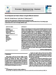
There are many separate process domains. This implies many distinct meta-models. However there exist some core similarities. A process skeleton is a set of ordered activities (or tasks), grouped in order to achieve common global objectives. It may thus be interesting to propose a process meta-model architecture, allowing a specific process meta-model to be defined using a more general process meta-model. Expected benefits are reuse and facilities for process models translation from one metamodel to another. Figure 1 proposes such an architecture based on domain identification and hierarchy. A generic process meta-model may introduce common concepts like activities, objectives, and transitions. More specific metamodels specialize this root meta-model (or a specific one) by adding new relations and entities. Manufacturing metamodel may thus define mechanisms to handle resources consumption, whereas software process may introduce iteration for example. Generic Process
Workflow
Software Buiding Process
Software Process
Manufacturing
Software Maintenance Process
Busines s Process
Software Migration Process
Figure 1: An architecture of process metamodels based on domain identification This quite simple architecture may be compared to the PIF [3] (Process Interchange Format) mechanism of partial shared views, allowing the generic PIF core metamodel to be extended for addressing domain-specific
needs. PSL proposes another similar architecture. General mechanisms (for real-time, resource consumption, etc.) are defined in separate packages and may be assembled into domain-centric meta-models. These two approaches may be used within the same framework, allowing defining generic patterns, to reuse them to define domainrelated meta-models, and to extend these latter ones for addressing more specific needs.
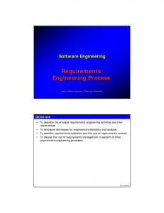
3. Organization of Meta-Models 3.1. Meta-models architecture A meta-model defines a language for describing a specific domain of interest. For example UML [6] (Unified Modeling Language) describes the artifacts of an object-oriented software system. Some other meta-models address domains like process, organization, quality of service, etc. Their number may be very important as identified domains are highly specialized. In this way they allow separating the aspects of a system. Although they are first defined as separate components, it is obvious that many relationships exist between them. Thus they are organized in network allowing the definition of more high-level domains. For example an enterprise may be defined as a lattice of interdependent meta-models. Figure 2 is typical of this organization. Objectiv es
Products
Organization
products of software processes, and which will be used as applications by the agents who perform business processes. There are two broad families of models: product and processes. A product model may describe for example the software artifacts one may find in an object-oriented design; these artifacts may be specified with one of the nine basic diagrams of the UML formalism. Another example of a product model would be the QoS attributes associated with the functional attributes of a similar system. Corresponding process models could be the software process intended to produce the design model or the QoS model as well as the software process intended to produce the designed application conforming to the QoS model.
3.2. Relations between meta-models In Figure 2 we describe an enterprise as a lattice of meta-models, each meta-model defining a particular domain of interest. However, even if they are separately defined, many interdependencies exist between them. The first obvious kind concerns the associations that stand between concepts defined in different meta-models. For example we may want to specify that a business process activity can create an object. This implies that the Create association has been defined between the Activity concept from the business process meta-model and the UML Class concept. This association may be introduced in the following way (Figure 3). A Relation meta-model is created, which imports both UML and the Process metamodel. It contains the Create association, which links the Activity and the UML Class. This is made possible since every meta-model is based on the MOF. Both Activity and UML Class are MOF Classes and they may therefore be linked by MOF References.
Processes
MOF basedOn Applications
Class
Reference
basedOn
Costs
instanceOf
Figure 2: A possible lattice of meta-models defining an enterprise An enterprise has some objectives, which may be achieved by products or processes. Products are the inputs and outputs for processes. Human or software agents within the organization perform processes. Processes may be of different types and generate costs. For example a bank is concerned with such business processes as cash retrieval or account opening. The software development team of a bank performs software processes. This team produces software components which are the result
instanceOf UML
Process MM basedOn Activity
Class
imports
Relation MM
imports
Create
Figure 3: The creation association between the UML Class and the Activity
The second kind concerns the structural mappings between models. Two elements (or set of elements) of different models may represent the same concept at different level of abstraction or from different viewpoints. For example there are many dependencies between the UML design model and the Java model of a software component. Such dependencies may also exist between a generic business process model and the workflow model that implements it. Moreover these mapping dependencies may stand between concepts from separate domains. For example, we may define in a process model an activity which is performed by an agent and which is supported by a to-do application. The agent will therefore have to interact with this application in order to achieve whole or a part of the operations of the activity. When modeling this application in UML, we must take this situation into account. This could be achieved by defining a use-case corresponding to this activity (see Figure 4). There are thus some dependencies between the process application and the UML model, the activity and the use case and the agents. Process
issues. Second, when building the model, he will have to interface it with already existing models such as organization, components, etc. Finally, having defined the modeling environment, he will have to specify its mapping to the execution environment. Still currently, models are mostly used as an information support for the code-writer. Tomorrow, and it is an objective of the MDA, they will be totally integrated in the engineering chain. More and more operations will be done at the model level. Generation services will be defined to produce (completely or partly) workflow models, business information system, the monitoring system and the binding between all these systems. The following example presents a sample of what could be expected from the MDA and other similar technologies. In Figure 5 we have defined a simple process model. It is composed of an activity performed by a procedural role. A software component may be invoked during the execution of the activity. The role is played by an organizational unit (a group or a person). The process meta-model must thus be connected to other meta-models such as an organization or a component meta-model.
Application (UML)
Organization Model anActivity
mapping
anAgent anApplication
Process Model
Component Model
Structural
anAgent
Use Case anActivity
Figure 4: An example of structural mapping between models from separate domains We face thus a set of meta-models, which covers separate domains. Each meta-model may be specialized by another meta-model to address more specific needs, e.g. there is an UML extension dedicated to real-time specificities, and another. A single domain may be described by various meta-models, which may have different abstraction levels. Meta-models may be related, either by direct extension, or by a specific mapping metamodel which defines associations between entities from these initially separate meta-models. Finally there also exist some structural mappings between meta-models, which may guide the way they are engineered.
4. Industrial Applicability and Assessment 4.1. Usage scenario From what have been said in the former paragraphs we may induce the way a process engineer will accomplish its job in the future. First, he will have to choose the right process meta-model to express the process model. This choice may depend upon the domain in consideration, contextual needs or his own habits. He may also decide to extend an existing standard model to address specific
Group anActivity Domain
Person
aComponent
aRole
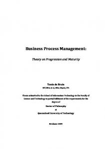
Figure 5: A particular modeling environment In Figure 6 we have defined such an architecture. An activity may invoke a component using parameters. A role may be assigned to an organizational entity. This assignment may be constrained by a condition that which holds on the Organizational Entity. For example, we may assign a role to the hierarchical responsible of the person who performs the preceding activity. Organization MM
Process MM
Organizational Entity
Role
Component MM
performer Activity performs
assignee
Component invoked
Relation MM Role Assignment constraint
ToolInvocation parameters
Figure 6: Relations between meta-models
The architecture presented Figure 6 defines the modeling environment. It establishes how may be described a process. It therefore drives the way the execution environment is implemented. Some mapping mechanisms must be defined between both environments. Figure 7 shows some samples of what could be generated from the modeling environment. The process model is mapped to a workflow. The inter-model relations are mapped to inter-application relations. The assignment of the role to a specific person is translated into a LDAP request, and the invocation of a component is replaced by a CORBA request. Organization Model
Process Model
Definition and Organization Definition) and the fifth one (Integration Definition) defines their inter-relations (see Figure 8). Application Definition
Process Definition
Organization Definition
Component Model
Integration Definition
Group anActivity Domain
Person
Generation of the LDAP request LDAP
aComponent
aRole
Figure 8: Meta-models modular architecture
Generation of the workflow Workflow
Generation of the CORBA request CORBA
Root anActivity
Group Person
Product Definition
A CORBA Component
aRole
Figure 7: Mapping the modeling environment to a particular platform The same model could be mapped to another execution environment. The workflow management system (WfMS) could be different, the organization could be stored in a database instead of a LDAP directory or the components could be EJBs (Enterprise Java Beans) instead of CORBA components. These changes in the execution environment do not have any impact on the model. The deep invariants of the enterprise are thus preserved.
The Integration Definition package defines the assignments of roles to organizational units (i.e. persons or groups of persons), the products (i.e. document files, programs or models) that may be manipulated (i.e. referred, updated or created) and the applications that may be used during the execution of a task. OrgUnit
Product
(from Organi zation Defi ni ti on)
(from Product Defini tion)
+isPlayedBy Role (from Process Definition)
+manipulate
+performs +performer
Task (from Process Definition)
+invoke Application (from Appl ication Defi niti on)
4.2. A first industrial application Such an approach has already been (at least partly) experimented by Soft-Maint for an outsourced maintenance project (a more precise presentation of this project has been done in [1]). A specific meta-model has been developed that fits the needs of expression of the business experts. This meta-model allows describing (sometimes in a simplistic manner) processes, applications, products and the organizational structure. A process is defined as a set of tasks (the atomic work item) and activities (a set of tasks). Their execution is constrained by transitions. The meta-model is organized in five packages. Four packages are defined independently (Process Definition, Application Definition, Product
Figure 9: The Integration Definition package Based on this formalism an application has been developed for capturing graphically process models [12]. Once a model has been defined some outputs may be produced using Scriptor, a code generator. Scriptor was first dedicated to produce pieces of code (Java, C++, Smalltalk, etc.) from UML models [11]. It allows attaching some generation rules (written in Java) to every element of a meta-model. These rules may then be applied to a particular model. We have developed a particular version of Scriptor, specific to our process meta-model. In this way we may exploit models based on this formalism for generating inputs for WfMS (successful tries have
already been made with three different ones) and interfaces with the users and the execution environment (see Figure 10). Process model
Scriptor Generation rules Workflow model Workflow interfaces
Figure 10: From the modeling environment to the execution one In this way the business experts define their process in a formalism they are used to. They do not have to take in account the particularities of the workflow management system for supporting the execution of the process. The mapping between the modeling and the execution environments is made through the generation rules. Some patterns may be defined for translating modeling constructs that do not exist in the execution environment or for addressing specific needs in a transparent way, i.e. without "polluting" the model. During a project both the model and the generation rules may evolve. The metamodel itself may be updated by the means of lightweight extensions (using stereotypes and tagged values) or heavyweight ones (i.e. the definition of additional elements within the meta-model). The execution environment artifacts are not directly updated, but they are re-generated from the model. They are therefore kept consistent with their specifications.
5. Conclusions We have discussed in this paper some aspects of the organization of processes and their relations to other meta-models. The MOF framework allows these metamodels to be explicitly and precisely defined. In this way they may be manipulated, i.e. extended for specific needs or for integrating external concepts. The move from implicit to explicit is characteristic of model engineering. Explicit model representations added to enterprise repository solutions allow to understand more clearly the relations existing between all items of concern to the enterprises and their information systems. The ultimate goal is not however to simply contemplate the different pieces of the jigsaw but to be in a position to build operational bridges and to implement executable solutions. Models are therefore no more used only as mere
documentation for programmers, but they can be directly used to drive tools. This is what we have presented in the last section. The transition from code-centric architecture (like the OMG’s OMA) to model-centric architecture (like the OMG’s MDA) has many impacts on process engineering. First, explicit meta-models allow engineers to choose the formalism, which suits best their needs of expression. If the chosen meta-model does not address every specific issue it may be adapted by using extension mechanisms. Second, the integration of a process in its execution environment is no more done at the execution environment level but at the modeling environment level. Integration is thus much easier and is preserved from technology changes. And last but not least, the transition from modeling environment to execution environment is at least partly automated. The modeling environment groups a set of meta-models that defines a network. This network may then be used to produce implementationlevel artifacts.
6. References [1] Breton E., Ouertal M., Bouchet J.P., "Executing process models using a workflow engine", ICSSEA'2000, Paris, December 2000. [2] IBM, Rational Software, Fujitsu/DMR, SOFTEAM, Unisys, Nihon Unisys Ltd., Alcatel, Q-Labs "The Software Process Engineering Management (SPEM) Revised Submission", OMG Document ad/2001-03-08, April 2001. [3] Lee J., Grunninger M., Jin Y., Malone T., Tate A., Yost G. & other members of the PIF Working Group "The PIF Process Interchange Format and Framework Version 1.2", The Knowledge Engineering Review, Vol. 13, No. 1, pp. 91-120, Cambridge University Press, March 1998. [4] OMG, "Meta Object Facility (MOF) Specification.", OMG Document ad/97-08-14, September 1997. [5] OMG, "Software Process Engineering Request for Proposal.", OMG Document ad/99-11-04, November 1999. [6] OMG, "OMG Unified Modeling Language Specification version 1.3", OMG Document ad/99-06-08, June 1999. [7] OMG, "UML Extensions for Workflow Process Definition Request For Proposal", OMG Document bom/2000-12-11, December 2000. [8] Schlenoff C., Knutilla A., Ray S., "A Robust Process Ontology for Manufacturing Systems Integration", Proceedings of 2nd International Conference on Engineering Design and Automation, Maui, Hawaii, August 1998. [9] Scheer A.-W. ARIS – Business Process Frameworks, Springer, 1998. [10] Soley R. and the OMG Staff Strategy Group, "Model Driven Architecture", November 2000. [11] Soft-Maint, "Scriptor 2.3 Manuel de l'utilisateur", technical document, 2001. [12] Soft-Maint, "Workflow Builder 2.4 Manuel de l'utilisateur", technical document, 2001. [13] Workflow Management Coalition, "Interface 1: Process Definition Interchange, Process Model", http://www.aiim.org/wfmc/, 1998.