MDA framework [10] provides an approach for specifying systems indepen- ... Executable UML [19] means an execution semantics for a subset of actions.
STUDIA UNIV. BABES ¸ –BOLYAI, INFORMATICA, Volume LII, Number 2, 2007
AN AGILE MDA APPROACH FOR EXECUTABLE UML STRUCTURED ACTIVITIES ˘ ˆ ˘ I. LAZAR, B. PARV, S. MOTOGNA, I.-G. CZIBULA, AND C.-L. LAZAR Abstract. Agile processes allow developers to construct, run and test executable models in short, incremental, iterative cycles. However, the agile development processes tend to minimize the modeling phase and the usage of UML models, because UML is a “unified” (too general) language with a lot of semantic variation points. The current version of UML together with its Action Semantics provide the foundation for building object-oriented executable models. But, constructing executable models using the existing tools and the current standard notations is a tedious task or an impossible one because of the UML semantic variation points. Agile MDA processes try to apply agile principles in the context of executable models. This paper presents a procedural action language for UML structured activities that allows developers to apply agile principles for executable models that contains structured activities. New graphical notations for structured activities are also introduced for rapid creation of tests and procedures.
1. Introduction UML 2 [16] is the de-facto standard for modeling software systems. However, most commonly, UML models are used as blueprints that are fill in with code, and the current agile development processes (e.g. agile model-driven development [2], test-driven development [3]) tend to minimize the modeling phase and the usage of UML models. MDA framework [10] provides an approach for specifying systems independently of a particular platform and for transforming the system specification into one for a particular platform. But development processes based on MDA are not widely used today because they are viewed as heavy-weight processes - they cannot deliver (incrementally) small slices of code as soon as possible. Received by the editors: November 19, 2007. 2000 Mathematics Subject Classification. 68N15, 68N30. 1998 CR Categories and Descriptors. D.2.2 [Software Engineering]: Design Tools and Techniques – Computer-aided software engineering, Flow charts, Object-oriented design methods; D.2.4 [Software Engineering]: Software/Program Verification – Programming by contract, Assertion checkers; D.2.5 [Software Engineering]: Testing and Debugging – Debugging aids, Testing tools; 101
102
˘ ˆ ˘ I. LAZAR, B. PARV, S. MOTOGNA, I.-G. CZIBULA, AND C.-L. LAZAR
In this context, executing UML models became a necessity for development processes based on extensive modeling. For such processes models must act just like code [18]. UML 2 and its Action Semantics [16] provide the foundation to construct executable models. In order to make a model executable, the model must contain a complete and precise behavior description. But, creating a model that have a complete and precise behavior description is a tedious task or an impossible one because of many UML semantic variation points. Executable UML [19] means an execution semantics for a subset of actions sufficient for computational completeness. Two basic elements are required for such subsets: an action language and an operational semantics. The action language specifies the elements that can be used and the operational semantics establishes how the elements can be placed in a model, and how the model can be interpreted. Several tools [5, 24, 1, 7] have defined non-standard subsets of actions that make UML a computational-complete specification language. The operational semantics of a standard subset of actions sufficient for computational completeness is still in the process of standardization [12]. Debugging and testing executable models early in the development process help to validate parts of the model and to improve it. Model-level Testing and Debugging Specification [15] and UML Testing Profile [13] define a standard infrastructure for testing and debugging at the PIM (Platform Independent Model), PSM (Platform Specific Model), and implementation levels. The above specifications allow glass box and black box testing of application based on models. 1.1. The Problem and Motivation. As identified above, a framework for executing UML structured activities should be based on the following elements: • An agile MDA process that allows developers to construct, run and test executable models in short, incremental, iterative cycles. Glass box and black box testing must also be provided. • A small subset of actions sufficient for computational completeness together with simple graphical and textual notations for representing the action language elements. • Model management operations for model transformation and validation. Agile MDA processes. An agile MDA process [18] applies the main Agile Alliance principles (e.g. testing first, imediate execution [2, 3]) into a classical MDA process [10, 8].
AN AGILE MDA APPROACH FOR EXECUTABLE UML STRUCTURED ACTIVITIES103
Some of the existing tools provide glass box and black box testing using non-standard infrastructures, but these techniques must be alligned today with the standard specifications for debugging and testing [15, 13]. Subsets of actions sufficient for computational completeness. As noted before, the standardization efforts for defining a subset of actions sufficient for computational completeness are in progress [12], while existing tools provide several action languages. As described in [9] the ideas behind existing proprietary tools are quite similar. The process of creating executable models can be generalized as follows: (a) the system is decomposed as a set of components, (b) each component is detailed using class diagrams, (c) the behavior of each class is detailed using state machines, and (d) the actions used in state diagrams are specified using a proprietary action language. There are action languages [5, 24, 1] whose elements are translatable into the basic concepts defined by the UML 2 Action Semantics, and action languages based on OCL [21] which extends OCL query expressions and adds sideefects capability to OCL. However, all these languages provide only concrete syntaxes and do not provide simple graphical notations for activity diagrams. Model management operations. Meta-Object Facility [11] is a metamodeling language that provides core facilities for defining new modeling languages including model transformation languages. Another well-known and widely used framework for implementing model management is the Eclipse Modelling Framework (EMF) [6]. There are several defined languages for model transformation and validation. The Epsilon Object Language (EOL) [17] is a metamodel independent language built on top of OCL [14]. Kermeta [7] is a metamodelling language, compliant with the EMOF component of MOF 2.0, which provides an action language for specifying behaviour. Kermeta is intended to be an imperative language for implementing executable metamodels [7]. 1.2. The Solution. The proposed solution is a framework for constructing and executing UML structured activities. The framework refers only to UML structured activities because our first objective is to allow model transformation from PIM to procedural constructs of imperative languages. This framework for structured activities is part of ComDeValCo - Component Definition, Validation, and Composition framework [23]. As part of this framework we define a procedural action language (PAL), that is a concrete syntax for UML structured activities, and graphical notations for some UML structured activity actions.
104
˘ ˆ ˘ I. LAZAR, B. PARV, S. MOTOGNA, I.-G. CZIBULA, AND C.-L. LAZAR
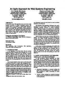
Figure 1. Assignment: q := s + 1 One of the main idea for simplifying the construction of UML structured activities is to use the pull data flow for expression trees. The pull model means that actions requiring data initiate other actions that provide it. Figure 1-(d) shows the push model for evaluating the expression s+1 and adding the result to an activity variable q. As shown in [4], when modeling expressions using the push data flow the control arrives at leaves of the expression tree, then the data cascades through the root, producing the final result. But modeling expression trees using the push model is a tedious task. The proposed framework uses the pull model for expression trees. Figures 1-(a) and 1-(b) shows the graphical and textual notations for the assignment q := s + 1. Both notations can be compiled to the same UML repository model presented Figure in 1-(c). We also propose new graphical notations for conditionals and loops. The graphical notations do not follow Nassi-Schneiderman notations [22] for structured programming. For simplicity we propose the classical flowchart graphical notations. The framework also includes an Agile MDA approach for constructing, running and testing models. Debugging and testing techniques are also included according to the new released standards [15, 13]. In order to be able to exchange executable models with other tools, a UML profile is also defined. The profile defines the mapping between PAL and UML constructs and is similar to the profile defined for AOP executable models [9]. The paper is organized as follows: after this introductory section, the next one presents our agile MDA approach. The third section presents the
AN AGILE MDA APPROACH FOR EXECUTABLE UML STRUCTURED ACTIVITIES105
Procedural Action Language. The last section contains some conclusions and future work. 2. Our Agile MDA Approach Our approach is illustrated using an example program that computes the integer square root (isqrt) of a positive integer. isqrt(s) is the positive integer r which is the greatest integer less than or equal to the square root of s. In order to develop a program we construct a UML model that contains functional model elements and test case model elements. Functional model elements correspond to the program and its operations and are represented as UML activities. Test case model elements are also UML activities and they represent automated tests written for some selected functional model elements. For instance, our model for the above example contains the following elements: an isqrtProgram activity for program, an isqrt activity for computing the integer square root, and a testIsqrt activity which is a test case for isqrt activity. The creation order of these model elements is as follows. 1: First we create the test case model (i.e. testIsqrt activity for isqrt operation) starting from the above informal specification. At this stage we try to understand the requirements by writing test scenarios using UML structured activity constructs. 2: Formal pre and post conditions of isqrt are written after the test case is created. We can return at step 1 to complete the test scenarios based on the defined formal specification. 3: Finally, we define isqrt and isqrtProgram activities using UML structured activity nodes. To allow glass box testing we can mark the functional model elements according to UML Model-level Testing and Debugging Specification. The examples presented in this section contain PAL graphical and textual notations that will be described in the next section. 2.1. Test-first Design Steps. Our proposed agile MDA process includes the test-first design steps [3] as follows. For each new feature of the system we apply the bellow steps. Add a test. The first step is to quickly add a test. Figure 2 shows a test case for isqrt, expressed using (a) a graphical notation and (b) a textual notation. Figure 2-(a) contains an activity diagram that shows testIsqrt activity stereotyped with testCase defined by UML Testing Profile [13]. The assert stereotype defined by our profile is used to make assertions and can be applied for UML 2 CallBehaviorActions. Figure 2-(b) presents the concrete syntax of PAL corresponding to testIsqrt activity.
106
˘ ˆ ˘ I. LAZAR, B. PARV, S. MOTOGNA, I.-G. CZIBULA, AND C.-L. LAZAR
Figure 2. Isqrt Test Case Developers can write the tests using the graphical or the textual notations. Both notations are compiled into the same UML repository model as shown in Figure 2-(c), where a snapshot is presented without pin and parameter objects. For easy of use the framework allows developers to write inline expressions when they construct activities. Inline expressions are represented and evaluated according to the pull model for actions. Run the tests. The second step is to run all the tests to ensure that the new test fails. In order to run the tests the model is verified and the missing elements are reported - in this example isqrt operation. The framework helps developers to generate the missing elements as Figure 3 shows.
Figure 3. Automatically Generated isqrt Operation At this stage developers can write pre and post conditions expressed as OCL expressions [14]. The syntax of PAL includes pre and post constructs as Figure 3-(b) shows. The expressions specified in pre and post sections will be used when the system is run - see section 2.2.
AN AGILE MDA APPROACH FOR EXECUTABLE UML STRUCTURED ACTIVITIES107
Figure 4. Isqrt Operation Definition Add production code. The third step is to update the functional code to make it pass the new test. Figure 4 shows the definition of isqrt operation, without showing the stereotypes in order to save space. As for writing test cases, developers can use either the graphical notation or the concrete syntax of PAL. Figure 4-(b) contains statements that corresponds to an assertion based language [25]. The framework allows and encourages developers to apply design by contract principles [20]. The assert statement corresponds to data assertions - conditions that must hold at a particular location in the code, as defined in [25]. The loopInvariant statement can be used inside loops and it is a particular data assertion that states what must hold in each repetition of a loop. The loopVariant statement introduces a strictly monotonic decreasing function used for loop termination. All these constructs can be used when the program is run - see section 2.2. Run the tests. The fourth step is to run the tests again. Once the tests pass the next step is to start over implementing a new system feature. 2.2. Debugging Techniques. How to enter input data for executable models and how to start the execution represent two requirements for executable models [12]. Programs represent in our framework the entry points for model execution. Like operations, programs are also modeled as UML activities. PAL contains input and output statements that allow developers to enter data
108
˘ ˆ ˘ I. LAZAR, B. PARV, S. MOTOGNA, I.-G. CZIBULA, AND C.-L. LAZAR
before model execution and to view the program results. In this context running a model means starting the execution from an activity stereotyped with program. Figure 5 shows a program that reads an integer, computes the integer square root of that value, and writes the result. When the program is run the user is prompted to enter an integer value and the results are sent to a console.
Figure 5. Isqrt Program The debugging techniques are defined according to Model-level Testing and Debugging Specification [15]. Figure 6 presents an extract of the infrastructure of our framework. All classes except ModelEditor and Debugger classes, belong to the Test Instrumentation Interface (TII) metamodel from [15]. In our context, the system under test (SUT ) contains only a DeployedComponent which is a program. Breakpoint represents a location or incident within the program that is of interest. IncidentBreakpoints can be set on any named element within a model and ActionSemanticBreakpoints can be set only on actions. Incident and action breakpoints can be set manually on
Figure 6. Debugging Infrastructure model elements when the model is constructed (using the ModelEditor). After Debugger is started, it notifies the editor when incident and action breakpoints are encountered.
AN AGILE MDA APPROACH FOR EXECUTABLE UML STRUCTURED ACTIVITIES109
Another option is to inspect the program execution regarding the builtin assertion based constructs (pre, post, assert, loopVariant, loopInvariant). The Debugger component can automatically generate incident breakpoints (a) when encountering assertions, loop invariants, and loop variants, (b) before entering a method - breakpoint set on precondition, and (c) before returning from an operation - breakpoint set on postcondition. When the debugger is paused developers can inspect the program state, evaluate expressions that use program elements, including the expressions of assertion based constructs. 3. Procedural Action Language The Procedural Action Language (PAL) is introduced to simplify the construction of UML structured activities. PAL defines a concrete syntax for representing UML structured activity nodes for loops, sequences of actions and conditionals. The PAL syntax is also used for writing assignment statements and expressions in structured activity nodes. PAL also includes assertion based constructs as described in the previous section. For these expressions, PAL uses OCL expressions.
Figure 7. Snapshot PAL Abstract Syntax Figure 7 presents a snapshot of the core part of the abstract syntax of the language. The missing parts of the abstract syntax refer to expressions and assertion based statements. A PAL profile (see Figure 8) is defined in order to be able to exchange models with other UML 2 compliant tools. 3.1. Operations and Program. As the examples from Figure 5 and 4 show, the programs and procedures corresponds to UML activities. A UML Activity
110
˘ ˆ ˘ I. LAZAR, B. PARV, S. MOTOGNA, I.-G. CZIBULA, AND C.-L. LAZAR
Figure 8. PAL UML Profile has parameters, local variables, preconditions and postconditions, so we have a direct mapping from PAL Program and Procedure meta classes to the UML Activity meta class.
Figure 9. Statement Blocks and UML Sequence Nodes 3.2. Statement Blocks and UML Sequence Nodes. An UML sequence node is a basic structured node that executes a series of actions in order. The PAL statement blocks correspond to UML sequence nodes. The UML 2 standard does not indicate a standard graphical notation for sequence nodes. Our proposed graphical notations for sequence nodes are presented in Figure 9-(a) and (b). 3.3. Variable Definition and Assignment Statements. The PAL variable definition statements can be placed inside statement blocks and can also have expressions for initializing their values. The PAL variables are mapped
AN AGILE MDA APPROACH FOR EXECUTABLE UML STRUCTURED ACTIVITIES111
to UML Activity or StructuredActivityNode variables. For instance the variable p defined in line 10 of Figure 4-(b) belongs to the UML loop node that contains the variable definition, while the local variables q defined in line 5 of Figure 4-(b) belongs to isqrt activity. The UML AddVariableValueActions correspond to PAL assignment statements because the left hand side of a PAL assignment is restricted to be a variable. As noted in section 1 we add the constraint for using the pull action model for evaluating the right hand side expression - which is represented and evaluated as a CallBehaviorAction. 3.4. If Statement and UML Conditional Node. The PAL IfStatements correspond to UML ConditionalNodes. In case the else part is missing, the corresponding UML ConditionalNode has only one Clause, otherwise two Clauses. For simplicity we restrict the body of UML clauses to be sequence nodes. The proposed graphical notations for if statements are presented in Figure 10-(a) and (b) (UML 2 standard does not indicate a standard graphical notation for sequence nodes).
Figure 10. If Statement and UML Sequence Nodes 3.5. While Statement and UML Loop Node. Pre tested UML LoopNodes correspond to PAL while statements. Similar to conditional nodes we restrict the body part loop nodes to be sequence nodes. 3.6. Other Statements. The PAL input statements correspond to UML AddVariableValueActions. The grahical notation must only indicate the variable - the right hand side must be undefined. The output, return, and loop variant statements are CallBehaviorActions, that is all indicate an expression to be printed, returned, respectively checked.
112
˘ ˆ ˘ I. LAZAR, B. PARV, S. MOTOGNA, I.-G. CZIBULA, AND C.-L. LAZAR
Figure 11. While Statement and UML Loop Node The assertion based statements, assert and loop invariant, are mapped to UML Constraints or CallBehaviorActions. The loop invariant statement is restricted to be applied only inside loop nodes.
4. Conclusions and Future Work In order to obtain an agile MDA framework for UML structured activities, this paper has introduced a Procedural Action Language and a corresponding UML profile. A concrete syntax and new graphical notations for structured activities have also been defined for this language. The introduced textual and graphical notations can be used to easily construct, run and test executable models according to Agile Alliance principles. Models based on the introduced profile can be constructed with any UML tool, or can run in any UML tool with execution capabilities. As future work we intend to extend the language with object oriented constructs. Such a language should also support mappings to general UML 2 activities. Additionally, model transformation capabilities must also be extended. We also intend to add refactoring techniques to the presented Agile MDA approach in order to become a test-driven development method for executable models.
ACKNOWLEDGEMENTS This work was supported by the grant ID 546, sponsored by NURC Romanian National University Research Council (CNCSIS).
AN AGILE MDA APPROACH FOR EXECUTABLE UML STRUCTURED ACTIVITIES113
References [1] Telelogic AB. UML 2.0 Action Semantics and Telelogic TAU/Architect and TAU/Developer Action Language, Version 1.0. 2004. [2] Scott W. Ambler. Agile Model Driven Development (AMDD). http://www.agilemodeling.com/essays/amdd.htm, 2007. [3] Kent Beck. Test-Driven Development By Example. Addison Wesley, 2002. [4] Conrad Bock. Uml 2 activity and action models, part 6: Structured activities. Journal of Object Technology, 4(4):43–66, 2005. [5] Kennedy Carter. The Action Specification Language Reference Manual. http://www.kc.com/, 2002. [6] Eclipse.org. Eclipse Modelling Framework. http://www.eclipse.org/emf. [7] Pierre-Alain Muller et al. On executable meta-languages applied to model transformations. In Model Transformations In Practice Workshop, Montego Bay, Jamaica, 2005. [8] Susumu Hayashi et al. Test driven development of uml models with smart modeling system. In Lecture Notes in Computer Science, volume 3273, pages 395–409, 2004. [9] Lidia Fuentes and Pablo S´ anchez. Designing and weaving aspect-oriented executable uml models. Journal of Object Technology, 6(7):109–136, 2007. [10] Object Management Group. MDA Guide Version 1.0.1. http://www.omg.org/docs/omg/03-06-01.pdf, 2003. [11] Object Management Group. Meta Object Facility (MOF) 2.0, Core Specification. http://www.omg.org/cgi-bin/doc?ptc/04-10-15/, 2004. [12] Object Management Group. Semantics of a Foundational Subset for Executable UML Models RFP. http://www.omg.org/cgi-bin/apps/doc?ad/05-04-02.pdf, 2005. [13] Object Management Group. UML 2.0 Testing Profile Specification. http://www.omg.org/cgi-bin/apps/doc?formal/05-07-07.pdf, 2005. [14] Object Management Group. Object Constraint Language Specification, version 2.0. http://www.omg.org/cgi-bin/apps/doc?formal/06-05-01.pdf, 2006. [15] Object Management Group. Model-level Testing and Debugging. http://www.omg.org/cgi-bin/doc?ptc/2007-05-14/, 2007. [16] Object Management Group. UML 2.1.1 Superstructure Specification. http://www.omg.org/cgi-bin/doc?ptc/07-02-03/, 2007. [17] Dimitrios S. Kolovos, Richard F. Paige, and Fiona A.C. Polack. The epsilon object language (eol). In Proc. of European Conference in Model Driven Architecture (ECMDA), pages 128–142, Bilbao, Spain, 2006. [18] Stephen J. Mellor. Agile mda. Technical report, Project Technology, Inc., 2005. [19] Stephen J. Mellor and Marc J. Balcer. Executable UML: A Foundation for Model-Driven Architecture. Addison Wesley, 2002. [20] Bertrand Meyer. Applying design by contract. Computer, 25(10):40–51, 1992. [21] P.-A. Muller, P. Studer, F. Fondement, and J. Bzivin. Platform independent web application modeling and development with netsilon. Software and System Modeling, 4(4):424–442, 2005. [22] I. Nassi and B. Schneiderman. Flowchart techniques for structured programming. ACM Sigplan Notices, 8(8):12–26, 1973. [23] Bazil Parv, Simona Motogna, Ioan Lazar, Istvan-Gergely Czibula, and Codrut-Lucian Lazar. Comdevalco - a framework for software component definition, validation, and composition. Studia Univ. Babes-Bolyai, LII(2), 2007. [24] Inc ProjTech AL: Project Technology. Object Action Language. 2002.
114
˘ ˆ ˘ I. LAZAR, B. PARV, S. MOTOGNA, I.-G. CZIBULA, AND C.-L. LAZAR
[25] Herbert Toth. On theory and practice of assertion based software development. Journal of Object Technology, 4(2):109–129, 2005.
Department of Computer Science, Faculty of Mathematics and Computer ˘ lniceanu, Cluj-Napoca 400084, RoScience, Babes¸-Bolyai University, 1 M. Koga mania E-mail address: {ilazar,bparv,motogna,czibula}@cs.ubbcluj.ro