consumer electronics may be needed to control ... a new optics keyboard whose keys were all infrared receivers .... [6] A. Yariv, âOptical electronics,â Ch.2, pp.22-.
An Application of Infrared Technique to Control a Computer Keyboard for Handicap 1,2Yu-LuenChen, 3Walter H. Chang, 4May- Kuen Wong, 4Tan-Fuk Tang, ITe-Son Kuo 'Department of Electrical Engineering, National Taiwan University 2Department of Electronic Engineering, Hwa-Hsia College of Technology and Commerce 3Department of Biomedical Engineering, Chung Yuan Christian University 4Department of Rehabilitation Medicine, Chang Gung Memorial Hospital
Abstract A new infrared-controlled keyboard instead of the conventional computer keyboard was developed for those with hand dysfunction. The infrared transmitter with laser director was placed on the eyeglasses, and the keys of the conventional computer keyboard were all took place by infrared receivers. In the infrared receivers we designed a modulized circuit to receive, demodulate and process the infrared signals. The modulized circuit used signal processing technique to convert the astable signal of the infrared receiver to a standard pulse train which could be used as control signal easily.
module was combined with the infrared receiver and infrared signal processing circuit. Every key needs an individual infrared receiver module for receiving and processing infrared. After counting the focused time of the receiver to make sure the input of the infrared, the module send a positive pulse to the encoders. There were three groups of encoder chips included, and either encoder was made of 16 by 4. The Intel8751 was selected to be the central processing unit (CPU) and interface of the infrared control keyboard. The interactive input-output system is composed of the conventional keys which were ail infrared receivers. To make sure the inputs from keys, the CPU should be played as a counter to count the delayed time of input pulses. The Intel8751 was used to receive the pulses from its portA and portB by polling method. If either of the two ports received a positive pulse, the Intel8751 will send out a pulse from its portC and portD to the decoder through the mapping table in its RAM. There were three groups of decoder chips included, and either decoder was made of 4 by 16. The decoder received a pulse from Inte18751 and to control the SSR switches (solid state relay) between the scan lines and return lines of the keyboard interface (8279). At the same time the Intel8751 send out a pulse as a clear signal to every infrared receiver module circuits of keys for preparing next input. Because the infrared is not visible, the user could not sure whether the infrared points to the receivers of number or alphabet which he wanted. Therefore, the low power laser (< O.lmW) was played as a director to point to the numbers and alphabets which the user wanted to input.
1.Introduction A computer keyboard typically used in consumer product is composed of the well known circuits. However, the conventional keyboard is useless for persons with hand dysfunction. In recent years, the handicap were greatly increased in the world. They have many different ways to cope with the challenges it poses. A special type of consumer electronics may be needed to control environment for their daily life. A special computer keyboard using the image processing technique which classified the inputs by the image on the eyeballs has been developed. However, the system requires high cost and hardware complexity. In this paper, we proposed a new computer input system using infkared technique to overcome the problems met by the handicap. The new developed infrared keyboard system configuration was shown in figure1. We designed a new optics keyboard whose keys were all infrared receivers. The infrared keyboard was placed between the user and computer monitor. The distance maximal between the infrared transmitter and the infrared receiver is 50 cm.
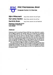
2.The infrared transmitter module The infrared transmitter was driven by NE555 astable
multivibrator circuit which produced 32.8 kHz oscillated frequency. The Honywell SEP8705 AlGaAs infrared emitting diode (spectral bandwidth = 80 nm, beam angle = 15' ) was selected to be as infrared transmitter which combined with a low power laser and a focused lens. The focused lens which was placed between the infrared
The transmitter module (2.5cm*1A m * 1Scm) included: infrared transmitter(A), low power laser transmitter(B) and the focus lens(C) [3-91. The infrared receiver
0-7803-4371-9/97/$10.00 0 1997 IEEE
83
A: Infrared transmitter B: Laser transmitter C: Optics lens
I
o
b
+
I = I 0.2 cm
I . 1 ;
r-
! 1 ;
.....
-
II
Decoder Chips #I ,#2,#3
I
Keyboard Interface (8279)
Return lines
_I I
Keyboard switch array
Figure 1 . The system configuration of the new developed infrared keyboard
transmitter and receiver was used to convert the scatter infrared into parallel light, that help the infrared to aim the desired keys accurately.
3. The infrared receiver module The infrared receiver module was shown in figure2, including the infrared receiver (HC-370), nonretriggerable circuit and the shift registers. In the infrared receiver module, the HC-370 optic receiver MOD ULES was selected and its distance was 10 meter, 3Lp = 9400 mm, 8 = 45", and the demodulation frequency = 37.9 kHz [1][2]. The non-retriggerable circuit was combined with logic
84
gates and flip-flops, which could convert astable output wave of the HC-370 to a cycled or standard pulse train. The relationshiip between the input and output of the HC370 and the non-retriggerable circuit were shown in figure3. It was shown in figure3(a) the output of HC370 was in high level (+5V), while there was no infrared input. After the infrared was received by HC-370, the output of HC-370 became astable, shown in figure3(b). The non-triggerable circuit (convertthis astable signal to a standard pulse train which was shown in figure3(d). The duration and duty cycle of the standard pulse was depended on R1 and C1, was shown in figure2. The standard pulse was as a clock and sent to the shift registers, which played as a time counter while the user focused on the infrared receiver. The LED1 lighted while the input processing was completed.
Infrared Input
IN1
1
HC-370 Infrared Receiver
Figure2. The infrared receiver and infrared signal processing module
_-
+5v Theoutput of HC370
OUT1 (a)
n,
( while there is no infrared input )
...-.----
Theoutput of HC370 (while there is infrared input )
OUT1 (b) -.
-_
- . - __
1
-
IN2 (c)
I
OUT2 (d) 1
-
-
,"
I
-_
',"v"
I
Theoutput of Q1 ( while there is infrared input )
+EN The output of non-retriggerablecircuit ( while there is infrared input ) OV
1
1 sec
Figure3.The output signals of the receiver module, OUTl(a), OUTl(b), IN2(c), and OUT2(d) 2. The modulized designed could avoid the interference of infrared receivers (from one key to the others). 3. The cost of the infrared-controlled input system will be lower than other systems. 4.The keyboard for the handicap will be more convenient than other inputkontrol methods.
4.Summary The photographs of the infrared transmitter module and the infrared receiver module were shown in figure4 and figure5, respectively.
The infrared controlled interface could be also implanted into the manual switch system in environmental control for the handicap, like the wheelchair controlled panel, light switch, TV control...etc..
The features of the new developed infrared-controlled keyboard are summarized below: 1.The new developed infixed receiver module could identify the infrared signal easily.
85
%Acknowledgment [3] [4]
We thank physical therapists Yen-Chen Li and Ying-Ying Shih, Department of Rehabilitation Medicine, Chang Gung Memorial Hospital, the students, Department of Electronic Engineering, Hwa-Hsia College of Technology and Commerce.
[5]
[6] [7]
6.Reference
[SI [ l ] TAIWAN LITON ELECTRONIC CO.,LTD., “LITEON Optoelectronics, short form,” pp. 37-40, 1996-1997. [2] TAIWAN LITON ELECTRONIC CO.,LTD.,
[9]
“LITEON Optoelectronics, DATABOOK,” Ch.4, 1996-1997. E. Hecht, “Optics,” Ch15,pp. 129-210, 1990. W. J. Mooney, “Optoelectronic devices and principles,” Ch.6, pp.137-152, 1991. W. J. Mooney, “Optoelectronic devices and principles,” Ch.11, pp.280-301, 1991. A. Yariv, “Optical electronics,” Ch.2, pp.2252,1985. T. S. k’u, I. C. Khoo, “Principles of optical engineering,” Ch.3, pp. 59-19, 1990. W. J. Smith, “Modeim optical engineering,” Ch.12, pp. 372-2179, 1991. M. Young, “Optical and lasers,” Ch.8, pp.192-221, 1993.
Figure4. The photograph of the infrared transmitter module
FigureS. The photograph of the infrared receiver module
86