21ST INTERNATIONAL CONFERENCE ON ENGINEERING DESIGN, ICED17 21-25 AUGUST 2017, THE UNIVERSITY OF BRITISH COLUMBIA, VANCOUVER, CANADA
AN APPROACH FOR HOLISTIC MODEL-BASED ENGINEERING OF INDUSTRIAL PLANTS Hooshmand, Yousef; Adamenko, Dmytro; Kunnen, Steffen; Köhler, Peter University of Duisburg-Essen, Germany Abstract Systems Engineering has been proven to be an effective approach to cope with the increasing complexity of systems, consisting of mechanical, electrical, electronic and software components. However, as the systems getting more interdisciplinary and in particular more software-intensive, classical document based methods cannot efficiently master the growing complexity. In contrast, model-based approaches look promising in gaining the control over the complexity of systems and the development processes. For this, a formalized system model, integrated in the IT landscape, is indispensable. Thus a pragmatic approach has been developed, which enables a (semi-)automatic creation of formalized system models in SysML. Furthermore, an ontology has been developed to define the relationships and to enrich the system model with more semantic. The system model and the ontology will be then used to connect the domain models and artefacts along the development process. This ensures the required traceability and enables, inter alia, an automatic impact analysis, if any change arises. The federalized solution for the heterogeneous model landscape of industrial plants is applicable to other domains. Keywords: Systems Engineering (SE), Integrated product development, Product modelling / models, Ontologies, Model-based engineering Contact: Dr. Yousef Hooshmand University of Duisburg-Essen Institute for Product Engineering Germany
[email protected]
Please cite this paper as: Surnames, Initials: Title of paper. In: Proceedings of the 21st International Conference on Engineering Design (ICED17), Vol. 3: Product, Services and Systems Design, Vancouver, Canada, 21.-25.08.2017.
101
1
INTRODUCTION
Growing diversity of customer requirements increases constantly the multidisciplinary nature of the products and the product creation processes and thus increases the endogenous and the exogenous complexity. This requires a closer cooperation among different disciplines and even organizations, which consequently increases and complicates the communication and the coordination effort. In addition, the products are increasingly evolving into software-intensive solutions with mechanical, electrical and electronic components, which need to be considered as an integrated product or more precisely as an integrated system. This is indeed the case for the manufacturers of both consumer goods and (mainly) individualized industrial capital goods and industrial plants. Systems Engineering (SE) approach has been emerged as an effective way to cope with the escalating development complexity of systems as well as the arising changes. The origin of SE can be traced to the 1930s and even on its earliest application, SE has been useful by reducing the risk associated with new systems or modifications to complex systems. SE has been defined, inter alia, as "an interdisciplinary approach and means to enable the realization of successful systems. It focuses on defining customer needs and required functionality early in the development cycle, documenting requirements, and then proceeding with design synthesis and system validation while considering the complete problem" during the entire system life cycle - from the early concept phase to the final system disposal. (INCOSE 2015) The increasing complexity of interdisciplinary products and systems can, however, no longer be mastered with classical document based SE methods. Model-centric approaches are, in contrast to document-centric methods, capable of formal definition and description of systems, which are necessary for enabling, inter alia, the systems thinking perspective and the automatic processing of interrelationships among system elements as well as the impact assessment of changes. Hence, ModelBased Systems Engineering (MBSE) approach gained growing attention during the last decade and is going to be one of the main pillars of the next industrial revolution named "Industry 4.0". In an elaborate model-based approach, a coherent use of information management is required to merge, co-manage and semantically connect the evolving system architecture and the generated artefacts during the entire system life cycle stages (Hooshmand et al. 2016). Planning and engineering of complex systems like industrial plants is characterized with a heterogeneous landscape of software tools and data formats, needed in different engineering disciplines, such as mechanical, electrical, software and civil engineering (Abele and Grimm 2013). However, most software tools cannot communicate directly with each other for the lack of interoperability. As a result, product data is often kept redundant in order to be used in various applications (Kaufmann et al. 2015). The problem is also intensified by the fact that the full extent of the created data and information in different software tools are usually available only in proprietary formats, which are not fully readable or interpretable in other tools (Hooshmand et al. 2016). This Paper proposes a holistic model-based approach in industrial plant engineering and construction. It considers the SE processes along all system life cycle stages and integrates the generated models and artefacts during these life cycle phases. A formalized system model of the industrial plant will be created (semi-)automatically by extracting the information from models, which have been generated by domain engineers. To increase the traceability of changes during the plant engineering, an ontology is developed, which describes the relationships among different model classes, among system elements and finally between model classes and system elements. This provides, furthermore, the basis for impact analysis of changes. The proposed approach increases the traceability in the organization and enables a pragmatic implementation of MBSE methods in plant engineering. It is, however, applicable to other sectors too. 2
MODEL-DRIVEN DEVELOPMENT OF SYSTEMS
2.1 Complex systems and complex development processes Companies with individualized products, such as companies in the machinery and industrial plant construction sector, are in the tension area between the complete individualization of the product portfolio and the long-desired scale effects. Generally, it is attempted to meet different customer requirements by creating and offering customer-specific variants, which serve as an important distinguishing feature for improving the competitive position. This, however, drastically increases the
102
ICED17
variant diversity and the complexity of the product spectrum, which is associated with more efforts and increases the costs in almost all areas of the company. (Hooshmand 2015) The increased degree of individualization requires an earlier involvement of customers in the development process (Hildebrand 1997). The earlier customer engagement increases consequently the interaction with the customer and strengthens the customer integration, which enables the customer to influence increasingly not only the to be developed products, but also the development processes of the manufacturer (Gausmann 2009, Hildebrand 1997). The customer-oriented development of the individualized products and systems presents new challenges due to the constant change of internal and external conditions as well as customer requirements changes during the order processing. This leads to a further increase in the complexity of the order processing and the development process, which, inter alia, necessitate an increase of the flexibility within the company. (Hooshmand 2015) The situation in industrial plant design and construction is even more intense, as not only different engineering disciplines, but also different organizations with sometimes contradicting requirements are working on the same project. The engineering and construction processes usually last a few years, which makes a consistent change management more difficult. This includes the changes that often occur both in engineering and construction phases, but are either (never) properly reported and documented or, if reported, their impacts on the system as a whole have been never analysed. 2.2 Systems Engineering (SE) The SE perspective is based on systems thinking, which puts the focus on the whole (system) and how the parts within the whole (system elements) interrelate to each other and to the whole (system). For this purpose, SE "integrates all disciplines and specially groups into a team effort forming a structured development process that proceeds from concept to production to operation". The inclusion and the contribution of exports across different disciplines helps to unveil the (hidden) interrelationships of the system elements and thus to prevent or to minimize the undesirable consequences. (INCOSE 2015) ISO/IEC/IEEE 15288 (2015) assorts thirty SE processes in four process groups. These are technical processes, technical management processes, agreement processes and organizational project-enabling processes. It also defines six generic life cycle stages, through which a system progresses "as the result of actions, performed and managed by people in organizations, using processes for execution of these actions". The generic life cycle stages are concept stage, development stage, production stage, utilization stage, support stage and retirement stage. (ISO/IEC/IEEE 15288 2015) Due to the growing complexity of systems and system development processes, classical document centric methods cannot meet anymore the SE requirements of the industry and a paradigm change is necessary. Kaufmann and Schuler (2016) define six impediments for an efficient application of SE in the industry. These are informal science, non-transparent benefit, decoupled activities, domain-specific cultures, restricted acceptance and unconnected artefacts (Kaufmann and Schuler 2016). A paradigm shift from document-centric methods to data-driven model-centric approaches looks promising for efficient application of SE and is indeed indispensable for effective coping with the constantly growing complexity of systems and system development projects. 2.3 Model-Based Systems Engineering (MBSE) INCOSE (2007) defines MBSE as "the formalized application of modeling to support system requirements, design, analysis, verification and validation activities beginning in the conceptual design phase and continuing throughout development and later life cycle phases. MBSE is part of a long-term trend toward model-centric approaches adopted by other engineering disciplines, including mechanical, electrical and software". The basic idea of MBSE is thus to formalize the system description as well as to connect the relevant information - needed for the creation of various artefacts during the system development - in a system model (Kaufmann and Schuler 2016). Leveraging the system model as a primary artefact of the systems engineering process is a distinguishing characteristic of the MBSE approach, which enables MBSE to offer the potential to: • enhance product quality, • enhance reuse of the system modelling artefacts, • improve communications among the systems development team, • reduce the time and cost to integrate and test the system, • reduce cost, schedule and risks in fielding a system (SEBoK 2016).
ICED17
103
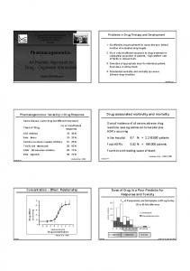
Consequently, the transparency of development steps as well as the traceability of changes increases and the handling of complexity improves (Kleiner and Husung 2016). Methods, modelling languages and tools are three crucial enablers for MBSE. Estefan (2008) performed in 2008 an extensive survey on six MBSE methods1, which have been practiced in different industry projects (Estefan 2008). Since then, new methods have also been developed by various organizations for their internal exertion of MBSE approach (Friedenthal, Moore and Steiner 2015). To advance the MBSE practice in the industry, MBSE methods require still further improvements to "provide a rigorous approach to modeling a system across the full system lifecycle, while being more adaptable to a diverse range of application domains" (SEBoK 2016). Furthermore, a standardized and formalized language like OMG Systems Modeling Language (OMG SysML) is necessary for the formal definition of the system (Friedenthal, Moore and Steiner 2015). OMG SysML is a graphical modelling language based on OMG UML (Alt 2012) and despite some just critiques regarding its practicability and usability, it's going to be the main modelling language of the MBSE approach. Beside the modelling language(s), which need to improve "in terms of their expressiveness, precision and usability", advancing the MBSE practice requires also further enhancement of tools "to support the modeling languages and methods, and to integrate with other multi-disciplinary engineering models and tools in support of the broader model-based engineering effort" (SEBoK 2016). Although different MBSE methods2 follow different (partly organization-specific) SE approaches, most of them support just a few technical processes like system requirements definition process, architecture definition process, design definition process, and partly verification and validation processes. This comprises only the processes in the early stages of the SE, more specifically in the concept stage and to some extent in the development stage. It associates with the upper parts of the V model branches as described in VDI 2206 (2004). To exploit the full potential of MBSE is, however, a model-based approach necessary, which covers the SE processes in all life cycle stages and integrates or rather connects all generated artefacts. 2.4 Model-Based Engineering (MBE) NDIA (2011) describes Model-Based Engineering (MBE) as an integrated approach to engineering, in which all created artefacts and models across all engineering disciplines during the entire system life cycle are an integral part of the technical baseline. In contrast to MBSE, MBE requires and covers the use of different types of models to address different aspects of a product or capability. The models can have different characteristics and types as they are created in different modelling domains like systems engineering (SysML models), hardware engineering (MCAD models), software engineering (UML models), electrical engineering (ECAD models) etc. MBE requires the consistent integration of software tools from different engineering disciplines. (NDIA 2011) MBE tries thus to enable knowledge workers in different engineering disciplines to work with their familiar domain tools, and at the same time tries to integrate and to connect their tools and the generated models and artefacts. An integrated system model, ideally in a product lifecycle management (PLM) system, needs to be used as a backbone. (Kaufmann et al. 2015) Following the MBE approach, Pfenning and Roth (2016) propose a concept named Fully-integrated Model-Based Engineering Environment (FIMBEE), which considers in addition the integration of IoT Platforms and the transformation of system models (e.g. SysML models of the system) in an IoT information model. The FIMBEE concept is described more at higher level and does not define exactly how domain models will interact with each other and with the system model. Pfenning (2017) proposes in his dissertation a detailed approach for integration of PLM and MBSE to support engineering activities. In his approach, the desired system will be developed in three spaces: requirements space, solution space and verification space. The solution space is furthermore divided in three abstraction levels: functional level, logical level and physical level (see Figure 1).
1
Estefan (2008) uses in his survey the term methodology instead of method. A methodology is defined as a collection of related processes, methods, and tools. 2 An introduction to various MBSE methods can be found in Estefan (2008) or also briefly in Allen et al. (2016).
104
ICED17
Figure 1. System model at different abstraction levels, adapted from (Pfenning 2017)
Solution elements (not interim artefacts) of the system model - modelled with SysML - will be managed as configuration item (CI) in a PLM system to be placed under its version control. These CIs are the main elements for a semi-automatic transformation of the system model from the solution space to the verification (simulation) space. The presented approach supports a synchronized system development and simulation based on the system model as a single source of truth. Considering the investigated literature, next chapter proposes a concept for pragmatic realisation of the MBE approach, which, inter alia, considers the interactions of different engineering disciplines with the system model. 3
HOLISTIC MODEL-BASED ENGINEERING IN AN INTEGRATED LANDSCAPE
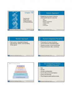
As described in previous section, MBE tries to integrate all models and artefacts, including both discipline-specific models (MCAD, ECAD etc.) and interdisciplinary models, which are necessary for the MBSE approach. Thus, in this section an approach for a Holistic Model-Based Engineering (HMBE) is proposed. It considers all system life cycle stages and enables a pragmatic introduction and integration of the MBSE approach in the organization. Furthermore, the federalized landscape empowers the domain engineers to continue to work with their familiar tools, but at the same time to be supported by the created system model. The necessary steps for HMBE are: • All models and artefacts, which may be created during a system development, will be first classified. Additionally, an ontology will be developed to define the relationships among model classes, among system elements and finally between model classes and system elements. • A MBSE approach will be outlined, which helps to (semi-)automatically create and enrich the desired system model based on already generated discipline models. This includes the creation of a SysML-based model library and the definition of configuration items for a reference structure. • Finally, the integrated landscape will be presented. It describes the federalized landscape and the desired interoperability. Furthermore, the creation of the aforementioned reference structure in a PLM system will be explained in this section. This approach is developed based on diverse characteristics of industrial plant engineering and construction, but is easily transferable and applicable in other industry sectors like aerospace or automotive engineering. 3.1 Classification of artefacts and ontology-based definition of relationships The classification of created artefacts along the SE as well as the definition of their relationships is a primary task in an MBE approach. It helps, inter alia, to better understand the IT and model landscape and to find easier the optimization potentials. As mentioned previously, a system will be fully described and defined with both interdisciplinary models as well as discipline-specific models. Interdisciplinary models have been classified almost as the four main diagram classes of SysML (Friedenthal, Moore and Steiner 2015), however, they do not need to be written or created in SysML. Following Hooshmand et al. (2016), the classification of discipline models reflects the main engineering disciplines. The SysML diagram in Figure 2 shows the classification of all system artefacts. It shows, however, just a high-level classification example. A finer classification (especially for discipline models) should be created rather organization-specific.
ICED17
105
Figure 2. Classification of discipline models and interdisciplinary models
As illustrated in Figure 2, the informal model, comprising e.g. assembly documentations, is also considered as a discipline model. The information content of each model can be provided as native or/ and neutral formats. Important system relevant information should also be provided as meta data to increase their availability. Next, the ontology of relationships among model classes, among system elements and between model classes and system elements will be created. These ontologies will be mapped later into stereotypes in a SysML profile to be used for the creation of the system model in SysML. Thereby, the created system model can be transformed back easily into an OWL (Web Ontology Language) model for advanced analysis of (hidden) interconnections and dependencies or also for performing Queries. Three possible relationships among model classes are defined as • , and . Discipline models usually interdisciplinary models. However, among discipline models or among interdisciplinary models, it exists more often a or a relationship. For example, MCAD models architecture models, but they ECAD models to follow their changes etc. The definition of relationships among model classes is more or less organization- and SE-specific. The relationship between model classes and system elements are • and . A model, for example a MCAD model, a system element, like a pump. On the other side, each system element es various models. This is especially necessary for increasing the traceability of model changes. More importantly is the definition of relationships among system elements, which are, inter alia, important for impact analysis of changes. Following Pimmler and Eppinger (1994), they are • , , , , and . Based on these ontologies, it will be possible to create a semantic and interpretable model of the system. For example, the aforementioned system element, pump, a pressure vessel, a control cabinet and an electro motor. These ontologies can also be defined finer based on organization needs. For example, material flow can be rewritten in hydraulic flow, pneumatic flow, etc. 3.2 A MBSE approach for (semi-)automatic creation of the system model Most MBSE methods consider only the first few technical SE processes (including business analysis, requirements definition and architecture definition) and partly the final verification and validation (V&V) processes. The result of MBSE methods is formalized system models, which should be ideally used as a basis for succeeding SE processes. INCOSE OOSEM is one of the most referenced MBSE methods in the industry, which uses SysML as the modelling language and combines traditional topdown waterfall SE approaches with object-oriented techniques (Friedenthal, Moore and Steiner 2015).
106
ICED17
OOSEM divides the system architecture in three abstraction levels, namely functional, logical and physical levels with decreasing abstraction. The same architectural levels have also been used in other approaches like RFLP (Requirements engineering, Functional design, Logical design and Physical design) approach, described by Kleiner and Kramer (2013). The proposed MBSE approach in this paper is developed based on OOSEM. It comprises requirements engineering as well as architecture development at functional level, logical level and physical level. The system model will be created (semi-)automatically based on models and artefacts, created by domain engineers. This approach has been named Systems Re-Engineering by Kaufmann and Schuler (2016). As the SE process proceeds, the system model will be enriched and serves at the same time as the single source of truth for subsequent SE activities. Requirements engineering: The definition of stakeholder and system requirements as well as their integration in the system model is indispensable for ensuring the traceability of requirements fulfilment level and occurring requirements changes in subsequent development stages. In industrial plant engineering, the requirements are often documented as textual and partly graphical specifications in one or more pdf files. Even for small plants, they encompass a few thousand requirements, which need to be identified, analysed and decomposed in single requirements with unique identifiers to make their integration in the system model (stereotypes «requirements») possible. A well-developed approach for automatic transformation from a document-centric requirements engineering to a model-centric one is discussed in Götz and Donges (2016). Architecture development: This step is the core of the MBSE approach and will be done at three abstraction levels. Following Pearce and Friedenthal (2013), • Functional level comprises only functions. The functional structure is a solution-independent representation of the system design. • Logical level comprises logical components, which represent technology- and implementationindependent abstractions of physical components. The logical structure resembles the final system design. • Physical level comprises tangible items. The physical structure defines a specific design implementation. It can thus be used, for instance, for creation of model nodes in a 3D-CAD tool. Considering the fact that different industrial plants use more often same system elements just in different constellations and sequences, creating a model and variant library for system elements (stereotypes «functional», «logical» and «physical») is a preliminary step, which enables a cross project usage of elements. This is specially the case at functional and logical levels and to some extent at physical level. Furthermore, the definition of relationship ontologies from functional elements to logical elements () as well as from logical elements to physical elements ( or ) can be done partly project- and plant-independent. This serves, inter alia, to exploit synergy effects by formalizing the extensive knowledge scattered in different project teams and disciplines and making them available for everyone in the organization. Engineering of industrial plants, including also power plants, occurs in various iterations. Based on stakeholder and system requirements, a procedural layout design - including e.g. functional, thermal and process analysis - follows. First iterations produce both rough functional3 layouts (functional structures) and process layouts comprising only technology- and implementation-independent components (logical structures). The outcome of final iterations is fine specified process layouts (physical structures). The results of the plant engineering process are documented mainly in Piping and instrumentation diagrams (P&ID), created often based on various international standards. These P&IDs, created by domain engineers, will be used to successively develop the system model in SysML at different levels. The creation and enrichment of the system model in SysML is, however, not limited to P&IDs and other models and artefacts will be used in further life cycle stages. The P&IDs contain almost all needed information regarding system elements of the plant and the relationships among those system elements. P&IDs, created by professional process engineering tools, are machine-readable and their information can be read and transformed into SysML models. Thus, the system architecture can be created (semi-)automatically and visualized in block definition diagrams (bdd) and internal block definition diagrams (ibd). A manual task will be the allocation of the
3
Based on plant size, engineering process and utilized software, the functional structure may be an integral part of the logical and physical structures and does not exist separately.
ICED17
107
requirements to the elements of the system architecture to ensure their traceability. Because of the project- and plant-independent definition of relationships among elements at different levels, possible plant designs and solutions can be analysed and compared even during the first design iterations by using the functional and logical structures. The system model in SysML will be created based on the beforehand created libraries (including components, ports and connectors) and the defined stereotypes in the SysML profile, which comprise also the ontologies of the last section (see Figure 3). For this, a database has been created based on SysML-notations to manage both the model and variant libraries as well as the project-specific system models. System models will be created simultaneously in the database and in the bidirectional integrated SysML modelling tool Cameo Systems Modeler.
Figure 3. Building blocks of the MBSE approach (implemented in a SysML-based database)
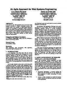
There exist professional tools for plant simulation as well as dynamic modelling and analysis. Furthermore, most engineers are only familiar with their domain tools. Thus, SysML diagrams for parametric or behaviour modelling are not considered in this paper, however, if needed, they can be added (semi-)automatically based on the same procedure, described above. In this work, the stored system model in the database will be used to create (or prepare) the needed simulation models. Thus, the transformation of the system model requires a deeper integration of simulation tools. 3.3 An Integrated MBE Creation of an integrated landscape is the final necessary step to achieve the desired Holistic ModelBased Engineering. This will be realized in a federalized landscape with ideally a PLM system as a hub. For MBE and MBSE integration, it's necessary to find a common structure or rather a reference structure, which connects the created models and artefacts in different life cycle stages of SE to each other and to the system model. Furthermore, to ensure the traceability of changes and connections, both system models and created artefacts need to be under version control or rather configuration management. A pragmatic solution is to use the configuration management capability of PLM systems and extend their functionalities with required ones to make the long-desired integration of MBE and MBSE possible. The above-mentioned reference structure will be created based on the system model described in previous section. Thus, the elements of the system model will be defined as configuration items (CI) in the PLM system. Regarding the defined ontologies, each configuration item es various models and artefacts and at the same time each model or artefact one or more configuration items. This ensures that the changes of all models and artefacts are documented and linked to each other. Figure 4 shows exemplary the possible relationships between the configuration item pump with its assigned artefacts and with the configuration item electric motor. Thus, not only the changes stay traceable, but also the change impacts analysis will be possible. This can be done either by transforming the information into OWL and using an OWL-based tool or by extending the functionality of PLM systems to (OWL-)reasoning features. Figure 4 shows a simplified version of model and artefact integration. Indeed, the proposed approach integrates the models and not the files. For example, only the system model element pump (NOT the file containing the entire SysML model of the system) is connected to the configuration item pump. The IT landscape of any organization is full of authoring tools and data processing systems with various databases, which makes a direct integration almost impossible. Thus, a federalized solution is required to integrate different tools and information resources. Considering the OSLC (Open Services for Lifecycle Collaboration) approach, it suffices to link the configuration items to the models and artefacts
108
ICED17
in their native environment or data source. For example, as most system modelling tools manage the created system model in their own team-database, a further saving of the system model in PLM causes a double data storage. Thus, the entire IT landscape needs to be analysed to decide where and how to manage which data (including native-, neutral- and metadata).
Figure 4. Interactions of configuration items and artefacts (implemented in keytech PLM)
Plant engineers usually use P&IDs to create a work breakdown structure (WBS) as their reference structure both for project management and for document management. As the proposed reference structure, comprising the configuration items, is also created (indirectly) based on P&IDs, it gains easier acceptance in the organization. The same structure can be used for all project management activities, which reduces the mapping effort and increases the traceability. In addition, the federalized landscape reduces the need for bidirectional tool integration, as the configuration items work as nodal points between different tools and provide them with required information (usually metadata). This increases the Interoperability of the entire IT landscape. 4
CONCLUSION
An approach has been proposed and prototypically implemented for Holistic Model-Based Engineering (HMBE) in industrial plant engineering and construction. It provides a way for pragmatic MBSE introduction into the organization by (semi-)automatic creation of system models based on SysMLbased model and variant libraries. The domain engineers can continue to work with their familiar tools and have the continually evolving system model right at their fingertips as the single source of truth. The defined ontology helps to increase the traceability during the system development and enables the impact analysis of changes. Furthermore, the introduction of configuration items as nodal points in PLM and the federalized model integration helps to increase the total interoperability of the IT landscape. The created ontology in this paper needs to be extended to cover the tasks and resources required to execute the tasks. Thus beside impact analysis, the cost estimation of new plant developments or occurring changes will be possible. Especially, as the assigned artefacts to each configuration item are usually project-independent, cost estimation of various scenarios can be done in early development phases. Further modules, for example, for integrating Failure Mode and Effects Analysis (FMEA) are necessary. The possibilities and needs for automatic extension of the system model with other SysML diagrams need to be investigated in more detail. Finally, to increase the interoperability, both the OSLC based tool integration as well as data formats of created models and artefacts need to be investigated to ensure a lossless model transformation. REFERENCES Abele, L., Grimm, S. (2013) “Knowledge-based Integration of Industrial Plant Models”, IEEE Industrial Electronics Society (IECON), Vienna, 10.-13. November 2013, IEEE, Piscataway, pp. 4392-4397. http://dx.doi.org/10.1109/IECON.2013.6699842
ICED17
109
Allen, C., Di Maio, M., Kapos, G.-D. and Klusmann, N. (2016), “MDDP: A pragmatic approach to managing complex and complicated MBSE models”, IEEE International Symposium on Systems Engineering (ISSE), Edinburgh, 3.-5. October 2016, IEEE. http://dx.doi.org/10.1109/SysEng.2016.7753165 Alt, O. (2012), Modellbasierte Systementwicklung mit SysML, Carl Hanser Verlag, München. https://doi.org/10.3139/9783446431270 Estefan, J.A. (2008), Survey of Model-Based Systems Engineering (MBSE) Methodologies, INCOSE. Available at: www.omgsysml.org/MBSE_Methodology_Survey_RevB.pdf (Accessed December 06) Friedenthal, S., Moore, A. and Steiner, R. (2015), A practical guide to SysML, The systems modeling language, 3th Edition, Morgan Kaufmann, Waltham. https://doi.org/10.1016/c2013-0-14457-1 Gausmann, O. (2009), Kundenindividuelle Wertschöpfungsnetze. Gestaltungsempfehlungen unter Berücksichtigung einer auftragsorientierten Produktindividualisierung, Gabler Verlag, Wiesbaden. https://doi.org/10.1007/978-3-8349-9917-7 Götz, A. and Donges, Ch. (2016), “Automatisierter Übergang vom dokumenten- zum modell-zentrierten Requirements Engineering als Ausgangsbasis für MBSE”, Tag des Systems Engineering, Herzogenaurach, 25.-27. October 2016, Hanser Verlag, München, pp. 301-310. https://doi.org/10.3139/9783446451414 Hildebrand, V. G. (1997), Individualisierung als strategische Option der Marktbearbeitung. Determinanten und Erfolgswirkungen kundenindividueller Marketingkonzepte, Deutscher Universitätsverlag, Wiesbaden. https://doi.org/10.1007/978-3-663-01519-2 Hooshmand, Y. (2015), Transparenzerhöhung bei der Entwicklung von individualisierten Produkten in der Einzelfertigung, Verlag Dr.Hut, München. Hooshmand, Y., Höner, M., Danjou, S. and Köhler, P. (2016), “Ein integriertes Gesamtsystemmodell für die modellbasierte Entwicklung”, DfX-Symposium, Hamburg, 5.-6. October 2016, Tutech Verlag, Hamburg, pp. 243-254. http://dx.doi.org/10.15480/882.1322 INCOSE (2007), Systems Engineering Vision 2020, version 2.03, INCOSE. Available at: http://oldsite.incose.org/ProductsPubs/pdf/SEVision2020_20071003_v2_03.pdf (accessed December 06) INCOSE (2015), INCOSE Systems Engineering Handbook: A Guide for System Life Cycle Processes and Activities, 4th Edition, John Wiley & Sons, Inc., Hoboken, New Jersey. ISO/IEC/IEEE 15288 (2015), Systems and Software Engineering -- System Life Cycle Processes, International Organisation for Standardization, Geneva. Kaufmann, U. and Schuler, R. (2016), “Systems Re-Engineering - ein Beitrag zur Integration von MBSE und PLM”, Tag des Systems Engineering, Herzogenaurach, 25.-27. October 2016, Hanser Verlag, München, pp. 343-352. https://doi.org/10.3139/9783446451414 Kaufmann, U., Schuler, R., Adam, A., Binder, B., Bretz, L., DiMaio, M., von Dungern, O., Hooshmand, Y., Muggeo, Ch., Munker, F., Pfenning, M., Priglinger, S., Pribbernow, Ph., Scholl, A., Weilkiens, T. and Woll, Robert (2015), 10 theses about MBSE and PLM - Challenges and Benefits of Model Based Engineering (MBE), GfSE e.V., München. https://doi.org/10.13140/RG.2.2.23703.16806 Kleiner, S. and Husung, S. (2016), “Model Based Systems Engineering: Prinzipen, Anwendung, Beispiele, Erfahrung und Nutzen aus Praxissicht”, Tag des Systems Engineering, Herzogenaurach, 25.-27. October 2016, Hanser Verlag, München, pp. 13-22. https://doi.org/10.3139/9783446451414 Kleiner, S. and Kramer Ch. (2013), “Model Based Design with Systems Engineering Based on RFLP Using V6”, CIRP Design Conference, Bochum, 11.-13. March 2013, Springer, Berlin, pp. 93-102. https://doi.org/10.1007/978-3-642-30817-8 NDIA (2011), Final Report of the Model Based Engineering (MBE) Subcommittee, NDIA Systems Engineering Division M&S Committee. Pearce, P. and Friedenthal, S. (2013), “A Practical Approach For Modelling Submarine Subsystem Architecture In SysML”, Technology & Engineering Conference, Adelaide, 15-17 October 2013, Submarine Institute of Australia Science, pp. 347-360. Pfenning, M. and Roth, A. (2016), “Systemmodellierung für das Internet der Dinge – Transformation von Systemmodell in IoT-Plattform im Kontext später Produktlebenszyklusphasen”, Tag des Systems Engineering, Herzogenaurach, 25.-27. October 2016, Hanser Verlag, München, pp. 355-364. https://doi.org/10.3139/9783446451414 Pfenning, M. (2017), Durchgängiges Engineering durch die Integration von PLM und MBSE, Technische Universität Kaiserslautern, Kaiserslautern (approved Dissertation). Pimmler, T.U. and Eppinger, S.D. (1994), “Integration analysis of product decompositions”, ASME Design Theory and Methodology Conference (DTM), September 1994, ASME, Minneapolis, pp. 343-351. SEBoK (2016), Transitioning Systems Engineering to a Model-based Discipline, Systems Engineering Body of Knowledge (SEBoK), Version 1.7. Available at: www.sebokwiki.org/wiki/Transitioning_Systems_Engineering_to_a_Model-based_Discipline (accessed December 06) VDI 2206 (2004), Design methodology for mechatronic systems, Verein Deutscher Ingenieure, Düsseldorf.
110
ICED17