that tasks t1 and t2 are mapped to task-cluster C, and bottomL(t1) > bottomL(t2) ..... Figure 7 shows the performance for the Darpa Vision Benchmark (DVB) [13].
An Approach for Optimizing Latency under Throughput Constraints for Application Workflows on Clusters
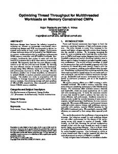
N. V YDYANATHAN , U. C ATALYUREK , T. K URC , P. S ADAYAPPAN AND J. S ALTZ
Technical Report OSU-CISRC-1/07-TR03
An Approach for Optimizing Latency under Throughput Constraints for Application Workflows on Clusters.∗ N. Vydyanathan† , U. Catalyurek‡ , T. Kurc‡ , P. Sadayappan† , J. Saltz‡ † Dept. of Computer Science and Engineering, ‡ Dept. of Biomedical Informatics The Ohio State University
Abstract In many application domains, it is desirable to meet some user-defined performance requirement while minimizing resource usage and optimizing additional performance parameters. For example, application workflows with real-time constraints may have strict throughput requirements and desire a low latency or response-time. The structure of these workflows can be represented as directed acyclic graphs of coarse-grained application tasks with data dependences. In this paper, we develop a novel mapping and scheduling algorithm that minimizes the latency of workflows that act on a stream of input data, while satisfying throughput requirements. The algorithm employs pipelined parallelism and intelligent clustering and replication of tasks to meet throughput requirements. Latency is minimized by exploiting task parallelism and reducing communication overheads. Evaluation using synthetic benchmarks and application task graphs shows that our algorithm 1) consistently meets throughput requirements, even when other existing schemes fail, 2) produces lower-latency schedules, and 3) results in lesser resource usage.
1
Introduction
Complex application workflows can often be modeled as directed acyclic graphs of coarse-grained application components with precedence constraints and data dependences. The quality of execution of these workflows is often gauged by two metrics: latency and throughput. Latency is the time to process an individual data item through all the components of the workflow, while throughput is a measure of the aggregate rate of processing of data. It is often desirable or necessary to meet a user-defined requirement in one metric, while achieving higher performance value in the other metric and minimizing resource usage. Workflows with real-time constraints, for example, can have strict throughput requirements, while interactive query processing may have strict latency constraints. To be able to meet requirements and minimize resource usage is also important especially in settings such as Supercomputer centers where resources (e.g., a compute cluster) have an associated cost and are contended for by multiple clients. ∗
This research was supported in part by the National Science Foundation under Grants #CCF-0342615 and #CNS0403342.
Application workflows, such as those in the fields of image processing, computer vision, signal processing, parallel query processing and scientific computing, act on a stream of input data [10, 4, 18]. Each task or application component repeatedly receives input data items from its predecessor tasks, computes on them, and writes the output to its successors. Since multiple data items can be processed in a parallel or pipelined manner and independent application components can be executed concurrently, the two metrics, latency and throughput, are distinct. In this paper, we present a novel approach for the scheduling of such workflows on clusters of homogeneous processors. Our algorithm employs pipelined, task and data parallelism in an integrated manner to meet strict throughput constraints and minimize latency. The algorithm is designed to satisfy the throughput requirements by leveraging pipelined parallelism and through intelligent clustering and/or replication of tasks. Pipelined parallelism is the concurrent execution of dependent tasks on different instances of the input data stream, while data parallelism is the concurrent processing of multiple data items by replicas of a task. Latency is minimized by exploiting task parallelism, which is the concurrent execution of independent tasks on the same instance of the data stream, and minimizing communication costs along the critical path of the task graph. We compare the proposed approach against two previously proposed schemes: Filter Copy Pipeline (FCP) [14] and EXPERT (EXploiting Pipeline Execution undeR Time constraints) [7]. Evaluations are done using synthetic benchmarks and task graphs derived from real applications in the domains of Image Analysis, Video Processing and Computer Vision [2, 7, 13, 1]. We show that our algorithm is able to 1) consistently meet throughput requirements, even when the other schemes fail, 2) generate schedules with lower latency, and 3) reduce resource usage. This paper is organized as follows. The next section gives an overview of the related work and section 3 describes the task graph and execution model. Section 4 describes the proposed mapping and scheduling algorithm and section 5 describes the experimental results. Section 6 presents our conclusions and outlines possible directions for future research.
2
Related Work
Several researchers have addressed the problem of minimizing the parallel completion time (makespan or latency) of applications in the form of directed acyclic task graphs. As this problem is NP-complete [6], heuristics have been proposed and a good survey of these can be found in [11]. These algorithms typically prioritize the tasks using metrics like bottom-level and schedule the tasks in priority order to processors that allow their earliest start or finish time. Researchers have also proposed the use of pipelined scheduling for maximizing the throughput of applications. Lee et al. [12] proposed a three-step mapping methodology for maximizing the throughput of applications comprising of a sequence of computation stages, each consisting of a set of identical tasks. Jonsson et al. [9] and Hary and Ozguner [8] discussed heuristics for maximizing the throughput of directed acyclic task graphs on multiprocessor systems using point-to-point networks, while Yang [19] presented an approach for resource optimization under throughput constraints. Benoit and Robert [3] have addressed the problem of mapping pipeline skeletons of linear chains of tasks on heterogeneous systems and Suhendra et al. [16] have proposed an integrated approach for task scheduling and scratchpad memory allocation based on integer linear programming for multiprocessor system-on-chip architectures. All of these techniques optimize the throughput metric and do not consider replication of tasks. Though many papers focus on optimizing latency or throughput in isolation, very few address both.
Subhlok and Vondran [15] have proposed a dynamic programming solution for optimizing latency under throughput constraints for applications composed of a chain of data-parallel tasks. In this paper, we target more generic applications that can be modeled as arbitrary directed acyclic task graphs. In [14], Spencer et al. presented the Filter Copy Pipeline (FCP) scheduling algorithm for optimizing latency and throughput of data analysis application DAGs on heterogeneous resources. FCP computes the number of copies of each task that is necessary to meet the aggregate production rate of its predecessors and maps the copies to processors that yield their least completion time. Another closely related work is [7], where Guirado et al. have proposed a task mapping algorithm called EXPERT (EXploiting Pipeline Execution undeR Time constraints) that minimizes latency of streaming applications, while satisfying a given throughput constraint. EXPERT identifies maximal clusters of tasks that can form synchronous stages that meet the throughput constraint and maps tasks in each cluster to the same processor so as to reduce communication overheads and minimize latency.
3
Task Graph and Execution Model
An application workflow can be represented as a connected, weighted directed acyclic graph (DAG), G = (V, E), where V , the set of vertices, represents non-homogeneous sequential application components (tasks) and E, the set of edges, represents precedence constraints and data dependences. There are two distinguished vertices (tasks) in the task graph: the source task which precedes all other tasks and the sink task which succeeds all other tasks. The task graph G acts on a stream of data, where each task in G repeatedly receives input data items from its predecessors, computes on them, and writes the output to its successors. The weight of a vertex (task), ti ∈ V , is its execution time to process a single data item, et(ti ). The weight of an edge ei,j ∈ E, wt(ei,j ) is the communication cost measured as the time taken to transfer a single data item of size di,j between ti and tj . The length of a path in a DAG G is the sum of the weights of the tasks and edges along that path. The critical path of G, denoted by CP (G), is defined as the longest path in G. The top level of a task t in G, denoted by topL(t), is defined as the length of the longest path from the source task to t, excluding the weight of t. The bottom level of a task t in G, denoted by bottomL(t), is defined as the length of the longest path from t to the sink, including the weight of t. Any task t with maximum value of the sum of topL(t) and bottomL(t) belongs to a critical path in G. The task graph is assumed to be executed on a homogeneous fully connected compute cluster, with each compute node having local disks. Our algorithm assumes that the execution behavior of the tasks in the workflow is not strongly dependent on the properties of the input data items. Hence, profiling the workflow on a few sample data items, gives a reasonable measure of the execution times of the constituent tasks. The system model assumes overlap of computation and communication, as most clusters today are equipped with high performance interconnects which provide asynchronous communication calls. The latency of a task graph scheduled on a set of processors is defined as the time taken to process a single data item through it. Let G0 denote the DAG that represents the schedule of task graph G on P processors. G0 can be constructed from G by adding zero-weight pseudo-edges between concurrent tasks in G that are mapped to the same processor. These pseudo-edges denote induced dependences. The latency of this schedule is given by the critical path length of G0 . Let a task-cluster denote the group of all tasks that are mapped to the same processor. Tasks within a task-cluster are run in a sequence in the decreasing order of their bottom-levels and iterate over the
instances of the input stream. Therefore, the time taken by a task-cluster to process a single data item P is given by the sum of the execution times of its constituent tasks, i.e. et(Ci ) = ∀t∈Ci et(t). If the workflow is assumed to act on a stream of independent data items (i.e. processing of each data item is independent of the processing of other data items), multiple copies (replicas) of a task/task-cluster can be executed concurrently. If nr(Ci ) denotes the number of replicas of task-cluster Ci and et(Ci ) is its i) data items per unit time. execution time, the aggregate processing rate of Ci , pr(Ci ) is given by nr(C et(Ci ) Each replica of a task-cluster is assumed to be executed on a separate processor. For example, assume that tasks t1 and t2 are mapped to task-cluster C, and bottomL(t1 ) > bottomL(t2 ) in G0 . Let nr(C) be 2 and let the replicas be mapped to processors P1 and P2 . et(t1 ) = 10 and et(t2 ) = 20. Then, on each of these processors, t1 processes a data item followed by t2 . The processing rate of task-cluster C 2 . is (10+20) 1 data items per unit time, where bwi,j = The data transfer rate of an edge ei,j , dr(ei,j ), is di,j bwi,j
min(nr(ti ), nr(tj )) × bandwidth. Here, bandwidth corresponds to the minimum of disk or memory bandwidth of the system depending on the location of data and the network bandwidth. nr(ti ) denotes the number of replicas of task ti . As we assume that computation and communication can overlap, the overall processing rate or throughput of the workflow is determined by the slowest task-cluster or edge, and is given by min(min∀Ci pr(Ci ), min∀ei,j dr(ei,j )).
4
Workflow Mapping and Scheduling Heuristic
Given a workflow-DAG G, P homogeneous processors and a throughput constraint T , our workflow mapping and scheduling heuristic (WMSH) generates a mapping and schedule of G on P that minimizes the latency while satisfying T . The algorithm consists of three main heuristics, which are executed in sequence: the Satisfy Throughput Heuristic (STH) to meet the user-defined throughput requirements, the Processor Reduction Heuristic (PRH) to ensure the resulting schedule does not require more processors than are available, and the Latency Minimization Heuristic (LMH) to minimize the latency of the workflow. In this section, we describe each of these heuristics. Theorem 1 Given a workflow-DAG G = (V, E) that acts on a stream of independent data items, the maximum achievable throughput Tmax , on P homogeneous processors is given by P P(et(t)) , where t∈V
et(t) is the time taken by task t to process a single data item. Proof The minimum amount of work to be done to process one data item through G is given by P (et(t)). The minimum work to be done per unit time to process Tmax data items is Tmax × Pt∈V t∈V (et(t)). Since, we have atmost P processors in the system and all the tasks can be replicated P as they process a stream of independent data items, P = Tmax × t∈V (et(t)), which implies that Tmax , the maximum achievable throughput is P P(et(t)) . t∈V
Tmax can be achieved by mapping all tasks in G to a single task-cluster and making P replicas, each mapped to a unique processor. However, this mapping suffers from a large latency as it fails to exploit parallelism between concurrent tasks in G. Concurrent tasks refers to independent tasks in G that can be executed concurrently. For the sake of presentation, the rest of this section assumes that G acts on a stream of independent data items and hence all tasks can be replicated. However, the heuristics described
Algorithm 1 STH: Satisfy Throughput Heuristic 1: function STH(G, T ) . G ← workflow DAG, T ← throughput constraint ≤ Tmax 2: S ← schedule of G by priority based list-scheduling 3: L ← Latency of S 4: if L1 ≥ T then 5: return S 6: else 7: Map each task ti ∈ G to a separate task-cluster Ci 8: M ← {Ci | Ci is a task-cluster} 9: if T > 0 then 10: For all Ci , nr(Ci ) ← T × et(Ci ) 11: else 12: For all Ci , nr(Ci ) ← 1 13: E 0 ← {ei,j ∈ G | dr(ei,j ) < T } 14: while E 0 not empty do 15: ei,j is an edge in E 0 16: For all task-pairs (ta , tb ) ∈ clusterOf(ti )×clusterOf(tj ) | ta concurrent to tb in G, add a pseudo-edge in G0 originating from the task with the larger bottom-level. . clusterOf(ti ) is the task-cluster that contains task ti . 17: For all edges ea,b ∈ G | (ta , tb ) ∈ clusterOf(ti )×clusterOf(tj ), wt(ea,b ) ← 0 in G0 18: Merge clusterOf(ti ) and clusterOf(tj ), update M 19: return < G0 , M > here can be applied when processing of a data item is dependent on the processing of certain other data items (i.e replication of tasks is not allowed), by enforcing the weight of every task-cluster to be ≤ T1 , for a given throughput constraint T ≤ Tmax . Tmax in this case, is the reciprocal of the weight of the largest task in G. Algorithm 1 illustrates STH. Given a throughput constraint T ≤ Tmax , STH verifies whether a nonpipelined low latency schedule, generated by priority-based list-scheduling [11], meets the throughput requirement. The tasks in G are prioritized in the decreasing order of their bottom-levels and scheduled in priority order to processors that yield their least completion time. If L is the latency of this schedule, the throughput achieved is L1 . If L1 ≥ T , STH returns this schedule. Otherwise, the following steps are executed to obtain a low-latency pipelined schedule that satisfies T . To generate a pipelined schedule, each task ti ∈ V is mapped to a separate task-cluster Ci . Let the mapping, M denote the set of all the task-clusters. The number of replicas of Ci , nr(Ci ), that is required to satisfy T is computed as nr(Ci ) = T × et(Ci ). When there is no throughput constraint, nr(Ci ) = 1. For all edges ei,j ∈ E, whose data transfer rate is < T , STH avoids the communication overhead by merging the task-clusters containing the incident tasks. When two task-clusters are merged, the DAG G0 representing the new schedule is constructed from G by adding zero weight pseudo-edges between concurrent tasks in G that are now mapped to the same task-cluster. The pseudo-edges originate from the task with the larger bottom-level. Edges between tasks mapped to the same task-cluster have zero weight in G0 . The critical path length of G0 represents the latency of this schedule. For example, figure 1 shows a workflow-DAG
Figure 1. (a) Workflow-DAG G, (b) Modified DAG, G0 with tasks T 1 and T 2 clustered, (c) Modified DAG, G0 with tasks T 1, T 2 and T 3 clustered and pseudo-edge between T 3 and T 2.
G and the resulting modified DAG, G0 that reflects the task-clustering and schedule. Figure 1(a) shows the original workflow-DAG, while in figure 1(b), tasks T 1 and T 2 are mapped to the same task-cluster, hence the edge between them is greyed indicating that it now has zero cost. Figure 1(c) shows T 1, T 2 and T 3 in the same cluster, which results in a pseudo-edge being added from T 3 to T 2, as T 3 is assumed to have a larger bottom-level than T 2 in G0 . Edges between T 1, T 2 and T 1, T 3 are greyed, indicating zero cost. Following STH, PRH is executed. The total number of processors required to execute nr(Ci ) copies P of each task-cluster Ci , where each copy is mapped to a unique processor, is P 0 = Ci ∈M dnr(Ci )e. If P 0 > P , PRH merges certain task-clusters and obtains a schedule that uses ≤ P processors. Once a feasible schedule is obtained, LMH is called to optimize the latency. PRH and LMH output a set of task-clusters and the pipelined schedule is obtained by mapping each replica of a task-cluster to a unique processor. Tasks within a task-cluster are run in the decreasing order of their bottom-levels and iterate over the instances of the data stream. We now present PRH and LMH in greater detail. 4.1
Processor Reduction Heuristic (PRH)
PRH recursively merges pairs of task-clusters based on some metric until we get a mapping that uses ≤ P processors. Theorem 2 If task-clusters Ci and Cj are merged and Pi and Pj are the number of processors required to run the replicas of Ci and Cj respectively, i.e Pi = dnr(Ci )e and Pj = dnr(Cj )e, the number of processors required to run the replicas of the new task-cluster formed that meets the throughput constraint is either Pi + Pj or Pi + Pj − 1. Definition 1 Task-clusters Ci and Cj are “connected” if there exists some task ta in Ci and some task tb in Cj such that ea,b is an edge in G. Definition 2 Task-clusters Ci and Cj are “not concurrent” if for all pairs of tasks (ta , tb ), ta ∈ Ci and tb ∈ Cj , ta is not concurrent to tb in G. Definition 3 Resource wastage of a task-cluster C is defined as dnr(C)e − nr(C).
Algorithm 2 PRH: Processor Reduction Heuristic 1: function PRH(G0 , M ) . G0 ← schedule DAG returned by STH, M ← set of task-clusters returned by STH P 2: P 0 = Ci ∈M (dnr(Ci )e) 3: repeat 4: C 0 ← {(Ci , Cj ) | Ci ∈ M ∧ Cj ∈ M ∧ dnr(Ci ) + nr(Cj )e < (dnr(Ci )e + dnr(Cj )e)} 5: while C 0 not empty ∧(P 0 > P ) do 6: Pick the task-cluster pair (Ci , Cj ) from C 0 that yields the largest decrease in latency when merged. Preference is given to task-clusters that are connected, not concurrent and which produce the largest resource wastage when merged. 7: For all task-pairs (ta , tb ) ∈ Ci × Cj | ta concurrent to tb in G, add a pseudo-edge in G0 originating from the task with the larger bottom-level. 8: For all edges ea,b ∈ G | (ta , tb ) ∈ Ci × Cj , wt(ea,b ) ← 0 in G0 9: Merge Ci and Cj and update M 10: P0 ← P0 − 1 11: Update C 0 12: if P 0 > P then 13: Pick the task-cluster pair (Ci , Cj ) that yields the maximum value of d(nr(Ci ) + nr(Cj ))e − (nr(Ci ) + nr(Cj )) and the largest decrease in latency when Ci and Cj are merged. 14: For all task-pairs (ta , tb ) ∈ Ci × Cj | ta concurrent to tb in G, add a pseudo-edge in G0 originating from the task with the larger bottom-level. 15: For all edges ea,b ∈ G | (ta , tb ) ∈ Ci × Cj , wt(ea,b ) ← 0 in G0 16: Merge Ci and Cj and update M 17: until P 0 ≤ P 18: return < G0 , M > The pseudo code of PRH is illustrated in Algorithm 2. Step 4 of the algorithm considers all pairs of task-clusters that when merged would reduce the number of processors used by 1. Among these, PRH picks the task-cluster pair that yields the largest decrease in latency when merged. To break ties, preference is given to task-clusters that are connected, not concurrent, and which produce the largest resource wastage, in that order (step 6). Merging connected task-clusters helps in avoiding some of the communication costs and merging task-clusters that are not concurrent avoids serializing concurrent tasks in G. Giving preference to task-cluster pairs that yield a larger resource wastage reduces the possibility of fragmentation. Steps 5-11 are repeated as long as there are task-cluster pairs that reduce the processor count and P 0 > P . After all possible task clusterings, if the resource usage is still greater than P at step 12, defragmentation is done in steps 13-16 where the task-clusters that produce the largest resource wastage are merged. To break ties, the one that causes the largest decrease in latency is chosen. The outer-loop (steps 3-17) are repeated until the resource usage is lesser than or equal to P . At the end of the processor reduction phase, a mapping M and schedule G0 is obtained that meets the throughput constraint and uses ≤ P processors.
4.2
Latency Minimization Heuristic (LMH)
LMH is called to refine the mapping obtained by PRH to further optimize the latency. Given a mapping M and schedule G0 which meets the throughput constraint and uses ≤ P processors, LMH optimizes the latency by reducing communication overheads along the critical path. The task-clusters in M are considered by LMH as indivisible macro-tasks. A macro-task therefore, may contain one or more tasks. The incoming and outgoing edges of a macro-task is the union of the incoming and outgoing edges, respectively, of the tasks that it contains, without considering edges between tasks belonging to the macro-task. Hence, the term task in Theorem 3 and Corollary 1 is the same as macro-task in the case where multiple tasks are mapped to same task-cluster by PRH. Theorem 3 Let G0 and M denote a schedule and mapping of G that meets the throughput constraint and uses ≤ P processors. Let ei,j be an edge in G0 from task/macro-task ti to tj such that the indegree(ti ) = in-degree(tj ) = 1 and the out-degree(ti ) = out-degree(tj ) = 1 (i.e. ti and tj are connected along a linear chain in that order). Let tk be the parent of ti and tl be the child of tj . If wt(ei,j ) > wt(ek,i ) + wt(ej,l ), it is optimal to merge ti and tj to a single task-cluster, assuming that all tasks can be replicated. If replication is not allowed, ti and tj can be merged to a single task-cluster only if et(ti ) + et(tj ) ≤ T1 and ei,j satisfies the above condition. Proof Let us assume that in the optimal mapping Mopt that minimizes the latency while meeting the throughput constraint, ti and tj are mapped to different task-clusters. Consider an alternative mapping M 0 , where ti and tj are pulled out from their respective task-clusters and mapped to a new one. Replication ensures that the mapping M 0 meets the throughput constraint. For the case when replication is not allowed, as et(ti )+et(tj ) ≤ T1 , throughput constraint is satisfied. As the replicas of each task/macro-task in M , the mapping generated by PRH (the number of replicas of a task/macro-task is 1 when replication is not allowed) could be run on disjoint subsets of processors using ≤ P processors, by applying theorem 2, any clustering among the tasks/macro-tasks in M will use ≤ P processors and will meet the throughput constraint. Therefore, M 0 uses ≤ P processors and meets the throughput constraint. As ti and tj are mapped to the same task-cluster in M 0 , the length of the longest path through them is reduced by atleast wt(ei,j ) − (wt(ek,i ) + wt(ej,l )). Thus, M 0 always yields lower latency (if ei,j lies on the critical path) or same latency (if ei,j does not lie on the critical path) as Mopt , which contradicts our assumption that Mopt was optimal. Hence, merging ti and tj to a single task-cluster is optimal. Definition 4 The lower bound on the latency of a DAG G is the length of the critical path in G, assuming all edges have zero weights. Definition 5 An edge is non-critical if it cannot lie on a critical path in G. An edge ei,j in G is noncritical if the length of the longest path through ei,j is ≤ the lower bound on the latency of G. Any edge that is not non-critical is called a critical edge. Corollary 1 Let G0 and M denote a schedule and mapping of G that satisfies T and uses ≤ P processors. Let ei,j be an edge in G0 from task/macro-task ti to tj such that all outgoing edges from ti are non-critical except ei,j and all incoming edges to ti are non-critical except ek,i , for some task/macrotask tk . Similarly, all incoming edges to tj are non-critical except ei,j and all outgoing edges from tj are non-critical except ej,l for some task/macro-task tl . If wt(ei,j ) > wt(ek,i ) + wt(ej,l ) and no sub-task of
Algorithm 3 LMH: Latency Minimization Heuristic 1: function LMH(G0 , M ) . G0 ← schedule DAG returned by PRH, M ← mapping returned by PRH. 2: E ∗ ← {ei,j ∈ G0 | ei,j satisfies Theorem 3 or Corollary 1} 3: repeat 4: while E ∗ not empty do 5: ei,j is an edge in E ∗ 6: For all task-pairs (ta , tb ) ∈ clusterOf(ti )×clusterOf(tj ) | ta concurrent to tb in G, add a pseudo-edge in G0 originating from the task with the larger bottom-level. . clusterOf(ti ) is the task-cluster that contains task ti . 7: For all edges ea,b ∈ G | (ta , tb ) ∈ clusterOf(ti )×clusterOf(tj ), wt(ea,b ) ← 0 in G0 8: Merge clusterOf(ti ) and clusterOf(tj ), update M 9: Update E ∗ 10: Pick edge ei,j in CP (G0 ) that does not increase the latency when clusterOf(ti ) and clusterOf(tj ) are merged and has maximum value of min (wt(ei,j ), CP L(G0 ) − LBL(G)) and minimum value of (|criticaledges(ti )| + |critical-edges(tj )|) . CP L(G0 ) ← Critical Path Length of G0 , LBL(G) ← Lower Bound on Latency of G 11: For all task-pairs (ta , tb ) ∈ clusterOf(ti )× clusterOf(tj ) | ta concurrent to tb in G, add a pseudo-edge in G0 originating from the task with the larger bottom-level. 12: For all edges ea,b ∈ G | (ta , tb ) ∈ clusterOf(ti )×clusterOf(tj ), wt(ea,b ) ← 0 in G0 13: Merge clusterOf(ti ) and clusterOf(tj ) and update M 14: Update E ∗ 15: until For all edges ei,j in CP (G0 ), latency increases when clusterOf(ti ) and clusterOf(tj ) are merged 16: return < G0 , M > ti is concurrent to that of tj , it is optimal to merge ti and tj , assuming that all tasks can be replicated. If replication is not allowed, ti and tj can be merged to a single task-cluster only if et(ti ) + et(tj ) ≤ T1 and ei,j satisfies the above condition. Algorithm 3 describes LMH. LMH identifies the set E ∗ of edges that satisfy Theorem 3 or Corollary 1 (step 2) and merges the task-clusters of the incident tasks (steps 6-8). After merging, E ∗ is updated (step 9). Steps 4-9 are repeated until E ∗ is empty. In steps 10-14, among the edges along CP (G0 ) that do not cause an increase in latency when zeroed-in, LMH zeroes-in the edge with the largest maximum possible decrease in latency. To break ties, the edge ei,j with the minimum value of the sum of number of critical edges to ti and number of critical edges to tj is chosen. After merging, E ∗ is updated. The outer-loop of steps 3-15 is repeated until all edges in CP (G0 ) cause an increase in latency when zeroedin. LMH in the worse case takes O(|V | + |E|) steps to choose the set of optimal edges, E ∗ , and O(|V |2 ) steps to merge the incident tasks for each edge in E ∗ . Choosing the best edge in the critical path for zeroin and merging the incident tasks takes O(|V |(|V |2 + |E|). Hence overall, LMH takes O(|V |2 (|V |2 + |E|)) steps in the worst case. In PRH, there are atmost as many task-clusters as tasks and estimating the decrease in latency when two task-clusters are merged takes O(|V |2 + |E|) steps. In the worst case,
all task-clusters are merged (i.e. all tasks are mapped to a single task-cluster and replicated) and hence PRH takes atmost O(|V |2 (|V |2 + |E|)) steps, which is independent of P . Thus, the overall worst case complexity of WMSH is O(|V |2 (|V |2 +|E|)). For small throughput constraints, if WMSH uses prioritybased list scheduling technique to get a low-latency non-pipelined schedule, the worst case complexity is O(|V |P + |E| + |V |log|V |) (O(|V | + |E|) steps to compute the bottom-levels of tasks, O(|V |log|V |) steps to sort them and O(|V |P ) steps to schedule each task in priority order to the best processor).
5
Performance Analysis
This section evaluates the performance of the proposed workflow mapping and scheduling heuristic (WMSH) against previously proposed schemes: Filter Copy Pipeline (FCP) [14] and EXPERT (EXploiting Pipeline Execution undeR Time constraints) [7], and FCP-e and EXPERT-e, modified versions of the above schemes. When FCP and EXPERT fail to utilize all processors and do not meet the throughput requirement T , FCP-e recursively calls FCP on the remaining processors until T is satisfied or all processors are used, while EXPERT-e replicates the task-clusters by dividing the remaining processors among them in the ratio of their weights. The performance of these algorithms is evaluated using both synthetic task graphs and those derived from applications, using simulations. 5.1
Synthetic Task Graphs
The algorithms were evaluated using two sets of synthetic benchmarks: 1) Benchmark-I: a set of randomly generated task graphs with communication delays from [5], and 2) Benchmark-II: synthetic graphs generated using the DAG generation tool in [17]. Benchmark-I comprises of task graphs with 50 tasks each and comparable computation and communication costs. Benchmark-II comprises of 30 synthetic graphs with number of tasks per task graph varying from 10 to 50. The average out-degree and in-degree per task was 4. The computation time of each task was generated as a uniform random variable with mean equal to 30. The communication to computation ratio (CCR) was varied as 0.1, 1 and 10 and the communication cost of an edge was randomly selected from a uniform distribution with mean equal to 30 (the average computation time) times the specified value of CCR. The data volume associated with an edge was determined as the product of the communication cost of the edge and the bandwidth of the underlying network, which was assumed to be a 100 Mbps fast ethernet network. Figure 2 plots the relative performance of the algorithms for benchmark-I on 32 and 64 processors. The x-axis is the throughput constraint, which is decreased from the maximum achievable throughput (Tmax ) in steps of 0.25. ≈ 0 refers to the case when there is no throughput constraint (or negligibly small). The y-axis is the average latency ratio. Latency ratio is the ratio of the latency of the schedule generated by an algorithm to that of WMSH. The missing bars in the graphs indicate that the corresponding algorithm could not meet the throughput requirement. The results show that WMSH is consistently able to generate schedules that meet the throughput constraint. On the other hand, at large throughput requirements (Tmax and 0.75*Tmax ), FCP and EXPERT fail. Though FCP replicates tasks, it computes the number of replicas independent of the number of processors and fails to refine the number of replicas when it maps multiple tasks to the same processor. EXPERT does not replicate tasks. The modified versions are designed to overcome some of these limitations and hence, meet the constraint in some of the cases where FCP or EXPERT fail. With respect to latencies, we find that WMSH generates lower latency schedules than the other
(a)
(b)
Figure 2. Performance on Benchmark-I on (a) 32 processors, (b) 64 processors. The missing bars indicate that the corresponding algorithm could not meet the throughput requirement. T Tmax 0.75*Tmax 0.5*Tmax
WMSH 1 1 1
FCP 0.31 0.41 0.59
(a)
FCP-e 0.35 0.55 1
EXPERT 0.4 0.53 0.8
EXPERT-e 0.68 1 1
T Tmax 0.75*Tmax 0.5*Tmax
WMSH 1 0.91 0.73
FCP 0.93 0.86 0.74
FCP-e 1 1 1
EXPERT 0.49 0.49 0.49
EXPERT-e 0.94 0.94 0.94
(b)
Figure 3. Performance on Benchmark-I on 64 processors (a) Average Throughput Ratio, (b) Average Utilization Ratio
schemes. On 32 processors, FCP generates 27%-29% longer latencies than WMSH, while EXPERT generates 20%-30% longer latencies when throughput constraint is varied from Tmax to 0.25*Tmax . As EXPERT creates maximal task-clusters with weights ≤ T1 , for negligible throughput constraint, it groups all tasks to a single task-cluster and hence generates large latency schedules. For FCP-e, we used the smallest of the latencies of all the workflow instances it creates and hence it is similar to that of FCP. Latency in EXPERT-e is similar to EXPERT, since EXPERT-e only replicates tasks; this improves the throughput but does not alter the latency. As P is increased, Tmax increases, and hence, there are more instances where FCP and EXPERT do not satisfy T . We noticed similar trends at 128 processors. Figure 3(a) shows the average throughput ratio for the schemes for benchmark-I on 64 processors. The throughput ratio is the ratio of the throughput achieved by an algorithm to the throughput constraint. If the achieved throughput is greater than the constraint, the ratio is taken to be 1. We do not show values for throughput constraints lesser than 0.5*Tmax , as all algorithms meet the requirement. We see that when FCP and EXPERT fail to meet the throughput requirement, they generate schedules with throughput atleast 40% and 20% lesser than the constraint, respectively. Figure 3(b) shows the average utilization ratio for the schemes. The utilization ratio is given by the ratio of the number of processors used by an algorithm to the total number of available processors. FCP and EXPERT have low resource utilization, but do not meet the throughput constraint. Among the schemes that generate schedules that meet the throughput requirement, WMSH is able to produce lower-latency schedules while using lesser number of processors. For example, at throughput constraint of 0.5*Tmax , utilization of WMSH is 27% lower than that of FCP-e and 19% lower than EXPERT-e, and it produces latencies 15% and 19% shorter than FCP-e and EXPERT-e respectively. As EXPERT does not replicate tasks, we compared its performance with that of WMSH with replica-
(a)
(b)
Figure 4. (a) Relative Performance of WMSH, WMSH with replication disabled and EXPERT when throughput constraint is max 1 (et(t)) , (b) Performance on Benchmark-II on 32 processors and t∈V CCR=0.1. The missing bars in (b) indicate that the corresponding algorithm could not meet the throughput requirement.
(a)
(b)
Figure 5. Performance on Benchmark-II on 32 processors and (a) CCR=1, (b) CCR=10. The missing bars indicate that the corresponding algorithm could not meet the throughput requirement.
tion disabled. Figure 4(a) shows the performance of WMSH, WMSH with no replication and EXPERT for benchmark-I when the throughput constraint was taken to be the reciprocal of the weight of the largest task in the DAG. We see that even with no replication, WMSH produces lower latencies than EXPERT. WMSH with replication shows the least latency as tasks connected by edges with heavy communication cost can be mapped to the same task-cluster and replicated to meet the throughput constraint. Thus replication not only helps in improving throughput but also minimizing the latency. To study the impact of communication costs, we evaluated the schemes using bench-mark-II by varying the communication to computation ratio (CCR) as 0.1, 1 and 10. Figure 4(b) and 5 show the performance of the schemes as the communication to computation ratio is increased. We find that as CCR increases, there are more instances where FCP, EXPERT and their modified versions do not meet the throughput constraint, while WMSH always does. This is because, WMSH intelligently avoids heavy communication costs, by folding the incident tasks to the same task-cluster and replicating this cluster such that the throughput requirement is met. Though FCP minimizes communication costs in some ca-
pacity by mapping copies of tasks to processors that yield their least completion time, it would still incur the cost when the processor to which the parent task is mapped is heavily loaded (as mapping the task to this processor would cause a larger completion time). EXPERT does not replicate and hence cannot cluster heavy tasks that also have a huge communication cost. The modified versions of the schemes also cannot completely avoid the communication overheads as they only replicate tasks. Similar to benchmark-I, we find that WMSH generates the lowest latency schedules. Please note that the average latency ratios of the modified versions is different from that of the original schemes, since there are some cases where the original schemes do not meet the throughput constraint while the modified versions do. With respect to processor utilization and throughput ratio we see similar trends as for benchmark-I. 5.2
Application Task Graphs
We evaluated the schemes using task graphs from applications in the domains of computer vision, multimedia and medical imaging. We assumed the target system to be a cluster of 2.4 GHz machines connected by a 10 GigE network. The first in this group is a video-based surveillance application [2] that analyzes multiple camera feeds from a region to extract information such that “motion”, or detect suspicious activity. The DAG for this application can be found in [2]. Figure 6 shows the latency ratio and utilization ratio on 32 processors for the video-based surveillance application. We find that when the throughput requirement is large, only WMSH meets the requirement. In cases where FCP and FCP-e meet the constraint, they generate schedules with similar latency as WMSH. As described earlier, when the throughput constraint is negligible, EXPERT and EXPERTe map all tasks to the same task-cluster and hence show a larger latency. With respect to resource utilization, we find that WMSH uses upto 13% lesser processors than the other approaches. Please note that the blanks in the utilization ratio table are for cases where an algorithm does not generate a schedule that satisfies the throughput constraint. Figure 7 shows the performance for the Darpa Vision Benchmark (DVB) [13]. The task graph for DVB is given in [13]. We find that FCP, EXPERT and their modified versions do not meet the throughput requirement T , in many instances. In cases where they satisfy T , WMSH produces schedules with shorter latencies and lower resource utilization than FCP. When T is negligible, the schedule generated by WMSH uses 22% fewer processors than that of FCP and has 4% lower latency. WMSH also produces latencies 15% lower than that of EXPERT. The third application we considered is an MPEG video compression application [7] (results shown in figure 8). Details of the task graph, computation and communication costs are given in [7]. Due to frame encoding dependences, the MPEG frames have to processed in order of arrival. Hence, replication is not possible. We assumed the throughput constraint to be the reciprocal of the weight of the largest task. Though replication is not possible, the input frames can be divided into N segments, that can be processed in parallel. We varied N from 2 to 16 in our experiments. Figure 8 shows the latency and utilization ratio of the MPEG application on 32 processors, as we vary the number of divisions. We find that FCP and WMSH generate schedules with similar latencies, but WMSH has upto 28% lower resource utilization. Though EXPERT shows lower utilization, it generates schedules with 21%-41% longer latencies than WMSH or FCP. We also evaluated the schemes using a workflow from medical imaging - Placenta Workflow [1]. The execution times of the tasks in this workflow was obtained by profiling them on a dual processor Opteron 250 (single core) with 8GB of RAM and 2x250GB SATA disk. The network bandwidth was
T Tmax 0.75*Tmax 0.5*Tmax 0.25*Tmax ≈0
WMSH 1 0.94 0.78 0.53 0.38
FCP 0.91 0.66 0.47
(a)
FCP-e 0.91 0.66 0.47
EXPERT 0.03
EXPERT-e 1 1 1 1
(b)
Figure 6. Performance of Video-Based Surveillance application on 32 processors (a) Latency Ratio, (b) Utilization Ratio. The missing bars in (a) and blanks in (b) indicate that the corresponding algorithm could not meet the throughput requirement
T Tmax 0.75*Tmax 0.5*Tmax 0.25*Tmax ≈0
WMSH 1 0.75 0.53 0.31 0.25
FCP 0.47
(a)
FCP-e 1 0.47
EXPERT 0.03
EXPERT-e 1
(b)
Figure 7. Performance of Darpa Vision Benchmark on 32 processors (a) Latency Ratio, (b) Utilization Ratio. The missing bars in (a) and blanks in (b) indicate that the corresponding algorithm could not meet the throughput requirement
Divisions 2 4 8 16
WMSH 1 1 1 1
(a)
FCP 1 1 1 1
EXPERT 1.21 1.36 1.41 1.24
Divisions 2 4 8 16
WMSH 0.13 0.25 0.5 1
FCP 0.13 0.41 0.78 1
EXPERT 0.09 0.22 0.47 1
(b)
Figure 8. Performance of MPEG video compression on 32 processors (a) Latency Ratio, (b) Utilization Ratio.
T Tmax 0.75*Tmax 0.5*Tmax 0.25*Tmax ≈0
WMSH 1 1 1 1 1
FCP 1 1 1 1
FCP-e 1 1 1 1
EXPERT 1.69
EXPERT-e 1 1 1 1.69
(a)
T Tmax 0.75*Tmax 0.5*Tmax 0.25*Tmax ≈0
WMSH 1 0.91 0.66 0.41 0.13
FCP 1 0.75 0.5 0.28
FCP-e 1 0.75 0.5 0.28
EXPERT 0.03
EXPERT-e 1 1 1 1
(b)
Figure 9. Performance of Placenta workflow on 32 processors (a) Latency Ratio, (b) Utilization Ratio. The missing values indicate that the corresponding algorithm could not meet the throughput requirement
assumed to be 10 Gbps ethernet. Figure 9 shows the performance results. We find similar trends in the performance as for the other applications. FCP and WMSH generated similar latencies, while EXPERT created longer schedules. WMSH uses lesser resources than FCP. In the above experiments, the scheduling time for all the schemes was less than a second suggesting that scheduling is not a time critical operation for these applications.
6
Conclusions and Future Work
This paper presents a mapping and scheduling heuristic for application workflows with stringent performance requirements. The proposed algorithm minimizes the latency of workflows that operate on a stream of data, while satisfying strict throughput requirements. Our algorithm meets the throughput constraints through pipelined parallelism and replication of tasks. Latency is minimized by exploiting task parallelism and reducing communication overheads. Evaluation using synthetic and application task graphs indicate that our heuristic is always guaranteed to meet the throughput requirement and hence can be deployed for scheduling workflows with real-time constraints. Further, it produces lower latency schedules and utilizes lesser resources. Our future work will be focused on 1) scheduling workflows on heterogeneous systems and 2) scheduling workflows where each application component or task is a data parallel program. Acknowledgments We would like to thank Dr. Yves Robert and Dr. Anne Benoit for their valuable discussions and constructive reviews on the paper.
References [1] The placenta image analysis pipeline. http://bmi.osu.edu/∼vijayskumar/placenta1.htm. [2] B. Agarwalla, N. Ahmed, D. Hilley, and U. Ramachandran. Streamline: A Scheduling Heuristic for Streaming Application on the Grid. In MMCN ’06: Proc. of the Multimedia Computing and Networking Conf., 2006. [3] A. Benoit and Y. Robert. Mapping pipeline skeletons onto heterogeneous platforms. Technical Report LIP RR-2006-40, 2006. [4] A. Choudhary, W. Lio, D. Weiner, P. Varshney, R. Linderman, and M. Linderman. Design, implementation and evaluation of parallel pipelined stap on parallel computers. In IPPS ’98: Proc. of the 12th. Intl. Par. Proc. Symp., page 220, 1998.
[5] T. Davidovic and T. G. Crainic. Benchmark-problem instances for static scheduling of task graphs with communication delays on homogeneous multiprocessor systems. Computers & OR, 33(8):2155–2177, Aug 2006. [6] M. R. Garey and D. S. Johnson. Computers and Intractability; A Guide to the Theory of NP-Completeness. W. H. Freeman & Co., New York, NY, USA, 1990. [7] F. Guirado, A.Ripoll, C. Roig, and E. Luque. Optimizing latency under throughput requirements for streaming applications on cluster execution. In Cluster ’05: Proc. of the IEEE Intl. Conf. on Cluster Computing, 2005. [8] S. L. Hary and F. Ozguner. Precedence-constrained task allocation onto point-to-point networks for pipelined execution. IEEE Trans. Par. Distrib. Syst., 10(8):838–851, 1999. [9] J. Jonsson and J. Vasell. Real-time scheduling for pipelined execution of data flow graphs on a realistic multiprocessor architecture. In ICASSP-96: Proc. of the 1996 IEEE International Conference on Acoustics, Speech, and Signal Processing, volume 6, pages 3314–3317, 1996. [10] V. S. Kumar, B. Rutt, T. Kurc, U. Catalyurek, J. Saltz, S. Chow, S. Lamont, and M. Martone. Imaging and visual analysis—large image correction and warping in a cluster environment. In SC ’06: Proc. of the 2006 ACM/IEEE conf. on Supercomputing, page 79, 2006. [11] Y.-K. Kwok and I. Ahmad. Static scheduling algorithms for allocating directed task graphs to multiprocessors. ACM Comput. Surv., 31(4):406–471, 1999. [12] M. Lee, W. Liu, and V. K. Prasanna. A mapping methodology for designing software task pipelines for embedded signal processing. In Proc. of the Workshop on Embedded HPC Systems and Applications of IPPS/SPDP, pages 937–944, 1998. [13] S. B. Shukla and D. P. Agrawal. Scheduling pipelined communication in distributed memory multiprocessors for real-time applications. SIGARCH Comput. Archit. News, 19(3), 1991. [14] M. Spencer, R. Ferreira, M. Beynon, T. Kurc, U. Catalyurek, A. Sussman, and J. Saltz. Executing multiple pipelined data analysis operations in the grid. In SC ’02: Proc. of the 2002 ACM/IEEE conf. on Supercomputing, pages 1–18, 2002. [15] J. Subhlok and G. Vondran. Optimal latency-throughput tradeoffs for data parallel pipelines. In SPAA ’96: Proc. of the 8th ACM Symp. on Par. Algorithms and Arch., pages 62–71, 1996. [16] V. Suhendra, C. Raghavan, and T. Mitra. Integrated scratchpad memory optimization and task scheduling for mpsoc architectures. In CASES ’05: ACM/IEEE International Conference on Compilers, Architecture, and Synthesis for Embedded Systems, Oct 2005. [17] K. Vallerio. Task graphs for free. http://ziyang.ece.northwestern.edu/tgff/maindoc.pdf (2003). [18] M. Yang, T. Gandhi, R. Kasturi, L. Coraror, O. Camps, and J. McCandless. Real-time obstacle detection system for high speed civil transport supersonic aircraft. In Proc. of the IEEE National Aerospace and Electronics Conf., pages 595–601, 2000. [19] M.-T. Yang, R. Kasturi, and A. Sivasubramaniam. A pipeline-based approach for scheduling video processing algorithms on now. IEEE Trans. Par. Distrib. Syst., 14(2):119–130, 2003.