An Approach to the Synchronization of Backup Masters in Dynamic Master-Slave Systems Ernesto Martins, Joaquim Ferreira, Luís Almeida, Paulo Pedreiras, José A. Fonseca DET – IEETA, Universidade de Aveiro Aveiro, Portugal
[email protected],
[email protected],
[email protected],
[email protected],
[email protected] Abstract This paper considers the case in which master-slave fieldbus networks are used in safety-critical embedded applications, such as transportation systems. The communication in these networks is controlled by the master that contains a cyclic traffic dispatching table. Master replication is used to achieve fault-tolerance. Traditional approaches to system design, also due to faulttolerance reasons, have considered static tables, only. However, there is a growing demand for flexibility, mainly to improve the efficiency in using system resources. This calls for the replacement of such static tables with dynamic tables, containing the current communication requirements, and for on-line traffic scheduling. This paper considers such dynamic master-slave architectures and addresses the problem of synchronizing the active and backup masters. In particular, the master node uses a scheduling co-processor to speed up the traffic on-line scheduling and schedulability analysis, as well as to achieve synchronization in a short period of time.
1. Introduction Many safety-critical embedded systems used today, e.g. in transportation systems, are distributed and rely on a fieldbus network that interconnects sensors, actuators and controllers in a reliable and timely way. One popular network access control paradigm that is used in many of these applications is the master-slave paradigm, in which a single node controls the traffic on the bus using a cyclic traffic dispatching table. Several examples can be pointed out, such as WorldFIP [5] and TCN [6], largely used in train control systems, as well as MIL-STD-1553B [4], which has been used for a long time in the USA, for distributed hard-real time applications. Master replication is, of course, essential to avoid the single point-of-failure and achieve fault-tolerance. Master-slave networks are naturally synchronized with the master since this node explicitly tells each slave when to transmit. The main advantage of this type of networks when it comes to increasing operational flexibility, to allow on-line changes to traffic parameters, is that such parameters are concentrated on the master node, only. This simplifies the admission control of change requests and reduces the respective reaction time with respect to distributed alternatives. With this type of flexibility, one can turn on and off the transmission of message streams, or vary the
respective transmission rates, according to the run-time needs of the system. This results in a higher efficiency of network utilization, freeing bandwidth that can be used to serve more streams or to facilitate error recovery. However, when replicating the master node, the fact that table contents can vary on-line increases the difficulty in assuring the synchronization between active and backup masters. In this paper, a synchronization mechanism is shown, which improves previous work [7] by taking advantage of a scheduling co-processor (MESSAgE) [2] that assists the master nodes. This mechanism is applied to Controller Area Network (CAN) using FTT-CAN [9].
2. Problem statement Master-slave protocols are considered as exhibiting a single point-of-failure. This, of course, is no longer true when the master is replicated so that upon failure of the active master, a backup enters into action within a sufficiently short interval. It is necessary, however, that the masters fail in a silent way and that they are synchronized with respect to the scanning of the traffic dispatching tables, which are normally organized as a succession of so called micro-cycles. In our work, the static traffic dispatching table is replaced by a dynamic table containing the communication requirements, i.e. properties of the message streams such as period, phasing, transmission time. This table is then scanned on-line by a traffic scheduler. In this case, there is no longer the concept of a cycle count relative to a fixed referential such as the top of a dispatch table. Thus, other mechanisms must be used to enforce synchronization between active and backup masters. Furthermore, there is now a problem of coherency between the multiple instances of the dynamic table. There maybe change requests that, due to asynchronous start/restart of a master or omission communication faults, are taken by the active master but not by one or more backups, or vice-versa. When this happens, it is important to reestablish coherency and synchronization among all masters as fast as possible. This is the specific problem addressed in this paper. Further work is being carried out at the level of the protocol between the client that issues the change request and the masters, i.e. servers. Particularly, it is important to deal with the incoherencies that might arise from omissions in the change requests so that such situations are detected
as early as possible and the consequent resynchronization initiated promptly. A preliminary protocol has been proposed in [7] which is light and allows a fast response to the client but, on the other hand, is relatively slow in detecting loss of synchronization. Other existing protocols involving passive or semi-active replication [3], particularly those developed specifically to support faulttolerant broadcasts in CAN [1][8] are currently being considered.
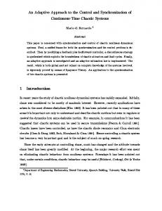
3.2. MESSAgE Coprocessor The coprocessor is capable of scheduling up to 32 messages according to one of three selectable criteria: rate monotonic, deadline monotonic or general priority-based. Its functionality is best understood by considering Figure 1 which illustrates its programming model, as seen by the node CPU. MPRS31
3. Target architecture As referred before, we tested our approach on an FTTCAN system [9]. However, the same approach is applicable in any Master-slave network that allows runtime swapping of traffic dispatching tables, supports periodic and aperiodic messages and includes a master replication scheme with detection of active master failure and backup election. All these are common features for example in WorldFIP. In the case of FTT-CAN it is important to refer that it is based on a cyclic framework in which bus time is broken in consecutive fixed duration cycles called Elementary Cycles or ECs. Each EC is triggered by a special message called Trigger Message. This message not only triggers the start of a new EC but also carries the so-called ECschedule, which is the list of messages that must be produced (transmitted) in the respective EC. The slave nodes that are producers of the specified messages transmit them. Collisions at bus access within the EC are sorted out by the native MAC of CAN. The fact that only one master message is sent per EC dramatically improves the bandwidth efficiency of the protocol with respect to a conventional Master-slave access control. The protocol also supports synchronous (periodic) and asynchronous (aperiodic) traffic within two disjoint windows in the EC. Only the synchronous traffic is scheduled by the master. Finally, the synchronous communication requirements are stored in a table called Synchronous Requirements Table or SRT. On-line changes to the SRT go through an admission control that accepts them only if the overall traffic schedulability is guaranteed.
3.1. Master node architecture In FTT-CAN all master nodes can be equipped with a microcontroller and a MESSAgE coprocessor. In this case, the coprocessor works as a slave of the node CPU, taking care of message scheduling and schedulability analysis, while the CPU is responsible for dispatching, admission control and node management. The coprocessor schedules synchronous traffic on an EC basis, generating EC-schedules. Between the generations of successive EC-schedules the node CPU can change the message parameters inside the coprocessor, as well as add to or delete messages from the set.
MPRS 2 MPRS 1 MPRS0 DurReg0 PriReg0 PerReg0 DeaReg0 PhaReg0
32 Message Parameters Register Slots
EC-Schedule Register (32)
Control / Status Register (8) G/D SA NS AS INT NIT SP1 SP0 Message State Register (32)
Figure 1 - MESSAgE programming model.
Each message to be scheduled is assigned to one of the 32 available Message Parameters Register Slots (MPRSs). Each MPRS holds five, 8-bit parameters which characterize the message. The message schedules produced by the coprocessor are made available on the 32-bit ECSchedule Register (ECSReg). The schedules are for an entire EC, and are thus called EC-schedules. Each message allocated in a given EC is specified by a “1” in the bit position corresponding to its MPRS. In this way, bit number i corresponds to the message assigned to MPRSi. The Control and Status Register (CSReg) is used to control the coprocessor in scheduler or analyzer modes, and to check its status. The Message State Register (MSReg) includes a bit flag for each MPRS, which indicates if the corresponding message has already been release but was not yet scheduled (it is delayed). This information can be read to check the scheduler state, or written to force a particular state. MSReg is used on the master’s synchronization protocol, allowing the state of the active master’s coprocessor to be copied to the coprocessors in the backup masters. In its current FPGA-based implementation, MESSAgE runs at a maximum clock rate of 24MHz, which allows it to generate an EC-schedule in at most 25µs. This is about two orders of magnitude less than any real-world EC duration (1-10ms), which leaves virtually all the time for schedulability tests. As we shall see, this fast scheduling time is also fundamental in the masters’ synchronization protocol.
4. Synchronization Backup Masters
between
Active
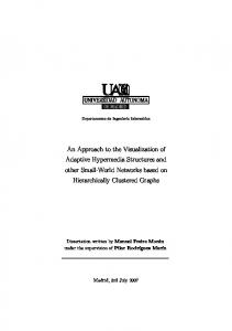
The timeline of the synchronization process is depicted in figure 2. It begins with a backup master issuing a synchronization request (MST_DATA_QRY message) to the active master. This causes the latter to download the scheduling data in two rounds. The first round comprises the transmission of the static portion of the data. This data is packed in a set of CAN messages and transmitted in the asynchronous windows of a number of ECs. In the second round the active master transmits the dynamic portion of the scheduling data. This comprises the instantaneous phases of all messages and their respective state. Because this transmission may span more than one EC, the data actually sent to the backup master is a snapshot of the phases and message states captured by the node CPU on the coprocessor, just before the start of this round. At the end of this transmission the active master sends a special message containing the dynamic data transfer interval (DDTI), which is the count of the number of elapsed ECs since the coprocessor state was captured. This number tells the backup master the scheduling delay (in ECs) relative to the active master. Since the coprocessor in the backup master is now updated with the scheduling data just received, the node CPU just needs to command its coprocessor to generate that number of consecutive ECschedules (fast-forward). After that, the backup master is synchronized. Note in Figure 2 that the backup master synchronizes only one EC after the reception of the DDTI message. This is to guarantee that the backup master has enough time (at least one EC long) to generate the required number of ECschedules specified in the DDTI message even when this message arrives late in the EC. Since we expect DDTIs of just a few ECs (because the dynamic portion of the scheduling data can be packed in a
and
Backup masters are used to guarantee the automatic substitution of the active master, once an EC trigger message is missed. They continuously monitor the network looking for EC trigger messages. If the next trigger message is delayed more than a given tolerance, the active master is assumed to be defective and an election mechanism decides which among the backup masters transmits the missing trigger message. The elected backup becomes the new active master. Clearly this requires that all backup masters be synchronized with the active master. In other words, backup masters must be working in lock-step with the active master, producing the exact same EC-schedules at all times. Some events, however, can place backup masters out of synch. For example a master can be restarted by a watchdog timer, causing its scheduling state information to be lost. Also, a change in the SRT may not be communicated in time to the backup masters, causing them to detect an inconsistency between the next ECschedule they receive and the one they have produced. In these cases some backup masters may need to resynchronize.
4.1 Synchronization Protocol The synchronization protocol between masters involves, basically, the transmission of the SRT as well as the coprocessor scheduling state from the active to the backup masters requesting synchronization. This data transfer is carried out using high-priority asynchronous messages. ACTIVE MASTER EC1
EC2
ECS-1
ECS
EC-schedule for ECS+2 completed
ECS+1
ECS+2
Coprocessor state captured
ECS+D
ECS+D+1
DDTI = D, sent is to backup
BACKUP MASTER
Static data transfer
Scheduling inconsistency detected
Dynamic data transfer
(MST_DATA_MSGPROP)
(MST_DATA_SCHINF) RSP
Synchronization request (MST_DATA_QRY)
TX trigger message
Backup 'fastforwards' D+1 EC-schedules
Backup is synchronized
RX trigger message
Figure 2 – Master synchronization protocol timeline.
few CAN messages - see next section) and given the high scheduling speed of the coprocessor (0.5% of a 5ms EC), it is reasonable to assume that backup masters can achieve synchronization one EC after they receive the DDTI message.
4.2 Worst-case Synchronization Time In order to assess system reliability it is important to determine the time taken by the synchronization process described previously, since during that interval the backup master is unable to replace the current active master. The number of CAN messages required to send all scheduling data, depends on the size of the SRT. However, since we are interested in computing the worst-case synchronization time we shall assume here that coprocessors are being used at their full capacity, i.e. with 32 messages. Since the static scheduling data comprises 5 bytes per message, for a total of 128 bytes, the static data transfer can be carried out using 16 maximum length (8 bytes) CAN messages. The dynamic data is made of 36 bytes (32 phases plus the 32 bits of the MSReg register), so it can be transmitted in 5 CAN messages (four with 8 bytes, one with 4 bytes). Apart from these data frames the synchronization process includes also the synchronization request message and the final DDTI message. The worst-case synchronization time can be stated as STWC = RSP + 2.LEC
(1)
where RSP is the response time of the DDTI message, measured from the point where the synchronization request is issued by the backup master (Figure 2), and LEC stands for the EC duration. The FTT-CAN protocol supports asynchronous messages with bounded response times. Given the set of asynchronous messages exchanged during the synchronization sequence, their relative priorities and the minimum bandwidth reserved for the asynchronous window, it is possible to compute an upper bound for RSP [9]. As an example, consider a bus transmission rate of 500Kbit/s, an EC of 5ms and a minimum asynchronous window of 2.5ms. For the worst-case number of messages as referred before, RSP can be upper bounded by 3 ECs using the response time analysis presented in [9], resulting in an upper bound for STWC of 5 ECs. This is about one order of magnitude faster than our previous synchronization scheme [7].
5. Conclusions This paper addressed the problem of synchronizing backup masters in dynamic master-slave architectures. Since the traffic description tables used by the masters in
such architectures are dynamic, it is fundamental to assure that backups remain synchronized with the active master, even if temporarily they loose synchrony. This might happen due to asynchronous start/restart or due to omissions in broadcasting the change requests among the masters. This paper proposes a synchronization protocol that takes advantage of a scheduling co-processor to achieve a relatively fast synchronization, improving a previous approach proposed by the authors. The approach is applied to an FTT-CAN system and illustrative worstcase figures are shown. However, it is applicable to any master-slave network that allows run-time swapping of traffic dispatching tables, supports periodic and aperiodic messages and includes a master replication scheme with detection of active master failure and backup election (e.g. WorldFIP). Further work is being developed at the level of the protocol between the clients that issue change requests and the active master in order to achieve a prompt detection of unsynchronized backup masters.
6. References [1] L. Pinho, F. Vasques, Timing Analysis of Reliable RealTime Communication in CAN Networks, in Proceedings of Euromicro Conference on Real-Time Systems (ECRTS 2001), pages 103-112, Delft, Netherlands, June 2001. [2] Ernesto Martins, José Alberto Fonseca, Luis Almeida, A Coprocessor for Traffic Scheduling and Schedulability Analysis in FTT-CAN, Proceedings of the 8th International CAN Conference, Las Vegas, USA, February 26/28, 2002, pp.6-8 to 6-15. [3] F. Pedone, M. Wiesmann, A. Schiper, B Kemme, G. Alonso, Understanding Replication in Databases and Distributed Systems, in Proceedings of International Conference on Distributed Computing Systems, pages 464474, 2000. [4] Haverty, N. (1986). MIL-STD 1553 – a standard for data communications. Communication & Broadcasting, 10(1): 2933. [5] IEC International Standard 61158: Fieldbus standard for use in industrial control systems – Type 7: WorldFIP; IEC, Int. Electrotechnical Committee, 2000. [6] IEC International Standard 61375-1 Electric railway equipment - Train bus - Part 1: Train Communication network, 1999. [7] J. Ferreira, P, Pedreiras, L. Almeida, J. Fonseca, Achieving fault tolerance in FTT-CAN, in proceedings of the Workshop on Factory Communication Systems (WFCS 2002), Västerås, Sweden, 2002. [8] J. Rufino, P. Veríssimo, G. Arroz, C. Almeida and L. Rodrigues, Fault-Tolerant Broadcasts in CAN. In Proc. of the 28th Symp. on Fault-Tolerant Computing, Munich, Germany, pp. 150-159. [9] L. Almeida, P. Pedreiras, J. A. Fonseca, The FTT-CAN Protocol: Why and How, IEEE Transactions on Industrial Electronics, vol. 49, no. 6, December 2002 (to appear).