ACTA M E C H A N I C A
Acta 5~echanica 28, 55--64 (1977)
@ by Springer-Verlag 1977
An Approximate Technique for Evaluating the Closures Due to Mining By R. Jones~ J o h a n n e s b u r g , a n d J. Xenophantos~ H a w t h o r n , V i c t o r i a With 5 Figures
(Received June 8, 1976) S u m m a r y - Zusammenfassung An Approximate Technique for Evaluating the Closures Due to Mining. A modified form of the Kerr foundation model is used to obtain closed form analytical expressions for the closure between opposing points in the roof and the floor of a mining excavation. The results are found to closely agree with both a finite element analysis, and also with experimentally determined data. Eine • fiir die Absch~itzung des Versehlieilens im Bergbau. Eine modifizierte Form des Kerrschen Griindungsmodells wird verwendet, um einen geschlossenen analytischen Ausdruck fiir das Verschliel?en zwisehen entgegengesetzten Punkten der Decke und des Bodens eines Bergwerksehaehtes zu erhalten. Die Ergebnisse stimmen gut mit einer Finite-Element-3/Iethode und ebenso mit experimentell ermittelten Daten iiberein.
1. Introduction
A number of attempts have been made to describe the deformations in a mining excavation. Generally the excavation is treated as a crack acted upon by equal and opposite forces on either side of the discontinuity. The solution to this problem, in the case of an infinitely deep rock mass, then follows from some general results on cracks given by Mnshkelishvili [I]. Another method which is widely used is that proposed by Starfield et al [2], [3], [4] which treates the problemas a plane strain problem. The finite element method has also been used [6], and is particularly useful in the case of a layered rock mass of finite depth. An interesting and more comprehensive survey of this subject is presented by Berry [5]. The present paper tackles the problem using the modified Vlasov method, which has been shown by the authors [7] to yield the Kerr foundation model [8], [9] as a special case. The advantage of this approach is that it yields closed form solutions for the closures in the excavation. The obtained closures are then compared with a finite element solution and also with experimentally obtained data. In both cases the agreement is very good and is sufficiently accurate for most engineering purposes.
56
I~. Jones and J. Xenophantos: 2. The Model
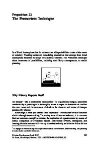
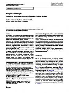
Consider a thin elastic isotropic layer of thickness 2h, lying in a second elastic isotropic material at a distance h2 beneath the surface and at a distance h3 above a rigid base. The Youngs modulus and Poisson's ratio of the containing material and the thin seam are E2,s, v2,s and E1 s ul,~ respectively. A portion of the seam of length 2a has been removed, and a load p is considered to be acting on either side of the excavation, or cut (see Fig. 1). upper surface
h2
2hl.~/thii
containing material
~'=2a p ~i
,
; & i J 9 xz ~
h3 ////.,
excavation
containing material
0 ]p
,,
"txz=O
I
t l z
///////////////////////////////,
rigid base
Fig. 1 Let us take our coordinate system with the z axis directed positively downwards, the oxy plane bisection the thin seam and the origon of the coordinate system half way along the cut (see Fig. 1). Since the seam is thin we m a y assume as in [10], that, in the seam, away from the oxy plane the vertical deformation profile is linear. In the upper and lower portions of the containing material we assume, again in accordance with Vlasov [10], that the vertical deformation profile takes the form of a hyperbolic function. Furthermore we will require the model to reduce to the Kerr two layer foundation model in the limiting case when the upper layer vanishes, i.e. h2 -+ 0, and when the excavation is no longer present, i.e. a --> 0. Outside the excavation the deformations must naturally be continuous. However for IxL< a the vertical displacement must be discontinuous, since in the case of a cut of negligable thickness the roof and the floor of the excavation are thought, [5], to deform in different ways. In addition to this the upper surface must be stress free while the displacement w(x, z) must vanish on the lower rigid base. These assumptions can be satisfied by seeking the vertical deformation w(x, z) in the form W(X, Z) =
Wl(X) 41(Z) @ W2(X) 42(Z) -~- W3(X) 43(Z),
(1)
where the functions 41, 42, and 43 are given in Table 1, and where in order to satisfy the contimdty conditions we require
w3(x) =w2(x)
for
Ixl > a .
(2)
Approximate Technique for Evaluating the Closures Due to Mining
57
Table 1
h~ ~ z
0 ~ z --~ h 1
--h 1 --< z ~ 0
z g --h 1
r
0 0
h1 + z hi 1
0
~e
h I -- z hi 0
~b3
sinh y3(H3 -- z) sinh y3H3
1
0
cosh y~(H~ + z) cosh y2H~ 0
Thus in the region IxI > a the expression for w(x, z) simplifies to w(x, z) = wl(x) el(Z) + we(x) r
(3)
where ~b4(z) = Cs(z)
when
z ~ 0,
---- Ce(z)
when
z ~ 0.
(4)
W h e n h -> 0, and the upper layer vanishes, then this model reduces to the Kerr foundation model, [8], as described in [7]. The constants Y2 and Ya m a y be interpreted as soil parameters and either measured experimentally or obtained from k n o w n elastic solutions. I n the region Ix] G a the function we(x) m a y be interpreted as the vertical m o v e m e n t of the ceiling of the excavation, while the function w3(X) represents the vertical m o v e m e n t of the floor of the excavation. Since the loads applied to the cut act only in the vertical direction we m a y assume t h a t the horizontal displacements u and v are negligable in comparison with the vertical displacement w(x, z). L e t us now consider the region Ix[ > a. E q u a t i n g to zero the work done b y all the external and internal forces; due to a virtual displacement (~w ( = 5w1r + 3w2r results in the following expressions H~
H3
-~
r
d~
(5)
~dz=O
(6)
dZ--
--H~
~
--H2
and //a
H3
~x --H~
r
dz---H~
where H8 = h~ + hi, H2 = h2 + hi. Substituting the well k n o w n expressions for the stresses a~. and Tx~ in terms of the displacement w(x, z) results in the following two ordinary differential equations, viz
d2Wl
d2w2 G2rle - - w 1 ElSll - - O, dx 2" Glrn + ---~dx --~1-2 1
(7)
and d2wl dew2 dx 2 Girl2 -r dx-----~ (Glr2~ + Gr
wuE2s~"~ - - O. (1 - ~2)
(s)
58
R. Jones and J. Xe~_ophantos:
Here hi
/ c~i~dz
rtl =
hi
= --'~-,
/
r~2 =
-hi
r
.,
--h~
/
Ha
~ hi
/
4,4'~ dz +
hi
--
+ 2 dz =
',
7~@ 4>~ + -5- 4'ta,
--hl
h,
r
(9)
Ha
H~
where 4t2, r
+~'~dz=--[
s.=
--h~
~-~2 =
dz = 2h i,
~ll
hl
q~=
r
--h~
-- H~.
h~
t~a '
and qb,,
,aha -- y.~ha) 2ya sinh =yaha (sinh yaha cosh -/aha -k yaha} 2 sinh =7aha
~bl~a -= 7a
Similarly applying the principle of virtual work to the regime's above and below the cut, for which Ix[ =< a , yields the following differential equations for the m o v e m e n t of the upper and lower surfaces of the excavation, viz (~2W2
k~w2 - - 2t2
dx---~ =
p
(11 )
and kaW a
-
2~a d'2wa
-
(12)
dx ~
p
t~ =
E2
where k z --:
E2h2
'
,
(13) __
~
-
Eeha
E2
(l - "0~i r
~
= ~2~( t + "0~)
~)t2 9
Here as in Vlasov the moduli E~, El, 92, and Vl are related to the actual moduli of the soil E~,, Els, v~s and h , b y the formulae E2s
Els 2
'
E1 =-
(:,.4) 'Vi:" --= ~
"023 ,
1 - - V~.s
"PI8
7)1 ~ -
1
-
-
hs
Approximate Technique for Evaluating the Closures Due to 5'Iining
59
Since the seam is considered to be very thin in comparison with the total thickness 2h~ -~ h2 -~ ha, of the foundation then Eqs. (7) and (8) m a y be simplified, as in [7] and [10], b y neglecting terms of order hi and smaller to obtain 2E1
(1
-
-
~12) h1
wl = 0,
(15)
and 2(4 ~- 4) ~d~w2 dx __ (]~2 + 4 )
w2 = 0.
(~6)
F r o m which we obtain w~ = 0,
(17)
w2 = A l e - ~ + A2e+a%
(18)
and
where ~ =
(~ T2t3i
and A1, A2 are two arbitrary constants which are to
be found from the b o u n d a r y condition at infinity, viz. w~ = 0
at
x = •
(19)
and the fact t h a t the vertical edges of the excavation are stress free, i.e. Txz
Gdw[=G~~ = ~ ~x
on
IxJ=a
and
,~r a Eq. (19) requires As : 0,
(21)
while in order to satisfy Eq. (20) we require A~ = 0,
(22)
so t h a t we obtain W1 =
W2 ( =
WS) =
for
0
Ix] > a.
(23)
Since the displacements w~ and w8 m u s t be continuous at the edges of the excavation, Eqs. (11) and (12) m a y now be solved for w2 and Wa subject to the edge conditions we = wa = 0 at Ix[ = a. (24) This gives
P [1
c~
w~ = T~.
cosh ~ ] '
(25)
and w8 --
P [1
k3
oosh~]
eosh ~ a J '
(26)
where
-IX and
(28)
60
1~. Jones and J. Xenophantos:
so t h a t the closure 6(x), is given b y ~(x) = w~(z) -
wdx)
=p [-~ [1 y~
I [i
eosh a2aj
c~
-}--~
(29)
cosh aagJJ"
I t is interesting to note t h a t this model predicts t h a t the floor of the e x c a v a t i o n will m o v e up while the roof moves down. Such a behaviour is found in practice. L e t us now examine several special eases.
Case (1): H2 and H8 are infinite. I n this case we proceed as suggested b y Y a n g [19] and Vlasov [10], taking
4~ = e-y~,
(30)
4~ = e~Z,
(31)
and where y takes the value V --
1.5
(32)
This gives k3 =/c2 = / c -- -
.75E
(1 - ~2)a ,
(33)
-
E6~
2t3 = 2t2 = 2t = -------~'6(1 ) v+
(34)
and ~r
1 " 5 W i 2-
v'
(35)
and where from here onwards we drop the subscript 2 calling v2 = v and E2 = E . We now obtain
~(x)
(36)
[
which has as its m a x i m u m value -
4(1L;-~
p~
/-y-
[1 -- 1/cosh (1.5 [/1--Z~)]
(37)
occuring at x = 0.
Case (2): Let us now assume t h a t the lower layer is still infinite, but the upper layer is thin, i.e. h2 is small. Since in a thin layer the vertical deformation profile is linear, see Vlasov [10] then ~2(z) takes the form 62(z) = cl + c~z,
(38)
Approximate Technique for Evaluating the Closures Due to Mining
61
where G1 a n d c~ are constants. (A l i m i t e d e x p e r i m e n t a l i n v e s t i g a t i o n into t h e Vlasov a s s u m p t i o n s is r e p o r t e d in t h e a p p e n d i x . ) H o w e v e r since t h e r e is no v e r t i c a l l o a d on t h e u p p e r e x t e r n a l surface z = - - H 2 , we require ~lz=-~
E (1 - v2) W2~2'l~=_H~ = 0
--
(39)
a n d from which we see t h a t qb2 m u s t be a c o n s t a n t . As before we set 42 = 1 on z = - - h i , giving qb2(z) = 1 for all z __< 0 a n d c o n s e q u e n t l y (40)
h2E
/c2 = O,
2t2 - - 2(1 -t- v)"
So t h a t t h e differential e q u a t i o n for w2 becomes h2E
d2w
2(1 + v) dx 2 - - p '
(41)
giving 2p(1 + v)
w~ -
-
-
h2E
(~2 _
(42)
x~).
T h e closure now t a k e s t h e form
! ~(x) -
~
oo~h
(,.~ ~
-
~)
J ~
~(1 - x~/~:)|, h2(1 -- v) +
J
(43)
a n d a t x = 0 t h e closure o b t a i n s t h e m a x i m u m v a l u e : viz a
-
-7-: e o s h 1.5
h2(1 - - v)
(44)
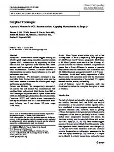
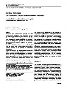
F r o m case (1) we see t h a t when t h e e x c a v a t i o n lies a t considerable d e p t h b e n e a t h t h e surface t h e n t h e closure d e p e n d s l i n e a r l y u p o n t h e l e n g t h of t h e e x c a v a t i o n , i . e . a . H o w e v e r when t h e e x c a v a t i o n is closer to t h e surface, as in ease (2), t h e n t h e closure varies q u a d r a t i c l y w i t h t h e l e n g t h of e x c a v a t i o n . I n order to j u d g e t h e degree of a c c u r a c y of t h e solution let us consider t h e ease when E28 = 106p.s.i. a n d u2s = .2, a n d p = 363p.s.i. The solution o b t a i n e d b y this m e t h o d is given in Fig. 2 along w i t h a finite element, g i v e n in [6] for t h e same p r o b l e m . A f u r t h e r e s t i m a t e of t h e a c c u r a c y m a y be o b t a i n e d b y considering t h e f o u n d a t i o n , cons!sting of t h e l a y e r e d rock mass as shown in Fig. 3. I n order to a n a l y z e t h e p r o b l e m we first replace t h e l a y e r e d f o u n d a t i o n b y an e q u i v a l e n t f o u n d a t i o n w i t h a v e r a g e d modulii E2~, u2s where E2s = (Elh! q- E~h2 + Eah8 q- E4h4)
(hi + h2 + ha + h~)
(45)
= 4.01 9 106 p.s.i, and P28
(vlh1 + v2h~ + yah3 q- v4h~) (hi + h2 + ha +, h4) = .232.
(46)
62
1~. Jones and J. Xenophantos:
Here the values E i, ~i (i ~- 1.4) for the four layers are as given in Fig. 3. The closure's thus obtained are also shown in Fig. 2 along with experimentally measured closures, as given in [6]. The agreement between the present approximate analysis with the measured data, and also with the finite element analysis, is remarkable.
1
~2 c
" " = = ~ ~ X ~ x - - p r e d i c t e d pr~ . , . . . . ~ ~ ' " ~ - ~ _ method ~"~_~ ~
" --'-
closures for the layered - -*---~ rock mass
~ ~
E=,0'p.
"
"*"~
" -
E to 4 o~5 \'\finite
o
E6 E
37 E8
~
E=106 p.s.i. I
100
I
200
I
I
300 400 total [ength of cut,
I
500
!x faiture 600 ft
Fig. 2
sandstone E~=10%.s.i. "v1=.2
dole,ite
E2=I01p.s.i. ,,'2=.2
Sandstone E3=106p.s.i. "~3=.2
1 = 122 ft
h2= I 0 7 f t
h3= 30 ft
shale EL=.3xl06p.s.i. "~4=.:4 /excavation Ih = 49ft &6a[; s'e"ah'i V / / / . / / / / / / / / / ~ / F///////////////,,/~
Fig. 3 3. Conclusion
A simple approximate method for calculating the closure's in a mining excavation has been presented. This technique, based upon both the Kerr and Vlasov foundation models, yields simple closed form analytical solutions for the closure and is seen to be sufficiently accurate for most engineering purposes. 4. Appendix
A limited experimental investigation was undertaken to investigate Vlasov's assumptions. A sheet of gum rubber was used to simulate an elastic foundation, material. This material was chosen mainly because of the limited finance available,
Approximate Technique for Evaluating the Closures Due to Mining
63
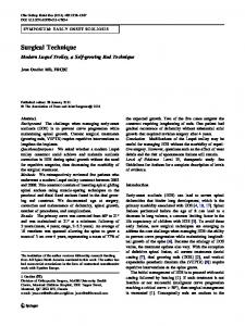
but also because of its low Young's modulus (approximately 1000 K N / m 2) and because the properties of the rubber were easily obtained. Poisson's ration, v, was found to be 0.48. For simplicity a two dimensional model was tested. The load was transmitted to the foundation via rigid beams of the same width as the foundation. Five beams of length 12.5 ram, 25 ram, 37.5 ram, 50 ram, and 75 mm were tested, the depth H of the foundation being 150 m while the thickness of the foundation is 6.25 ram. Particulars of the testing apparatus are given in Fig. 4. The deformations were measured at various points beneath the point of application of the load, and were measured using a travelling microscope to within an accuracy of 0.001 ram. P
P
I
, 225 mm
,
rgU~e ~ S//J~u-~450
mm
~////////~///////////~//////~/~
,FA
I
r L_J
Rigid Support
I1~1 12.5 mm
Fig. 4. Geometry os the test apparatus The vertical deformation w(x, z) for this experiment is predicted by Vlasov [10] to take the form w(x, z) = w(x) ~(~) (i) where r the form
is termed the vertical deformation profile and is thought [10] to have ~(z)
sinh y(H -- z) sinh ~H
4c_ 6a-
(ii)
c_-3
;'r
_
1~
iY S-
18
10 22 2
i
xxx• experimental
6
"/ 8
Fig. 5
64
R. Jones and J. Xenophantos: Evaluating the Closures Due to Mining
where y is a n e x p e r i m e n t a l constant. The results of the m e a s u r e m e n t s are shown in :Fig. 5 where c is the half-length of the b e a m . I n each case the d e f o r m a t i o n profiles were f o u n d to be a hyperbolic sine f u n c t i o n as predicted b y reference [10]. I n d e e d the agreement between the t h e o r y a n d the e x p e r i m e n t a l results is very good. The values of y o b t a i n e d from these deformation profiles is given in Table 2 for each of the five beams tested.
Table 2 c mm
6.25
12.5
18.75
25.00
37.5
? ram-1
.0175
.0157
.0138
.0122
.0087
/C MN/ma
11.78
10.97
10.26
9.69
8.90
Let us now t u r n our a t t e n t i o n to the largest test beam c = 75 ram. I n this case the r a t i o n of c/h = 2 a n d t h e f o u n d a t i o n m a y be considered to be thin. As Vlasov [10] predicted the value of y was small ( = .00087 m m -1) a n d the vertical d e f o r m a t i o n profile was very n e a r l y linear. This e x p e r i m e n t a l i n v e s t i g a t i o n t h u s justifies our ehoise for the vertical def o r m a t i o n profile r when the u p p e r layer is thin.
References [1] Muskhelishvili, N. I.: Some Basic Problems in the Mathematical Theory of Elasticity. Groningen: Noordhoif Publishers. 1953. [2J Starfield, A. M., Wawersik, W.R.: Pillars as Structural Components in Room and Pillar Mine Design. Basic and Applied Pmck Mech. (Tenth Symposium on Rock Mech.), 793--810 (1968). [3] Starfield, A. M., Crouch, S. L. : Elastic Analysis of Single Seam Extraction. Thirteenth Symposium on Rock Mech. Penn. State Univ. (1972). [4] Starfield, A. M., ~cClain, W. C. : Project Salt Vault, A Case Study in Rock Mechanics. Int. J. Rock Mech. Min. Sci. 10, 641--657 (1973). [5] Berry, D. S. : An Elastic Treatment of Ground 5{ovement Due to Mining -- 1. Isotropie Ground. J. Mech. Phys. Solids 8, 280--292 (1960). [6J Solomon, M. B. G., Oravegz, K. I., I-Iartman, D. R. : Rock Mechanics Problems Associated with Long Wall Trials in South Africa. Proceedings 5th International Strata Control Conference paper 14. London (1972). [7] Jones, 1~., Xenophontos, J.: On the Vlasov and Kerr Foundation Models. Aeta Mech. (in press). [8J Kerr, A. D. : Elastic and Viscoelastic Foundation Models. Journal of Applied Mechanics 31, 491--498 (1964). [9] Kerr, A. D. : A Study of a New Foundation Model. Acta lVIechanica1, 135--147 (1965). [10] Vlasov, V.Z., Leont~v, N.N.: Beams, Plates, and Shells on Elastic Foundations (Israel Program for Scientific Translations, Jerusalem, 1966). [11] Yang, T. Y.: A Finite Element Analysis of Plates on a Two Parameter Foundation Model. Computers and Structures 7, 592--615 (1972).
R. Jones Department o/Applied 2lathematics University o] the Witwatersrand Johannesburg
J. Xenophantos Civil Engineering Department Swinburne College h/Technology Hawthorn, Victoria