3rd Asian International Mobile Computing Conference (AMOC 2004), May 26-28, 2004, Thailand
An Architecture for a SHA-1 Applied for DSA S. Pongyupinpanich
S. Choomchuay
Faculty of Electrical Engineering Naresuan University, Payao Campus, 56000 and Research Center for Communications and Information Technology (ReCCIT) King Mongkut's Institute of Technology Ladkrabang (KMITL), Bangkok 10520, Thailand
Department of Electronics Faculty of Engineering, and Research Center for Communications and Information Technology (ReCCIT) King Mongkut's Institute of Technology Ladkrabang (KMITL), Bangkok 10520, Thailand
Email:
[email protected]
Email:
[email protected]
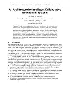
ABSTRACT This paper discusses the implementation of the Secure Hash Algorithm (SHA-1) required in the Digital Signature Algorithm (DSA) and many other applications. A single computing module with 80-rounds operation is ideal for a compact size hardware implementation. The round-word calculation module is also simple as a 16×32 bit register with few XOR gates. For the higher throughput those designs can be pipelined to any order, but at the cost of hardware size.
Category and Subject Descriptors B.7.1 [Integrated Circuit]: Types and Design Styles – Algorithms implemented in hardware
General Terms Algorithm, Design, Security
Keywords SHA-1, Digital Signature, Secure Hashing Algorithm, Data Security, IPSec., VLSI
1. INTRODUCTION In the era of information technology and electronics commerce, data transmission using electronic means becomes more and more important. The National Institute of Standard and Technology (NIST) has issued the Digital Signature Standard (DSS) as its Federal Information Processing Standards Publications, FIP PUB 186-2 [1]. This standard specifies algorithms appropriate for applications requiring a digital, rather than written, signature. An algorithm provides the capability to generate and verify signatures. A private key is used in the signature generation whereas a public key is used in the verification process. Unlike the private key, the public key is assumed to be known in public. As such, anyone can verify the signature but the signature generation can be performed only by the possessor of the user’s private key. Hash functions are common and important cryptographic primitives. Beside their uses in digital signature scheme, they are also basic building block of secrete key Message Authentication Codes (MAC), including American federal standard HMAC [2] which is used in security protocols such as SSL and IPSec [3,4]. Other applications of hash functions are Permission to make digital or hard copies of all or part of this work for personal or classroom use is granted without fee provided that copies are not made or distributed for profit or commercial advantage and that copies bear this notice and the full citation on the first page. To copy otherwise, or republish, to post on servers or to redistribute to lists, requires prior specific permission and/or a fee. Conference '04, May 26-28, 2004, Bangkok, Thailand. Copyright 2004 ACM x-xxxxx-xxx-x/xx/0004...$5.00.
ISBN: 974-537487-3
password storage and verification, computer virus detectionand etc. An n-bit cryptographic hash is an n-bit hash which is oneway and collision-resistant. Current popular hashes produce hash values of length n = 128 (MD4 and MD5) [5] and n = 160 (SHA-1), and therefore can provide no more than 64 or 80 bits of security, respectively, against collision attacks. The newly NIST approved Advanced Encryption Standard (AES) [6] has offered three cryptovariable sizes, 128, 192, and 256 bits of security. There is a need for companion hash algorithms which provide similar levels of enhanced security. The SHA 256, 384 and 512 has been proposed for such need. They are much detailed in [7]. The comparative analysis of SHA-1 and SHA512 is given by Grembowski et al. [8]. A digital signature algorithm can also be used in proving to a third party that data was actually signed by the generator of the signature. It is intended for use in electronic mail, electronic data interchange, and other applications that require data integrity assurance and data origin authentication. The wireless protocols, such as HiperLAN/2 [9], and WAP [10], have specified security layers and the DSA have been applied for the authentication purposes. Many applications that include DSA are generally implemented with software approach. Those can be too slow for many modern communications. In the hardware approach, there are also number of SHA-1 encryption design cores available commercially in both ASIC [11] and FPGA [11,12]. The maximum achieved throughput is claimed to about 600 Mbit/s [12]. However in a particular case when the DSA or SHA is intended for small size application and/or dedicate firmware, unreasonable overhead cost can be further reduced by using only necessary and appropriate building blocks. With these regards and according to its implementability and variety of uses (i.e. both generation and verification of signature), we are focusing on SHA-1 in this paper. The rest of this section will be devoted to a brief revision of DSA. The Secure Hash Algorithm or SHA-1 will be given in details in section 2. The massage padding that required for 512 bits data block completion is given in section 3. In section 4 we will describe functions and variable constants. Architectures of a single module operation as well as its corresponding pipeline version are given in section 5. On the fly-round-word computation scheme is elaborated in section 6 before the conclusion. The signature generation is defined with the following equations:
r=
gk
p
(1) q
s = k −1 ( M ''+ xr )
q
(2)
8
3rd Asian International Mobile Computing Conference (AMOC 2004), May 26-28, 2004, Thailand where a) g = h
( p − 1)/q p
, 1 < h < p − 1 , and 0 < k < q for a
randomly selected L −1
k,
L
< p < 2 is a prime for 512 < L < 1024 and L = 64m for any integer m , ( p limited to 1024 in the
b) 2
latest changes), 159 < q < 2 160 , c) q is a prime; 2
d) x is a private key randomly generated, 0 < x < q ; y is a public key, y = g x
p
,
e) M" = SHA − 1( M ) , for the message M . the received versions of r , s and M '' respectively.
g u1 y u 2
p
(3) q
If v = r ' then the message is verified, otherwise the message may be modified or incorrectly signed. Here;
w = s −1
q
, u1 = Rw
q
and u2 = r ' w
q
, where
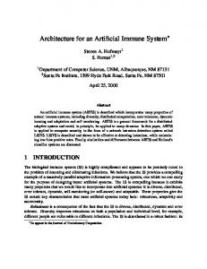
R = SHA − 1( M ') . Be noted that y , g , p and q are transparent to both the signatory and the receiver. The proof for v = r ' can be found in [13]. DSA Parameters (Private key incl.) Messages (M) SHA-1
The message digest together with other parameters are computed by the Digital Signature Algorithm (DSA) and the signature is obtained. The mentioned parameters are those required by the signature generation process denoted by (1) and (2) above. p and g are 512 bits data while others (such as private key x ) are 160 bits. As discussed above one may notice that SHA-1 is used in both the signature generation and verification process. An efficient SHA-1 computation can have a major impact on the DSA performance.
2. SECURE HASH ALGORITHM (SHA-1)
The verification process operates on r ', s ' and M ' which are
v=
infeasible to find a message which corresponds to a given message digest, or to find two different messages which produce the same message digest. Any change to a message in transit will, with very high probability, result in a different message digest, and the signature will fail to verify. SHA-1 is a technical revision of SHA (FIP 180).
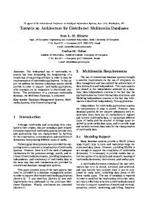
Illustrated in Fig. 2, SHA-1 requires the operation of 80 rounds which can be grouped into 4 groups, 20 rounds each. Each round operates on five 32 bits hashing words ( H 0 to H 4 which have A to E as their temporary versions. Functions and constants are basic operation of each round. Those constants are round constants ( Kt ) and message word constants ( Wt ). In summary, SHA-1 is written as: a) First block initialization:
A = H 0 = 67452301, B = H 1 = EFCDAB89 C = H 2 = 98BACDFE, D = H 3 = 10325476 E = H 4 = C 3D2 E1F 0 b) Initialize: A = H 0 , B = H 1 , C = H 2 , D = H 3 and E = H4 c) Perform 80 rounds; for t = 0; t < 80; t + + ;
DSA
T = Wt + Kt + S 5 ( A) + E + f ( B, C , D) Signature Generation Mess. (M) Signature Verification
DS
Signed Messages SHA-1
Et + 1 = Dt Dt + 1 = Ct Ct + 1 = S 30 ( Bt ) Bt + 1 = At At + 1 = T
DSA Parameters (Public key incl.)
DSA
Decision O/P (Y/N)
Figure 1: Digital Signature Generation and Verification Process Although SHA-1 specifies the output size of either 256 or 384 or 512 bits (as SHA-1/256, SHA-1/384 and SHA-1/512 respectively), we are aiming on the most complicate one. SHA1/512 has the complexity of exhaustive key search of 2 256 . This figure is similar to that holds by the AES with 256 bit key length. The input messages are thus divided into blocks of 512 bits. Message padding is applied to the last block to complete the 512 bit block size. The SHA-1 operates on those 512 bits data and condense them into a 160 bit data that so called digest. The SHA-1 is called secure because it is computationally
ISBN: 974-537487-3
(4)
for t < 16 ; L W t = Wt and for t ≥ 16
Wt = S 1 ( Wt − 16 ⊕ Wt − 14 ⊕ Wt −8 ⊕ Wt − 3 ) .
(5)
Kt are variable constants given below. K1t = 5 A827999 , for 0 ≤ t ≤ 19 , K 2 t = 6ED9EBA1 , for 20 ≤ t ≤ 39 , K 3t = 8F 1BBCDC , for 40 ≤ t ≤ 59 , K 4t = CA62C 1D6 , for 60 ≤ t ≤ 79 . And f ( B, C , D) will be detailed in section 4. d) Final Adds:
H 0 = H 0 + A , H 1 = H 1 + B, H 2 = H 2 + C
9
3rd Asian International Mobile Computing Conference (AMOC 2004), May 26-28, 2004, Thailand H 3 = H 3 + D , and H 4 = H 4 + E .
+
For (4) – (6) above, reduction (i.e. mod
(6)
denotes addition with modulation j = 31
x32 , for any 32 bits word z = ∑ a j x j , j =0
a j ∈ {0,1} )
and S
n
denotes n places circular left shift.
Wt can be computed for word-divided padded massage. For the next data block, the process loops to step b). To compute the round word ( Wt ), data is segmented into the block of 512 bits. The last block is padded with “1” and several “0” and the data length to complete 512 bit block size. Detail of message padding is given in section 3 below. After the last block has been processed, message digest ( M" , 160 bits) is obtained.
M " = SHA − 1( M ) = { H 0 , H 1 , H 2 , H 3 , H 4 }
61626364 00000000 00000000 00000000
65800000 00000000 00000000 00000000
00000000 00000000 00000000 00000000
00000000 00000000 00000000 00000028.
4. FUNCTIONS AND CONSTANTS Secure Hash Algorithm defines function f ( B, C , D) for each round as follows:
f ( B, C , D) = B • C ^ B • D , for 0 ≤ t ≤ 19 , f ( B, C , D) = B ⊕ C ⊕ D) , for 20 ≤ t ≤ 39 , f ( B, C , D) = B • C ^ B • D^ C • D , for 40 ≤ t ≤ 59 , f ( B, C , D) = B ⊕ C ⊕ D , for 60 ≤ t ≤ 79 .
(7)
here • denotes logical AND, ^ denotes logical OR, and ⊕ denotes logical XOR. Variable constants used in every round are Kt and Wt given above in section 3.
Message (M) Round Initialize A, B, C, D and E
Message Padding
5. ARCHITECTURES FOR SHA-1
K1t Round 0 - 19 K2t Round 20 - 39 K3t Round 40 - 59 K4t Round 60 - 79
Final Round Addition
Next Block Initialization
Round Word Computation (Wt)
The rest two words are preserved for the original message length. In this case 40 = “00000000 00000028”. As a result, the passed massage is
Last Block
Two main functions of SHA-1 are round function and round word computation. The implementation of SHA-1 in both iterative mode and pipeline modes are given in this section while the corresponding round-word computation is detailed in section 6. An architecture of the SHA-1 round operation detailed in section 2 is shown in Fig. 3 below. E + Wt + Kt is computed 5 in parallel with f ( B, C , D) and S ( A) . The circular n-place shift operation is fast and easy with data line hard-wiring. We
applied the same technique to S 30 ( B) operation. This shifting operation operates in parallel with the second summation (BCLA_2).
MPX A A’
2 B
Figure 2: Secure Hash Algorithm (SHA-1)
C
B’ C’
f(B,C,D) BC LA_3
D
BC LA_4
3. MESSAGE PADDING The massage padding is applied to the last data block such that SHA-1 can process the data of n×512 bits. The last two words of padded message are reserved of the original message length (in bits). In summary, massage padding operates as follows: 1) “1” is padded next to the message data bit (right side), 2) m consecutive “0” are padded to complete the length of 448 bits, 3) last 64 bits are for the original length. For example, message of the last block is given as: 01100001 01100010 01100011 01100100 01100101. The message length is 40. After ‘1” is appended, 407 ‘0’ are required to complete 448 bits. In Hex, this can be written as: 61626364 00000000 00000000 00000000
65800000 00000000 00000000 00000000 00000000 00000000 00000000 00000000 00000000 00000000.
ISBN: 974-537487-3
D’ E’
E Wt BC LA_2
Kt
32 bits
RSHA-1
BC LA_1
Figure 3: Round Operation of the SHA-1 (RSHA-1) For the round function f ( B, C , D) given in section 4 above, logic block comprises of AND gates, XOR gate, Inverters and round selection multiplexers. Each data path is 32 bit wide. The implementation is given in Fig. 4 below. In the implementation of a modulo reduction adder required in the implementation of round function given in Fig. 3, we have investigated such SHA-1 with three type of 32 bit parallel adders. These are Carry Propagate Adder (CPA), Carry Look Ahead Adder (CLA), and Block Carry Look Ahead Adder (BCLA) with different sub-block sizes of 4, 8 and 16 bits CLA. Performances are shown in Table 1 below.
10
3rd Asian International Mobile Computing Conference (AMOC 2004), May 26-28, 2004, Thailand
= OR = AND = XOR B f(B,C,D)
C
D
Rd_sel R1
Although the throughput can be boosted by internal pipelining of the RSHA-1 module, what one has to pay for is the increasing of gate utilization. Upon our experiment, per one round computation cell, CLB slice increased by the factor of 1.5. The implementation of round-word calculation is fairly easy when Q ≤ 5 . For the new class of FPGA, the LUT can be employed for better results. However for the higher number of pipeline stage (i.e. Q > 5 ), the design will cumbersome and the gate count increases dramatically.
32 bits Message
160
Figure 4: Round Function f(B,C,D)
Stack Message Padding
BCLA
CLA
Wt
8b
4b
2092
1161
952
580
472
CLB Slices
1046
581
476
358
236
Max. Path Delays (ns)
26.9
30.5
24.6
23.8 46.6
Wt
32
20
32
20
RSHA-1
32 160
20
20
RSHA-1
RSHA-1
32
K1t
Stack
Wt
160
160
32
Function Generators
512
Wt 32
160 Bits Initialized Vectors (A,B,C,D and E)
CPA
16 b
512
160
Table 1: Performance Evaluation of SHA-1with Different Type of Adders (HDL: Xilinx 2V1000FF896)
512
512
160
160
RSHA-1
32
K2t
32
K3t
K4t MPX
160
for next data block
Output
Figure 6: Pipeline Implementation of SHA-1 (Q=4) Considering the above table one can notice that the Block Look Ahead Adder with 4 bit sub-block offers very good performance (in term of resource utilization and delay times) compared to others. We thus will use this type of adder in the followed implementations. For each 512 bit data block operation, the scheme given in Fig. 3 above is used iteratively for 80 rounds. For minimize hardware requirement only a single block can be designed. As shown in Fig. 5, the thick data paths are 160-bit wide. Kt are stored in four 32-bit registers, each is for 20 rounds.
First Round Vector Round Initialize Vectors (AÆE)
32
32 Output (M”)
160
Round Word Comp.
Kt
MPX
Message Padding
MPX 160
Message (M)
Wt
80 RSHA-1
MPX
160 160
6. ON THE FLY ROUND-WORD COMPUTATION Based on equation (5) given in section 2, for t ≥ 16 the round-word W t can be computed from a single left-shifted version of the XOR sum of the prior 4 words; i.e. W t − 16 , W t −14 , W t − 8 , and W t − 3 . We thus need 16 of 8 bits location to store 16 words and use 4 of them. The computed round-word is looped back to store in the previously used location. The same process repeats for other 3 loop sets. The architecture that supports the above discussed data flow can be designed strait forwardly. As shown in Fig. 7, a 16×32 bit register, 2 multiplexers and 3 XORs are required. MPX_1 passes 16 first round directly to the SHA-1 computing blocks shown in Fig. 5. Data are shifted to the right every clock cycle. Data are cycled to complete 80 round when the feedback path is enable via MPX_2 (the 512 bits message is completed in the first 16 clock cycles). With this arrangement W t is obtained in very clock cycle.
160-bit (Bidirectional)
Padded Message
Figure 5: An Iterative Use of a Single RSHA-1 Module To perform the pipeline computation, the single iterative block (RSHA-1) shown in Fig. 3 above can be cascaded. The throughput can be made higher upon the number of pipeline stage Q . However, the hardware size is increased with proportion to Q . The throughput (TP) can be easily computed from
160 bits / clock cycle TP = 80 /Q An illustrated example of the pipeline SHA-1 computation is shown in Fig. 6. Q is set to 4, such that the arrangement is similar to that given in Fig. 2. The throughput of 160 bits/20 clock cycles with the latency of 80 clock cycles could be obtained. With this calculation, the 80 stage fully-pipelined scheme can offer the throughput of 160 bits per clock cycle.
ISBN: 974-537487-3
32
Rnd_cn t 0
Wt
MPX_2
32
16 x 32 bit Register 1
2
3
4
5
6
7
8
9
A
B
C
D
E
F
MPX_1 32 = XOR
Block_M