An Architecture for Hierarchical Collision Detection ∗ Günter Knittel
Gabriel Zachmann
WSI/GRIS University of Tübingen email:
[email protected]
Computer Graphics, Informatik II University of Bonn email:
[email protected] Abstract
We present novel algorithms for efficient hierarchical collision detection and propose a hardware architecture for a single-chip accelerator. We use a hierarchy of bounding volumes defined by k-DOPs for maximum performance. A new hierarchy traversal algorithm and an optimized triangle-triangle intersection test reduce bandwidth and computation costs. The resulting hardware architecture can process two object hierarchies and identify intersecting triangles autonomously at high speed. Realtime collision detection of complex objects at rates required by force-feedback and physically-based simulations can be achieved. Keywords: graphics hardware, computer animation, virtual reality, hierarchical algorithms, triangle intersection.
1 Introduction Collision detection is an elementary task in areas like animation systems, virtual reality, games, physically-based simulation, automatic path finding, virtual assembly simulation, and medical training and planning systems. In many of these systems, collision avoidance or collision handling is the ultimate goal. Since algorithms for computing the exact time of collision are still too slow or too restrictive, most approaches are “reactive” in that they first try to place objects at a new position, then check for collision, and then try other positions, based on physical laws or constraints [21, 14]. This poses very high demands on collision detection performance, because they must do many collision checks per simulation cycle. Another very demanding application is rendering force-feedback, where collisions of an (invisible) surface contact object must be checked at about 1000Hz in order to achieve stable force computations. It has been reported by many researchers that collision detection is still the major time-consuming step in many simulation or visualization applications [14]. Since collision detection is such a fundamental task, it would be highly desirable to have hardware acceleration available just like 3D graphics accelerators. Using specialized hardware, general-purpose processors can be freed from com∗
This is a slightly extended version of the WSCG ’03 paper
puting collisions. This will enable even low-end single-processor PCs and game consoles to do realtime collision detection in very complex scenarios at an affordable price. In this paper, we propose an architecture which implements hierarchical collision detection for rigid objects in hardware. We have concentrated on hierarchical algorithms, because they have offered the best performance for so-called “polygon soups”. Such a collision detection hardware will comprise the last stage of a collision detection pipeline [20]. This is where the bulk of the work is done in typical scenarios involving a modest number of objects with large polygon counts. We assume the hierarchies have already been computed. This is not a time-critical task, and can be done in software when the application loads objects at startup time. The next section describes related work, while Section 3 describes novel algorithms that are suitable for hardware implementation. Section 4 describes the hardware design in detail. Finally, Section 5 presents some benchmarks and considerations about the performance of the envisioned architecture.
2 Related Work Hierarchical collsion detection. Considerable work has been done on hierarchical collision detection in software [6, 17, 5, 4, 19]. Some of the bounding volumes (BVs) utilized are spheres, axis-aligned bounding boxes (AABB), oriented bounding boxes
(OBB), and discretely oriented polytopes (DOP). However, all traversal schemes proposed so far are inefficient in that they possibly visit the same nodes many times. Collision detection in graphics hardware. There is virtually no literature about the design of hardware architectures dedicated to collision detection. All research so far has tried to utilize existing graphics hardware. The approach taken by [16, 13, 2] is to render the pair of objects with an orthogonal projection and counting certain cases of overlapping intervals in the stencil buffer. This approach lends itself well to convex objects and a very special class of non-convex objects. The more general case of arbitrary concave objects cannot be solved efficiently with todays rendering hardware. Furthermore, the most general case of “polygon soups” (which comprises non-closed objects, in particular) cannot be handled by this approach at all. Another approach of utilizing the graphics hardware is to define a viewing volume (frustum or box) around one of the objects (the query object) and render the scene against that volume [10]. This is facilitated by OpenGL which can feed back the faces actually being rendered. This approach can be efficient for specific applications. However, it is not an accurate collision detection, unless the query object has the same shape as one of the two possible viewing volumes. All of the approaches using graphics hardware have the disadvantage that they either compete with the rendering module for the graphics pipe, or an additional graphics board must be spent for collision detection. The former slows down the overall frame rate considerably, while the latter would be a tremendous overkill, since most of the resources of the hardware would not be made use of. Furthermore, these approaches work in image space, which reduces precision significantly. Polygon intersection tests. A number of algorithms for ray-triangle and triangle-triangle intersection have been presented in the literature [1, 12, 7, 15, 3, 18, 11]. Most of them compute either the barycentric coordinates or a number of 4 × 4 determinants. We propose a very efficient algorithm for checking intersection of triangles that does not need any division. Our new algorithm not only uses less multiplications and additions than [11] and [1], but is also very well suited for a hardware implementation due to a very uniform control and data flow.
3 The Algorithm 3.1 DOP Trees The basic operation of any hierarchical collision detection algorithm is the overlap check of two nodes from different objects. In this section, we briefly recall the calculations necessary for collision detection using DOP trees. The derivation of the following formulas can be found in [19]. DOPs are bounding volumes that are a generalization of axis-aligned bounding boxes. They have been introduced into computer graphics by [8]. DOP trees are a hierarchical representation of objects [19, 9]. Each inner node stores a DOP and pointers to its children which it encloses; leaves store polygons (or other graphical primitives). A DOP is described by k numbers (hence k-DOP ), usually represented by a vector of k floats. Extensive benchmarks have shown k = 24 to be optimal. Given two objects OA and OB , and two DOPs d, e ∈ Rk from OA and OB ’s DOP trees, resp., the overlap test proceeds in two steps: first, DOP d from OA ’s hierarchy is transformed into d 0 in the coordinate frame of OB by d0 = C × d + c where
... .. C= .
c0,0
. . . ck−1,0
(1)
,
...
c0,1
...
c0,2
...
...
ck−1,1
...
ck−1,2
...
where in matrix C exactly three entries per row are non-zero. Second, d 0 is compared componentwise with DOP e according to ∃i ≤
k 2
: di0 < −e k +i ∨ ei < −d 0k +i 2
d and e do not overlap
2
⇔
(2)
where di0 < d 0k +i define a slab (analogously for all 2 DOPs). Matrix C and vector c depend only on the position of the two objects relative to each other. They are computed during the set-up by the software API of the collision detection hardware. Since the k × k-matrix C in Equation 1 has exactly 3 coefficients per row that are not 0, we can compute d 0 more efficiently by dji,0 di0 = Ci dji,1 + ci (3) dji,2
A1
A
B
D
B2
C
E
F
G
B3
D4 D5 E4 E5 D6 D7 E6 E7
1
F6 F7 G6 G7
3
2
C3
C2
4
5
6
7
F4 F5 G4 G5
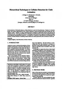
Figure 1: The simultaneous traversal of two BV hierarchies is, conceptually, equivalent to the traversal of a BV pairs hierarchy. Here, the right DOP tree is “tumbled” with respect to the DOP orientations of the left tree’s reference frame.
where correspondence j stores the place of those coefficients which are not zero. So, by introducing a k × 3 correspondence matrix j, we can reduce the size of the transformation matrix C to k × 3. Consequently, the number of multiplications is 3k.
3.2 Hierarchy Traversal
traverse(A,B) if A and B do not overlap then return end if if A and B are leaves then return intersection of primitives encl. by A and B else for all children A[i] and B[j] do traverse(A[i],B[j]) end for end if
The general, traditional scheme for hierarchical collision detection is a simultaneous, recursive traversal of two BV hierarchies. (see Algorithm 1). However, this procedure incurs several penalties: Algorithm 1: The traditional traversal scheme. A[i] 1. Nodes in both trees are usually visited sev- and B[j] are the child nodes of A and B, resp. For eral times; this is a general problem of all hi- sake of clarity, the “mixed” cases (one node is a leaf, erarchical collision detection algorithms (see the other is not) are omitted. Figure 1). 2. If the nodes have to be transformed (or other hierarchy and compare each node of that one with computations specific to individual nodes have a list of nodes from the other hierarchy. Let us call to be performed), then this will be done sevnodes that need to be transformed tumbled nodes, eral times for the same node. the other ones aligned nodes (see Figure 1). AsThe second penalty is a consequence of the first sume that we are visiting a tumbled node A, and one; it could be alleviated by storing the result that a list L contains all aligned nodes with which of the node transformation back into the node. A needs to be checked for overlap. So we check Unfortunately, this has other disadvantages: first, all pairs (A, Li ); whenever such a pair overlaps, the BV hierarchy occupies more memory (in the we append the two children Li , j ∈ [1, 2], to a new j case of DOP trees, this would increase the memory list L 0 . After L has been completely processed, L 0 usage by a factor 2); second, more importantly, contains all aligned nodes that need to be checked the algorithm would no longer be thread-safe, so with A1 and A2 , the two children of A. It is obvithat multiple pairs of objects could no longer be ous that with this traversal we visit each tumbled checked in parallel. node only once, and thus we transform the DOP In contrast, our novel traversal scheme reduces stored with it exactly once. the number of nodes visited, transfer volume from This scheme works for all kinds of hierarchical memory, and number of node transformations dra- collision detection, not just DOP trees. Dependmatically. Our traversal scheme only needs an ad- ing on how much work per node-node overlap test ditional small stack. can be factored out into one of the two nodes, the The idea is to avoid simultaneous traversal of benefit of our new method can be dramatic. two BV hierarchies. Instead, we traverse only one
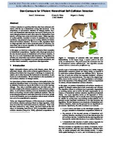
For example, considering Figure 1, a possible sequence of pairs of nodes could be: A1 B2 D4 E4 D5 E5 C2 F4 G4 F5 G5 B3 C3. This means, that with the classical traversal the sequence of node transformations is: 1 2 4 4 5 5 2 4 4 5 5. In contrast, with our new traversal scheme, this sequence of visited node pairs is: A1 B2 C2 D4 E4 F4 G4 D5 E5 F5 G5 B3 C3, and the sequence of node transformations is: 1 2 4 5 3. A hardware implementations allows us to improve the algorithm further by performing DOP overlap tests in parallel. We can exploit the fact that if two nodes A, B overlap, then we always need to check all children pairs (Ai , Bj ), Consequently, instead of storing pointers to all children in the list L 0 , we store only one pointer for each pair of siblings. By the nature of the binary tree, performing two overlap tests in parallel yields the greatest cost/performance benefit. To this end, we load a sibling pair of tumbled DOPs (A, B), transform them sequentially, and compare the two in parallel with each DOP from L. This results in two new lists, one for child pair (A1 , A2 ) and one for (B1 , B2 ). In the sequential version described in the previous paragraph, we produced these two lists at very different times during the traversal, and we processed each of them twice; now, we produce those two lists simultaneously, and then we process each of them only once.1 The benefit of this is that the time needed for overlap tests and the number of times an axis-aligned DOP needs to be transferred from memory is cut by a factor of two. The pseudo-code in Algorithm 2 summarizes this new algorithm scheme. Note that, for clarity, we have omitted the “mixed” cases. Note also that the last call of traverse is actually a call of an overloaded version, which has only slight differences from the algorithm shown here. In a hardware implementation, we have to maintain the stack and the lists ourselves. This can be done by a stack of lists (see Figure 2). On the same stack, we keep pointers to pairs of tumbled nodes. Going down from node pair (A,B) to (A1 , A2 ), we push the pointer to (A, B) onto the stack. Later, when the recursion returns to this node pair, we need to decide whether to go down into node pair (B1 , B2 ) or to make a step upwards. This information can be kept in an additional bit on the stack: when the pointer is pushed onto the stack, the corresponding bit is reset; when we return to 1
This scheme can be generalized straight-forward to process 2m tumbled nodes simultaneously.
traverse(A,B,L) transform A transform B init L with pairs of first level beneath roots for all N ∈ L do if X and N do overlap then if X and N are leaves then check primitives enclosed by X and N else LX0 + = N1 , N2 end if end if end for if A is an inner node then 0 traverse(A1 , A2 ,LA ) else 0 traverse(A,LA ) end if if B is an inner node then traverse(B1 , B2 ,LB0 ) else traverse(B,LB0 ) end if
Algorithm 2: The new algorithm scheme for hierarchical collision detection that transforms each tumbled DOP only once, and that reduces the number of multiple visits of nodes by a factor 2. Operations involving node “X” are executed in parallel on both nodes A and B.
this node, we go down into the other branch and flip the bit to 1. When we return the next time, the algorithm knows to make another step upwards.
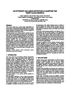
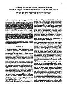
3.3 Polygon Intersection Test In the case of collision, the traversal reaches pairs of leaves containing triangles, which have to be checked for intersection. Assume triangle A is given by vertices V 1 , V 2 , V 3 and triangle B is given by vertices W 1 , W 2 , W 3 , both in their object’s reference frame. Assume triangle A is part of object OA , and B is part of OB . The approach in our algorithm is to check (conceptually) each edge of A against B, and vice versa. First, A’s vertices are transformed into the reference frame of OB . Assume further a 3 × 3 transformation MB for triangle B such that MB · (W i − W 1 ) maps onto the unit triangle (0, 0, 0), (1, 0, 0), (0, 1, 0). Then, we transform A by (MB , W 1 ) (see Figure 3). For sake of simplicity, we will call the new vertices V i again. Consider each edge PQ := V i V i+1 . If both Pz and Qz ≥ 0 or ≤ 0, then we skip this edge. Now
z
A
P
Q
1
x
B 1
S
y
Figure 2: The improved traversal scheme can be implemented by a stack of lists. (In a hardware implementation, the stack on the right is merged into the left one.)
we compute (conceptually) the intersection S of the supporting line X = P+tr, r = Q−P, with the plane z = 0, which is defined by t = − Przz as S = P − r Przz (we know rz 6= 0). We know that 0 ≤ t ≤ 1. We also know that Sz = 0, so we need to compute only Sx = Px − rx Przz and similarly Sy , which are, basically, the barycentric coordinates of the intersection point. Finally, we just check whether or not Sx ≥ 0 ∧ Sy ≥ 0 ∧ Sx + Sy ≤ 1. If so, A and B do intersect; otherwise, we check the other edges, and, in case of no intersection, we check B against A. In order to save the division and the vector subtraction (for r), we reformulate the condition as follows (assuming rz > 0): Px Qz ≥ Qx Pz ∧ Py Qz ≥ Qy Pz ∧ Px Qz − Qx Pz + Py Qz − Qy Pz ≤ Qz − Pz (4) If rz < 0, then we must compare with ≤ 0, ≤ 0, and ≥ 0, respectively. The algorithm gains its special efficiency because we can precompute the matrices MA and MB (they can be obtained from a simple linear equation system), and because we do not need to compute the exact intersection point. In our case of collision detection using DOP trees, we can store these matrices in the leaves instead of the DOPs. We do not need to check pairs of leaf DOPs, because the immediate check of triangles is faster. Storing the triangle matrix MB and 3 vertices needs 3 × 4 + 3 × 3 = 21 floats, which fit well into the nodes of a 24-DOP tree.
SDRAM Module 0
Figure 3: Using a special transformation, the intersection test can be done very efficiently.
SDRAM Module 1
SDRAM Module 2
SDRAM Module 3 64 Bits
256 Bits
SRAM CollisionChip (Stack) 36 Bits
PCI−Bus 32/64 Bits
Figure 4: Schematic diagram.
4 Hardware Design The target design is a PCI-board with one ASIC, a large on-board memory for the hierarchy, and a small SRAM as dedicated stack memory. Crucial for the performance is the bandwidth towards the local memory, and so a four-bank SDRAM configuration with a 256-bit bus was chosen (see Figure 4).
4.1 The CollisionChip Figure 5 shows all functional units of the CollisionChip. It consists of a number of large register files grouped around an arithmetic unit for floating-point dot-products (the DOTADD-unit), a Triangle Intersection Test Unit (IT-Unit), register banks connected to comparators, interfaces to the PCI-bus and to the local memories, the Stack Engine and control units as well as address generators. Although the processing of bounding volumes and triangles differ quite substantially, a common architecture was found with only low redundancy.
Although the design is geared towards high performance and the chip looks large on paper, the actual chip space will be modest. All register bits together require roughly only 100k transistors. Also note that for comparisons, IEEE floating-point operands can be treated basically like integers, which simplifies all comparators significantly. Expensive units are the DOTADD-Unit and, to a lesser degree, the IT-Unit and the four-port DOP Register File. However, units like these can be found on today’s CPUs and graphics chips, so one can be confident that the CollisionChip can be built at low costs using current technology. The design was laid out for k = 24 and single-precision IEEE floatingpoint operands. The chip will have around 450 signal pins, mostly due to the 256-bit bus, and should fit into a 600pin package including all power pins. The DOTADD-Unit. The DOTADD-unit is similar to transform units as found in modern graphics accelerators. Its basic function is to perform di0 = dk × Ci,0 + dm × Ci,1 + dn × Ci,2 + ci on 32-bit floating-point numbers. The indices refer to the location in the register files. Due to the absence of data dependencies in the control flow, it can be pipelined for high clock frequency and throughput. Processing of Bounding Volumes. Prior to the processing of two hierarchies, the matrix C and the coefficients c must be loaded into the Matrix Register File. Also, the correspondence indices i, k, m and n must be stored in the Correspondence Register File. This happens via the PCI-bus under software control, and occupies 24 lines in both register files. The software also transmits the pointers (local memory addresses) of the two root nodes as starting point to the Master Controller. A DOP from the tumbled object is loaded from memory and sequentially stored in the DOP Register File under control of Address Generator 1. After some constant delay (again predetermined by software) a sufficiently large subset of DOPelements d are or will become available in time for continuous evaluation of Equation 1. At this point in time, Address Generator 2 is triggered and the operands are fed into the DOTADD-unit. Note that for maximum performance, processing of the lines in matrix C occurs out-of-order, depending on the earliest availability of the required d-elements. Also note that a specific d may be used
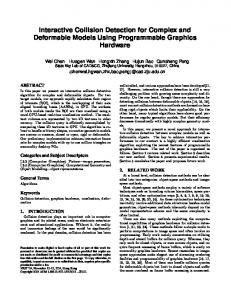
(Qz,Pz),(Px,Qz),(Qx,Pz),(Py,Qz),(Qy,Pz)
SIGN SIGN
32 32
30..0
30..0
FP SUB
FP MUL
1 XOR
Qz − Pz ADD/SUB
COMP
ACC
COMP
SIGN SKIP_EDGE IT−Control Bus to / from Master Controller
Figure 7: Intersection Test Unit for Triangles
for more than one line. The transformed DOPelements d 0 are then stored into the Results Register Bank under control of Address Generator 3, which basically delays an index i for the duration of the pipeline delay of the DOTADD-unit. The same processing is applied to the sibling of the tumbled node. The DOP-elements e of the aligned node are then loaded from memory in three transfers and stored in the registers labeled e0 . . . e23 under control of the Master Controller. The bank of comparators determines overlap in parallel and signals this condition to the Master Controller. The lists of child nodes to be checked for overlap are constructed according to this condition by the Stack Engine. Hierarchy Traversal. The novel traversal algorithm as described in Section 3.2 is implemented using a dedicated and fast external SRAM to store the lists and a suitably designed Stack Engine. Its basic task is to hand node pointers from the current list to the Master Controller and to receive child node pointers to construct new lists. Internally, it maintains a stack of list pointers and a register containing the actual level. Processing of Triangles. As described in Sect. 3.3, testing triangle A from object OA against triangle B from object OB requires transforming A into the coordinate system of OB using a rotation and a translation. These are constant for two objects, and can therefore be precomputed. The reverse test B against A may also be necessary, which requires the inverse transform. For maximum performance, all coefficients are kept on chip in the Matrix Register File in lines 24 through 29. After this first transformation, the triangle must then be transformed using the matrix stored in the leaf of the other triangle, whose coefficients are loaded
Module 0
Module 1
Module 2
Module 3 Data Bus D0...D255
Memory Address and Control Bus
SDRAM Interface Unit 8−to−1 Multiplexer
2−to−1 MUX
Address Generator 1
Address Generator 2 32
32
32
32
32
5 7
c0
i0
k0
m0
n0
C1,2
c1
i1
k1
m1
n1
d2
C2,0
C2,1
C2,2
c2
i2
k2
m2
n2
d3
C3,0
C3,1
C3,2
c3
i3
k3
m3
n3
C4,0
C4,1
C4,2
c4
i4
k4
m4
n4
C5,0
C5,1
C5,2
c5
i5
k5
m5
n5
C6,0
C6,1
C6,2
c6
i6
k6
m6
n6
C7,0
C7,1
C7,2
c7
i7
k7
m7
n7
i 62
k 62
m 62
n 62
i 63
k 63
m 63
n 63
i 64
k 64
m 64
n 64
i 65
k 65
m 65
n 65
d6 d7
... d 20
Matrix Register File
d5
Address Decoder Write Port
DOP Register File
d4
...
C29,0 C29,1 C29,2
c 29
C30,0 C30,1 C30,2
c 30
d 22
C31,0 C31,1 C31,2
c 31
d 23
C32,0 C32,1 C32,2
c 32
d 21
Correspondence Register File
C0,2
C1,1
Address Decoder Read Port 0
C0,1
C1,0
Address Decoder Read Port 1
C0,0
d1
Address Decoder Read Port 2
d0
...
6
5
5
5 D0 .. D20
32
32 each
Intersection Test Unit for Triangles
DOTADD−Unit
Address Generator 3
di0 = dk ∗ Ci0 + dm ∗ Ci1 + dn ∗ Ci2 + ci
IT Control Bus
7
5
Result Register Selector Results Register Bank Log.
OVERLAP / NO OVERLAP
Fnct.
d’
d’
d’
d’
d’
d’
d’
d’
d’
d’
d’
d’
d’
d’
d’
d’
d’
d’
d’
d’
d’
d’
d’
d’
>
>
>
>
>
>
>
>
>
>
>
>