cSER: Soft error resilience d AR-SMT: Active-stream/Redundant-stream Simultaneous Multi-threading. eSRTR: Simultaneously and Redundantly Threaded.
An Architecture for Runtime Evaluation of SoC Reliability ∗ Andreas Bernauer1 , Oliver Bringmann2 , Wolfgang Rosenstiel1,2 Abdelmajid Bouajila3 , Walter Stechele3 , Andreas Herkersdorf3 1 WSI,
Computer Engineering University of T¨ubingen D-72076 T¨ubingen bernauer@informatik. uni-tuebingen.de
2 FZI D-76131 Karlsruhe
{bringmann, rosenstiel}@fzi.de
3 Institute
for Integrated Systems University of Munich D-80333 M¨unchen
{A.Bouajila,Walter.Stechele, A.Herkersdorf}@tum.de
Abstract: This paper presents an architecture to evaluate the reliability of a systemon-chip (SoC) during its runtime that also accounts for the system’s redundancy. We propose to integrate an autonomic layer into the SoC to detect the chip’s current condition and instruct appropriate countermeasures. In the autonomic layer, error counters are used to count the number of errors within a fixed time interval. The counters’ values accumulate into a global register representing the system’s reliability. The accumulation takes into account the series and parallel composition of the system.
1
Introduction
The impending physical limits of CMOS technology lead to increasing process variability, thermal problems, degradation effects, and sensitivity for stochastic events. Recently, Intel [Bor05] presented a forecast about the development of critical device parameters. Random dopant fluctuations and sub-wavelength lithography will lead to large variances of device parameters, while dynamic effects like activity-based heat flux across the die and aging lead to changing circuit performance and leakage power. Furthermore, the devices will be increasingly sensitive for soft errors. These problems have been identified as the major challenge to be solved within the next decade. Intel claims that “we need to evolve from today’s deterministic design to probabilistic design for the future. The new design methods have to guarantee reliable systems composed of less reliable components.” Thus, we believe that future systems-on-chip (SoCs) have to adapt dynamically to changing internal and external requirements. The probabilistic design principle claimed in [Bor05] is a step in the right direction. However, the static fault and reliability models apply for average-case analysis and not for determining the actual condition of a particular chip, especially not during runtime. This paper presents an architecture that allows the chip to evaluate its current reliability during runtime which is used as a measure of the dynamically changing chip condition. The chip becomes able to react to de- or increasing reliabilities and to signal an approaching total failure, thus allowing pro-active actions. Current reliability evaluations either are carried out during runtime but don’t take the system’s redundancy into account ∗ This work is partially funded by Deutsche Forschungsgemeinschaft, Priority Program Organic Computing (SPP 1183) under the grants HE 4584/3-1 and RO 1030/14-1.
(e.g. [MFQX02]) or are carried out only during design time [SMM05]. Unlike other error detection mechanisms which focus mainly on identifying faulty parts, e.g. IBM’s Power5 processor-based servers, our approach focuses on the degeneration of the chip over time, as part replacement is not an option for SoCs. Our proposed architecture calculates the error probability of a particular SoC and accounts for the system’s redundancy. If the system’s structure changes due to failed components or deliberate reconfigurations, the evaluation is still applicable. The runtime reliability evaluation allows us to integrate autonomic system properties like self-organization, -optimization and -healing to tackle the following challenges: • • • •
Designing SoCs that can live with/work around faults to prevent system failure Dynamic balancing of the power, performance, reliability and security trade-off Adapting to changing environment Adapting to unpredictable faults (e.g. soft errors)
In order to spend only little overhead to integrate autonomic concepts on the die, our approach is based on the Autonomic SoC architecture presented in [LHR+ 05]. Our paper focuses on the dynamic evaluation of the chip reliability and not on autonomic concepts to manage critical reliability values. Section 2 explains the Autonomic SoC architecture in more detail. Section 3 shows how the reliability of the chip is calculated. Section 4 shows the proposed architecture in detail. Section 5 presents the augmentation of a SoC with an autonomic layer. The architecture is discussed in the concluding Section 6.
2
General concept
In [LHR+ 05] the authors present an architecture that augments a conventional system-on-chip with a layer of autonomic elements to increase the system’s dependability (Figure 1). The autonomic elements (AEs) in the autonomic layer monitor the function of the SoC layer, evaluate its current status and act on it according to a given goal, e.g. keeping a certain level of dependability. The actions of the AEs lead to a local error correction, a change of the system’s parameters, a reconfiguration of the system, or—as a fall-back if the countermeasures show no effect—a signal for the application indicating undesired circumstances like a component that is likely going to fail permanently. The acceptable component reliabilities depend on the particular apFigure 1. SoC layers plication. It can enforce the thresholds either by periodically monitoring the system’s reliability register (see below) or by using dedicated hardware that provides an appropriate interface for setting the threshold and signaling. This paper focuses on the evaluation of the monitors. One class of monitors are error detectors. References [BBH+ 06, INKM05] give a review of error detectors which may serve as AE monitors, summarized in Table 1. The main property of error detectors ap-
Table 1. Monitors that are usable in AEs and can be evaluated in hardwarea
Technique
Redundancyb
Architecture
Sequential logic Built-in SERc [MSZ+ 05] Reuse scan flip-flop from test circuit as redundant storage Shadow latch [Nic99] Shadow latch rereads protected latch’s input after a delay Combinatorial logic Duplication / self-checker Duplicate combinational logic or generate codes (residual codes, Hamming codes, parity) Razor [EKD+ 03] Shadow latch rereads protected latch’s input after a delay to allow for dynamic voltage scaling Architecture DIVA [WA01] Additional pipeline stage checks and skips over processor results by recomputing with a simpler checker processor modified DIVA Like DIVA, but without skipping over and eliminated struc[BBH+ 06] tural hazards AR-SMTd [Rot99], Execute program twice in a parallel thread SRTRe [VPC02] Dual use of superscalar Execute program twice by duplicating instructions when dispaths [RHF01] patching
H T H, I H
H, T H, T T H
a adapted from [INKM05, BBH+ 06] b H: Hardware, T: Time, I: Information c SER: Soft error resilience d AR-SMT: Active-stream/Redundant-stream Simultaneous Multi-threading e SRTR: Simultaneously and Redundantly Threaded processors with Recovery
IF
ID
Int1
Int1
Int2
Int2
LS FP EXE
MEM
WB
IF
ID
LS FP EXE
CPU1 Bus
Network I/O MEM
WB
Memory CPU2 FPGA
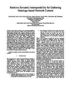
Figure 2. SoC with simplified depiction of the pipeline stages of the RISC processors. IF,ID: instruction fetch, decode; EXE: execution stage; Int1, Int2: integer unit 1,2; LS: load/store unit; FP: floating point unit; MEM: memory access; WB: write back stage
plicable for an AE is—besides actually detecting errors—that the detection can be carried out as a signal and thus can be logged and evaluated. As an example for a system with error detectors, consider Figure 2 which depicts a SoC with two CPUs, memory, network I/O, an FPGA and a bus connecting these components. Some more logic is not depicted. The EXE stage of the CPUs consists of two integer units, a floating point unit and a load/store unit. Clearly, if one of the two integer units in one CPU fail irrecoverably, this CPU can still operate (though with reduced performance) if its dispatcher is adjusted accordingly.
3
Reliability
The overall reliability of the SoC results from the dependence structure of the SoC’s components and the reliability of the particular components. The dependence structure can be
Total failure of Soc
Total failure of CPU i
OR
OR
AND
N
ID
IF
EXE stage fails
WB
MEM
B AND
M AND
C1
F
F
C1
OR
C2
FP
AND
C2 Int1
LS
Int2
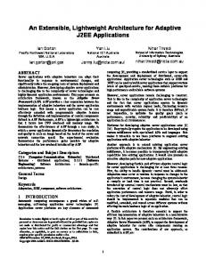
Figure 3. Fault tree of SoC from Figure 2. Left: Fault tree on component level. Right: Fault tree on subcomponent level in each CPU. N: Network; M: Memory; B: Bus; C1,C2: CPU1, CPU2; F: FPGA; IF, ID, Int1, Int2, WB, MEM: pipeline stages, see Figure 2. ‘OR’ collects components in series composition, ‘AND’ components in parallel composition
deduced from the fault tree of the system (e.g. in Figure 3) determined during design time. The reliability of a particular component is usually derived from analysis of the failure data of several copies of that component. This is not feasible on a SoC, as there are no several copies on a particular chip. Instead, we repeatedly test a single component several times. This will result in the same reliability value as testing several copies of the component if (a) the tests are independent (they don’t change the component) and (b) the single component represents an average component. Assumption (a) is violated in general, as we assume the components to degenerate over time. However, we may neglect the effect of degeneration during test time, as the time scale of degeneration is much larger than the time scale for testing. Assumption (b) is valid, as we are interested in the failure data of only this particular component, which of course is its own average. Our proposed architecture records the errors of a component during a fixed time period T = n∆t with ∆t being the length of a clock cycle. If the component C shows r errors during T , Pf (C) = nr is an estimate for the probability that the component shows an error in a clock cycle. Note that a component can show at most n errors in T as an error can be detected only every clock cycle. The reliability RS (t) of a system S is the probability that the system will work successfully at least until time t: RS (t) = P(t > t) where t is the random variable of the failure time. The two basic compositions describing the reliability structure of a system in terms of the reliability of its components are series and parallel composition. Equation (1) shows the error probability of a system in series composition S = AB, (2) shows the error probability of a system in parallel composition S = A + B in which A and B work redundantly, and (3) shows the error probability of a W system in parallel composition S = i=1...k Ai , in which at each ∆t only one of the Ai is
used with probability wAi . Pf (AB) = Pf (A) + Pf (B) − Pf (A, B)
(1)
≈ Pf (A) + Pf (B)
Pf
(1b)
Pf (A + B) = Pf (A)Pf (B) ! _ 1 Ai = ∑ wAi Pf (Ai ) k i=1...k i=1...k
(2) (3)
Pf (A, B) in (1) is the probability that A and B fail at the same time. As errors happen rarely, we may assume Pf (A, B) ≈ 0 (thus ignoring common mode failures). This avoids extra hardware that counts for Pf (A, B) and allows all error signals of a series composition to be OR-ed together. Note that in (2), A and B are assumed to fail independently, but may still fail at the same time. Recursive application of the equations (1)–(3) allows for compositions of any size and structure and gives an estimate for the error probability Pf (S) of a system in a clock cycle. Thus, the probability RS (T ) = P(t > T ) that the system will work successfully at least until T = n∆t is (with mn (x) = (1 − x)n ) Rs (T ) = P(t > T ) = (1 − Pf (S))n = mn (Pf (S)) As mn is a monotonic function, Pf (S) alone suffices as a measure of the system reliability: the higher Pf (S) the lower the overall system reliability.
4
Architecture
We add error counters to each monitor (or in the case of a series composition, a set of monitors), e.g. in Figure 4. After T elapses, the error counter values are read into a buffer, which now give the error probability of the monitored component in multiples of n1 during ∆t. While the error counters continue to count, a simple accumulator based reliability calculator calculates the system error probability. What follows is a detailed description of the architecture. Time measurement is done preferably by counting clock cycles, e.g. as done in the PPC440x5. The following constraints exist: • The number of cycles n must be a power of two, n = 2m , m ∈ {1, 2, . . . }: to stay comparable to other probabilities, the error probability of parallel components has to be divided by n (as Pf (A + B) = ab = ab/n n ), which is easily done by shifting if n2 m n=2 . • The time interval must be both large enough to allow for some errors to be counted and small enough to allow for timely reactions to increasing error counts. This depends on the actual component failure rates and the application. • The time interval must be chosen so that it can be most closely approximated by the clock counters in the different clock domains and still meet the other constraints. If there are d clock domains with frequencies f1 , f2 , . . . , fd , the timers will measure the same absolute time period if they count to ci = gcd( f ,fif ,..., f ) . 1 2
d
Register
Buffer
R
R
R
&
R
Ci
Temp
Op
Counter
Acc
n en
>1
C
reset
err
Figure 4. Error counter attached to error detectors (here: Razor elements, denoted by ‘R’)
Micro− code
ALU
Figure 5. Accumulator to calculate
Pf (S)
The error probabilities of the different clock domains have to be put on a common basis by multiplication and/or shifting before they are subsumed, e.g. Pf ,180 MHz (S1 ) = 3 · Pf ,60 MHz (S2 ) as 3 · ∆t180 MHz = ∆t60 MHz . In this case, the reliability calculator needs an extra temporary register (see below). The following sequence leads to the calculation of Pf (S) (see also Figure 4 and 5): 1. 2. 3. 4. 5. 6. 7.
T elapses. Set en of all error counters to low. No errors are counted from now on. Wait until any (ripple) error counter is stable. Read the counters into a (common) buffer. Reset the counters. Set en of all error counters to high. Errors are counted again from now on. Calculate Pf (S), a measure of the SoC reliability.
As errors are usually rare, missing to count the errors between en = low and en = high won’t introduce a large error. As T is large, the reliability calculation can easily finish in time. Note that the reliability calculation and error counting take place at the same time. The proposed reliability calculator is depicted in Figure 5. The microcode controls which error counter is loaded and which operation the ALU executes. From equations (1b)–(3) follows that the operations addition, multiplication and shifting suffice to calculate Pf (S) if k is a power of two. The microcode to calculate Pf (S) can be deduced from the annotated fault tree. The annotation identifies parallel components that do the same at the same time (as in (2)) or at different times (as in (3)). Using the associative law, the fault tree is minimized such that no two OR or AND operations follow each other. The longest path between any two operations is the amount of Temp registers the accumulator needs. Finally, using the commutativity law, the subtrees of every node are reordered by their depth in descending order, every OR is replaced with addition and every AND with multiplication or weighted averaging depending on the annotation. Assuming Acc = 0 at the beginning, traversing the tree in a depth-first way gives the microcode: every leaf (terminal) is loaded into the left operand and the last seen operation is performed. For averaging, a final averaging operation is added. A completed subtree is treated as a leave whose value is stored in a previously chosen and fixed Temp register. In the end, Acc holds Pf (S), a measure for the system’s reliability. We call Acc the reliability register. If a component C shows a permanent, unrecoverable error, the error counter of C or the series C is a part of is permanently set to n (i.e. Pf (C) = 1), respectively. The following measures avoid over- and underflow: saturating error counters, addition as well as
Counter C1 Int1
en
Int2 IF
ID
MEM
Counter C2
WB en
LS
EXE
FP
reset
n
err
OR
n Counter C3
en
Reliability Calculator
n
Figure 6. Pipeline stages (gray) with attached error counters (black) and reliability calculator (see Figure 5)
multiplication, and a special right shift operation whose result is at least one, if the shifted value is non-zero (overestimating the error probability by at most 1n for each component in series composition).
5
Implementation
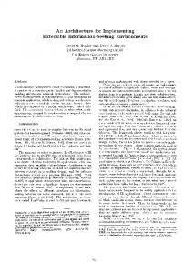
We show how our proposed architecture can be added to the SoC presented in Figure 2. It uses the following error detectors from Table 1: parity protection for memory, error correcting codes for the bus and Razor for the pipeline registers in the CPU. All error signals of a CPU except for the integer units are OR-ed together in a single error counter, as they are in a series composition. The error signals of the integer units are counted separately. The resulting architecture for the five pipeline stages of the CPU is presented in Figure 6. Only the CPUs need reliability calculators, as the other modules have only a single error counter. However, every module has its own error counter buffer. After the time intervals in each clock domains elapse, the sequence given in Section 4 is run. The calculation of Pf (CPU) is calculated as follows. The deepest subtree for a CPU is the parallel composition of its integer units (see Figure 3). Thus, after zeroing its registers, the reliability calculator in a CPU first reads the error counter C1 from the buffer and adds it to Acc. It then reads C2, adds it to Acc and shifts the result by m and 2. Finally, the calculator adds C3 to Acc, which now contains the probability that the CPU will fail in the next time interval. After calculating Pf (CPU), Pf (S) will be calculated. This particular system depends on at least one working CPU and a working bus, thus we can use the bus to transfer the error counter values to a working CPU. Alternatively, we could use a dedicated bus and reliability calculator. The error counter values are read into the buffer and calculation follows the expression derived from the fault tree given left in Figure 3. Finally, Pf (S) is stored in Acc. This register can either be sent to the actuators of the autonomic elements or read by the application.
6
Discussion
We showed how a SoC can be augmented by a layer of autonomic elements which monitor the functional part of the SoC and evaluate the SoC’s current status. The status evaluation is based on the calculation of the SoC’s error probability for a clock cycle and is performed purely in hardware. The necessary assumptions to allow for simple calculations are that
no two components in series composition fail at the same time, components in parallel composition fail independently and an appropriate time interval can be chosen to meet the constraints mentioned in Section 4. The assumption on the occurrence of errors ignores common mode failures, as current reliability evaluation tools do, too. Another problem results from compositions where r out of n components must work successfully for the system to work successfully. While this composition can be modeled with the proposed architecture (see Figure 3), the number of necessary calculations increase rapidly (namely like n!). It may be possible to approximate such compositions by an appropriate function.
References [BBH+ 06] Abdelmajid Bouajila, Andreas Bernauer, Andreas Herkersdorf, Wolfgang Rosenstiel, Oliver Bringmann, and Walter Stechele. Error Detection Techniques Applicable in an Architecture Framework and Design Methodology for Autonomic SoCs. In Proc. Biologically Inspired Cooperative Computing, 2006. [Bor05] Shekhar Borkar. Designing Reliable Systems From Unreliable Components: The Challenges of Transistor Variability and Degradation. IEEE Micro, 25(6):10–16, November/December 2005. [EKD+ 03] Dan Ernst, Nam Sung Kim, Shidhartha Das, Sanjay Pant, Toan Pham, Rajeev Rao, Conrad Ziesler, David Blaauw, Todd Austin, Trevor Mudge, and Kriszti´an Flautner. Razor: A Low-Power Pipeline Based on Circuit-Level Timing Speculation. In Proc. 36th Intl. Symp. Microarch., pages 7–18, December 2003. [INKM05] Ravishankar K. Iyer, Nithin M. Nakka, Zbigniew T. Kalbarczyk, and Subhasish Mitra. Recent Advances and New Avenues in Hardware-Level Reliability Support. IEEE Micro, 25(6):18–29, November/December 2005. [LHR+ 05] Gabriel Lipsa, Andreas Herkersdorf, Wolfgang Rosenstiel, Oliver Bringmann, and Walter Stechele. Towards a Framework and a Design Methodology for Autonomic SoC. In 2nd ICAC, June 13-16 2005. [MFQX02] Indrajit Manna, Lo Ken Foo, Guo Qiang, and Zeng Xu. Test Structures for On-Chip Real-Time Reliability Testing. U.S. Patent no. US 6724214 B2, April 2002. [MSZ+ 05] Subhasish Mitra, Norbert Seifert, Ming Zhang, Quan Shi, and Kee Sup Kim. Robust System Design with Built-In Soft-Error Resilience. IEEE Computer, 38(2):43–52, February 2005. [Nic99] Michael Nicolaidis. Time Redundancy Based Soft-Error Tolerance to Rescue Nanometer Technologies. In Proc. 17th IEEE VLSI Test Symposium, pages 86–94, 1999. [RHF01] Joydeep Ray, James C. Hoe, and Babak Falsafi. Dual Use of Superscalar Datapath for Transient-Fault Detection and Recovery. In Proc. 34th Ann. Int. Symp. Microarchitecture (Micro-34), pages 214–224. IEEE Press, 2001. [Rot99] Eric Rotenberg. AR-SMT: A Microarchitectural Approach to Fault Tolerance in Microprocessors. In Digest of Papers of the 29th Annual International Symposium on Fault-Tolerant Computing, June 1999. [SMM05] Tajana Simunic, Kresimir Mihic, and Giovanni De Micheli. Optimization of Reliability and Power Consumption in Systems on a Chip. Integrated Circuit and System Design, pages 237–246, 2005. [VPC02] T. N. Vijaykumar, Irith Pomeranz, and Karl Cheng. Transient-Fault Recovery Using Simultaneous Multithreading. In Proc. 29th Annual Int. Symp. on Computer Architecture, May 2002. [WA01] Chris Weaver and Todd Austin. A Fault Tolerant Approach to Microprocessor Design. In Proc. Intl. Conf. Dependable Systems and Networks, pages 411–420, July 2001.