7th International Conference on Automation Technology, (Automation 2003), May 8-11, Taiwan 2003
An Architecture to Extend the IEC61499 Model for Distributed Control Applications Kleanthis C. Thramboulidis Electrical & Computer Engineering Tel: +32 610997325 Fax: +32 610997316 E-mail:
[email protected]
ABSTRACT The function block (FB) concept has been adopted by the IEC61499 standard to define a model for the development of distributed control systems (DCSs). However, in our attempt to implement this model, we found that the FB approach is purely functional and does not exploit all the benefits of component-based development. In this paper we present our enhanced 4-layer architecture that proved to be very helpful for the identification of the key abstractions of the new generation FB-based Engineering Tools. The architecture of such a tool that should automate the development process of DCSs is also defined. We exploit the Unified Modeling Language during the analysis phase of DCSs, but we confect the use of the FB construct during the design and implementation phases. Even though the proposed approach is IEC-compliant, it introduces a number of extensions and modifications to the IEC-model to improve the development process. Keywords: Engineering tool, distributed control systems, Function Block, CASE tool, extending IEC61499. 1. INTRODUCTION Today’s rapidly changing market requirements impose the need of improving the agility of manufacturing systems. The always growing need for innovative products, forces manufacturing plants to improve their ability to quickly respond to market demands by designing competitive products and modifying existing ones. To address these requirements, the International Electro-technical Commission (IEC) defines, through the evolving standard IEC61499, the basic concepts and a methodology for the design of modular, re-usable, distributed Industrial Process, Measurement and Control Systems (IPMCSs) [1][2]. The standard defines the Function Block (FB) as the main building block and the way that FBs can be used to define robust, re-usable software components that constitute the distributed control system [3]. Part 2 of the standard defines a model of the engineering tasks to be performed during the design, implementation, operation and maintenance of distributed IPMCSs [4]. It specifies general requirements for software tools to support the associated engineering tasks. These tools are assumed to be parts of an integrated Engineering tool, which we call IPMCS CASE
Tool (ICT). Such an ICT must support the Engineer in the analysis, design, implementation, and configuration phases in a way compliant with the one defined by the IEC61499. An ICT will be considered as successful, according to the IEC61499, if it provides among others: • Software encapsulation and re-use, • System configuration support, • Migration of existing software and hardware to IEC 61499-compliant systems. In order for our ICT to address these requirements we have: 1. adopted state of the art Software Engineering practices to improve the development process of distributed IPMCS applications, 2. defined the CORFU framework, to fulfill the requirements imposed by the above process from the field bus, field device and the communication subsystem levels, 3. constructed an architecture for the wrapping of the various commercial field buses and field devices to the IEC level, and 4. enhanced our 4-layer IPMCS architecture. The above actions have resulted in a number of artifacts that constitute the background that was required for the development of our Engineering tool. The 4-Layer CORFU Architecture (4LCA) that was defined in [5] has been enhanced to allow the smooth integration of the above key issues and provide the abstractions required for the development of our prototype ICT, that is currently under development [15]. However, working out with IEC61499 for the development of our ICT, we have found that this standard does not specify a) the way that requirements are captured, and b) the low-level communication services that are required to distribute, configure, and control the operation of function block based control applications. We also found, that a number of modifications are required to improve the defined development process in terms of reliability, development time and degree of automation. The rest of this paper is structured as follows. In Section 2, the problem that our approach attempts to address is presented and the most recent proposals to this direction are discussed. Our process for the development of distributed control applications, and the CORFU framework that constitute the background of the work
7th International Conference on Automation Technology, (Automation 2003), May 8-11, Taiwan 2003 described in this paper, are briefly presented. In section 3, the extended 4-layer architecture is presented and key issues for the development of a new generation ICT are discussed. In section 4 our extensions and modifications to the IEC 61499 standard are presented. In section 5, we briefly refer to the process we followed for the development of our prototype ICT and finally, we conclude the paper. 2. BACKGROUND AND PROBLEM DESCRIPTION 2.1 Problem description During the last years, a lot of proprietary field buses have been installed in industry making the development and interconnection of control applications a burdensome task for control engineers. For each field bus, there is a proprietary tool for the development and configuration of control applications. These tools address a little or does not address at all, dimensions such as modularity, flexibility, extensibility, reusability, and interoperability. Furthermore, the need for the interconnection of the resulting control applications, on the different field bus segments, is only confronted after development and is implemented using proprietary gateways. These gateways do not usually guarantee the real-time requirements imposed by the nature of the control application and they do not support the unified development and configuration of the whole control system. A number of new proposals try to address these problems. First of all, the IEC61499 standard defines the basic concepts and a methodology to be used by system designers. However, this is only a specification that is under development and does not currently address all the issues involved in the development process. Another approach is the one carried out by the IDA group [6]. IDA wants to establish a vendor independent and open standard, adopting as its communication platform the TCP/IP protocol with real-time communication extensions. IDA’s application model depicts the structure and the basic elements of the control application and is based on the reference architecture defined in IEC61499. However, it restrains the IEC model in some aspects and extends or modifies it in some other. PROFINet is the Profibus proposal that adopts Ethernet, TCP/IP and DCOM to provide a component-based development process [7]. Although the PROFINet approach is not IEC-compliant it is planned to have an IEC-compliant mapping in the near future. 2.2 Our process for the development of IPMCSs The function block concept that is introduced by IEC standards, shares, as is very well pointed out in [8], many of the well defined, and already widely acknowledged benefits of the object concept introduced by the Object Technology. However, the whole approach is procedural like. New advances in Software Engineering should be
considered so as to exploit the maximum benefits introduced by them. The way that requirements are captured and transformed to function block design specifications is a very important issue that must be addressed, since the IEC standards do not cope with it. To address this issue, we have adopted best practices from component-based development and Object Technology, and utilized them to define the development process of distributed control applications. In order to exploit the Unified Modeling Language (UML) notation [9], we have defined our incremental development approach as a series of workflows, as described in detail in [10]. For the “capture requirements” that is the first workflow, we have adopted the use-case concept introduced by Ivar Jacobson [11]. During this workflow, end-users of the IPMCS, system analysts, and control engineers participate in order to properly define the system’s use cases, i.e. the system’s responses to external events that originate either from devices or humans. We have then defined, for the next workflow that is the “Capture Behavior” workflow, a process for the smooth transformation of the requirements expressed in the form of use cases to function block design specifications. During this workflow, control engineers create diagrams that capture the dynamic behavior of the system. Object-Interaction Diagrams (OIDs) are considered as the first realization of system’s use cases and are used to show the system’s internal objects and the way they collaborate to provide the required behavior [12]. During the next workflow, which is the “capture system static view”, engineers deal with the design of the static view of the system in terms of class diagrams. The control engineer has to go back and forth, between the above three phases, in order to produce consistent diagrams that constitute the analysis and design models of the system. As soon as these models of the system have been defined, we are ready to move into FB design specifications that are better understood by control engineers. A set of transformation rules has been defined to automatically transform the UML based system model into FB-based design specs [10]. 2.3 The CORFU framework To address the integrated development and configuration and to satisfy the real-time constraints of control applications, whose components must be distributed on a variety of field bus segments, we have defined a specific network topology. This topology utilizes ATM or Fast switched-Ethernet or even Gigabit Ethernet to provide the required quality of service in the communication level. On top of this topology, the CORFU framework was defined to facilitate the development, configuration, and operation of distributed IPMCSs [13]. The Industrial Process-Control Protocol (IPCP) has been defined to provide the set of services required for the interaction between the main components of the CORFU
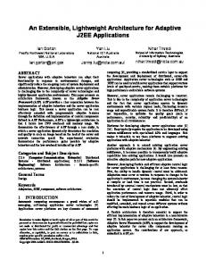
7th International Conference on Automation Technology, (Automation 2003), May 8-11, Taiwan 2003 framework. These components, which are shown in figure 1, are: the ICT, the Virtual Field Buses (VFBs), and the Human Machine Interface (HMI) modules. For the Interworking Unit (IU) to be able to interconnect the many different commercial field buses to the selected backbone, a modular and highly expandable architecture has been defined. This architecture satisfies the need for the real-time interconnection among field bus segments, as well as, the need for a similes development and configuration of distributed control applications over heterogeneous field bus segments. The VFB layer is used to abstract any commercial field bus, to the IEC61499 level so as the interoperability in field bus level may be achieved. A detailed description of the architecture of the IU is given in [5] and an updated version in [13].
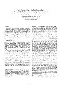
constructs play the role of proxies, in the developer’s workspace, of the actual real world objects. The second layer of abstraction that is called application-layer is used to represent the required constructs used in the analysis, design and implementation of IPMCS applications. Use case diagrams, object-interaction diagrams, scenario diagrams, class diagrams and FB diagrams, are the most important diagrams supported in this layer. Finally, the third layer of abstraction, the HMI-layer, captures all these abstractions that concern the development and operational phases of HMI modules.
Figure 2. The 4LCA and its projection into the development space.
Figure 1. Network topology for the CORFU Framework. 3. THE EXTENDED 4-LAYER ARCHITECTURE For the ICT to fulfill the requirements defined by the IEC61499, we considered the main spaces of the development process in combination with our 4LCA. The 4LCA is composed of the layers of abstraction that we discriminate in an IPMCS system. In figure 2, we present our 4LCA to cross vertically the development space. This perspective allows the smooth integration of our development process with the network topology and the network infrastructure, and proved to be very important in the identification of the key abstractions that the ICT must provide as building blocks of its various diagrams that are used during the modeling process of the control system. The bottom layer of the 4LCA, that is the industrial process layer, contains the controlled process. Boilers, valves, motors, etc., are the actual real-world plant components that constitute the artifacts of this layer. The next layer, which is the first layer of abstraction, is the system-layer. It is composed of abstractions used by the ICT to support the distribution and assignment process of the application’s components. It consists of appropriate software representations of real world objects like field devices, field buses, IUs, the backbone communication subsystem and their interconnections. These software
Motivated by the above perspective and to fulfill the tool’s requirements, we have defined for the ICT the system-layer editor and a set of application-layer editors. The system-layer editor should allow the engineer to construct in the design space, the system diagram and directly map it to the lower real-world layer. One of the means used to support such a direct mapping is the device specification. This specification, which must be compliant with a common device model, should accompany the device in a user readable representation such as the one accomplished using XML or XDDML [14][6]. Figure 3, presents the artifacts used in the process of appending a field device icon to the design space of the system layer. The engineer, working in the implementation space of the real world layer, connects the field device in the field bus. He/she will then insert, using the corresponding service of the ICT, the device’s representation into the design space of the system layer. Then using the XML field device specification and the appropriate ICT functionality, he/she will automatically create the machine-readable device model in the implementation space of the system layer. This is the last step for the realization of the device proxy’s assignment to the real field device. The device proxy is automatically created by the ICT in the implementation space of the system layer. After this assignment the engineer has full access to the real device. This access is required in the development, configuration but even in the operational phase of the IPMCS (i.e. for reconfiguration). An
7th International Conference on Automation Technology, (Automation 2003), May 8-11, Taiwan 2003 analogous process is followed for each type of component of the system level diagram.
primary concern. For example, for the assignment of a function block instance from the design space of the application layer, to the target field device in the real world layer, the control engineer has only to click on the function block instance and next on the icon of the corresponding device in the design space of the system layer, as is shown in figure 3. The ICT, using the API of the Configuration Management Entity (CME) of the VFB, which is described in the next section, downloads to the device, through the IPCP and the device’s proxy, the FB type definition in machine-readable format. The ICT then issues a “new instance” command to create in the target device, in the implementation space of the real world layer, the software module that implements the function block instance. 4. EXTENSIONS AND MODIFICATIONS PROPOSED
Figure 3. Artifacts of the ICT and CORFU framework in the development space. A set of editors supports the control engineer in the application layer. Each editor supports a specific diagram of those met in the application layer. Industrial Process Terminators (IPTs) and other actors, classes, FBs and data and event connections are the key abstractions and correspondingly the main building blocks of the application- layer diagrams. IPTs will be inserted into the design space of the application layer, to properly define the interaction of the control system with the plant. The IPT instances must directly be mapped to the actual devices that interface the IPMCS with the controlled processes of the industrial environment. The engineer analyses the physical plant and uses the appropriate software constructs to represent the key abstractions of the application domain. The ICT should provide all the functionality required for the physical distribution of the software building blocks to the system layer components and mainly to field devices and field buses. Partitioning, assignment and scheduling are among the engineer’s most important tasks that the ICT must support. Automatic code generation from the XML specification of the FB design diagrams and the corresponding FB type specifications is under development. An implementation scheme that allows run-time reconfiguration was adopted. The downloading of the produced executable code to the target system in the real world layer, and its corresponding configuration must be as user friendly as possible. Actions of the ICT that have no meaning in the design phase of the application, but refer to the configuration of the underlying communication subsystem must be properly hidden by encryption and encapsulation mechanisms. The higher layers of the 4LCA must be directly assigned to the real world layer and this assignment must be invisible to control Engineer. The required assignment mechanisms are introduced and implemented by the ICT in such a way that the encapsulation of all the details of such assignments are of
TO THE IEC61499 MODEL Working out for the development of our approach and the corresponding Engineering tool, we were guided to extend the IEC model to cover issues not supported and to modify it to improve the development process in terms of reliability, development time and degree of automation. 4.1 Extensions to the IEC-model We have extended the model in the following areas: E1) Capture requirements (functional and non-functional) We have already mentioned the way we capture functional requirements. Non-functional requirements and mainly FB execution times and relative and absolute deadlines, as well as real-time constraints on event and data connections are easily appended on the function block design diagrams using the stereotype extension mechanism of UML. However, it is not yet determined how these artifacts should be handled by the ICT during the distribution, downloading, and configuration phases. In any case, the ICT should notify the engineer, during the distribution phase, for the ability of the underlying device or communication subsystem to satisfy these constraints. E2) Transform requirements to function block design specifications We adopted OIDs to show the system’s internal objects and the way they collaborate to provide the required behavior. We next defined a set of transformation rules that fully automates the transformation of requirements captured in the form of use cases into function block design specifications. E3) Low-level communication services The IPCP, which was defined in the context of the CORFU framework, provides the services required to load, initiate, configure and re-configure FBs. These services are required both for the real-time interaction between VFBs, and for the non real-time interaction of the ICT and the
7th International Conference on Automation Technology, (Automation 2003), May 8-11, Taiwan 2003 HMI modules with VFBs. 4.2 Modifications to the IEC-model Our modifications are related with the use of the following special kinds of function blocks that are defined by the IEC standard: • Management function blocks • Service interface function blocks • Event function blocks M1) Management function blocks IEC61499 defines a special kind of function blocks, the Management function blocks and suggest the use of them to load, create and initiate function block execution. Management operations are outside of the problem domain and should not be defined by the control engineer. They should be provided by the underlying system i.e. the CORFU framework in our case. Even more, these operations are not modeled in the best way using the function block construct and we do not proceed this way. Instead of it, we have defined the Configuration Management Entity (CME) as part of the VFB as is shown in figure 4. We also defined the management services as part of the CME interface provided through the CM port. This interface is used by the ICT to perform the management operations that are related to function blocks. The proposed approach results in a more robust implementation and allows the CME functionality to be expanded to cover run-time reconfiguration requirements.
Figure 4. The CME is used for the configuration and reconfiguration of the FB-based control application. M2) Service interface function blocks IEC 61499 defines a special kind of function blocks, the Service Interface function blocks, to provide interfaces into the underlying resource and the communication subsystem. In this way the standard defines how data and event connections in the function block diagram should be implemented. We think that this is outside of the scope of the standard. In order to simplify the function block design diagrams we do not support service interface function
blocks. Instead of it, we defined a set of services in the IPCP to be used automatically by the CME, the Real Time Entity and the ICT to implement both the event and data connections. The following set of services has been implemented to allow the interaction between remote FBs: GET_DATA.req/ind/conf/resp GET_DATA_GROUP. req/ind/conf/resp POST_DATA.request/indication POST_EVENT.request/indication POST_EVENT_WITH.request/indication
Actions such as the implementation of data and event connections that have no meaning in the problem domain, but refer to the use and configuration of the underlying resource and communication subsystems must be properly hidden from the control engineer inside the ICT by encryption and encapsulation mechanisms. This approach also results in a more flexible reconfiguration process that is required during the operational phase. However, we still confect the SIFB construct to interface with the controlled process. We call them Process Interface FBs (PIFBs). M3) Event function blocks The standard defines a set of event function blocks that allow a wide range of different event scenarios to be modeled. Event function blocks such as event splitter, event merger, event rendezvous etc. are predefined and ready to be used by the designer. To simplify the function block design diagram and improve the performance of the resulting IPMCS system, we defined an event-API that should be provided by an IEC compliant device. For the design time, the function block design editor of the ICT provides a palette with event icons that are used by the designer to import in his model different event scenarios [15]. Later, during the downloading phase, the ICT automatically configures the device, through the configuration event-API, to provide the required behavior during the operational phase. This approach results in simplified function block diagrams and improves the performance of the control application. 5. TOWARDS A PROTOTYPE IMPLEMENTATION As far as the development of our prototype ICT, the development from scratch was considered as a waste of time. Such an approach could make the development of the ICT much more complicated and there is a danger to lose our focus from the actual problem. Existing CASE tools that support the UML notation may be used to elaborate to modern ICTs. The most of the modern commercially available CASE tools support the UML notation and a lot of this know how can be successfully utilized for the development of our ICT. We next came to the dilemma to adopt an open source CASE tool to form the basis for the development or to base the development of our ICT on a commercially available OO CASE tool. For the first case, we had to consider the Argo UML open source CASE tool that supports the UML notation and is entirely written in
7th International Conference on Automation Technology, (Automation 2003), May 8-11, Taiwan 2003 Java. However, we made the choice to build on a commercially available CASE tool although the use of an open source CASE Tool provides more flexibility, but at the same time longer development time. We selected Rational Rose, since it is one of the most popular CASE tools that support the whole life cycle from requirements through the final implementation. However, any other CASE tool that supports the OO approach may be used. At this stage, we considered two possible available solutions for the integration. Either to extent ROSE’s functionality through new menu commands, toolbar buttons and scripting, or to use external tools to support the extra functionality that is required by the ICT and is not provided by the general purpose CASE tool. In the latter case, the interaction of these additional tools with the general-purpose CASE tool may be obtained through the communication mechanisms provided by the tool. Rose, in our case, supports two mechanisms: the first one is based on a custom scripting language and the second is based on automation by running ROSE as a COM server. A description of the prototype Engineering tool that has been developed in the context of this work is given in [15]. 6. CONCLUSIONS In our attempt to develop an IEC61499-compliant Engineering tool we were guided to the definition of an infrastructure that greatly facilitated us in the analysis and the architectural design phases. This infrastructure satisfies the main goals set by the IEC for such a tool, i.e. software encapsulation and re-use, system configuration support and migration of existing software and hardware systems. For software encapsulation and re-use, we considered the use of state of the art Software Engineering practices and mainly the UML notation. The defined process enables the design and development of distributed IPMCSs using a) the widely accepted UML notation, and b) mature general-purpose CASE tools. To allow system configuration over heterogeneous field bus segments and migration of existing software and hardware to IEC 61499-compliant systems, we defined a modular and configurable architecture for the CORFU IU, and we have under development an Object-Oriented field device model. Our primary objective was to simplify the development of IPMCS applications by hiding complexities associated with field buses and field devices. We selected the IEC 61499 model to be the base of our work, but we found that this model does not address all of the issues involved in such an undertaking. We were guided to propose a number of modifications and extensions to ameliorate the development process. We focused on the abstractions required to identify reusable components and on the constructs that are necessary to support customization required by control applications. We are constructing the whole architecture of the ICT having in mind issues such as modularity, expandability,
robustness, and flexibility. This architecture promotes re-usability, obtains interoperability in the field bus level, and allows the similes development of control applications. We have found this architecture very helpful in the development process of our prototype ICT. 6. ACKNOWLEDGEMENT I gratefully thank Chris Tranoris, Polizois Parthimos, George Doukas, and Peter Manesis for their helpful discussions. 7. REFERENCES [1] IEC Technical Committee TC65/WG6, “IEC61499 Industrial-Process Measurement and Control – Specification”, IEC Draft 2000. [2] IEC SUB COMMITTEE No. 65C: “IEC1804 General Requirements”, IEC Draft 1999. [3] R. Lewis, Modeling control systems using IEC 61499, The Institution of Electrical Engineers 2001. [4] IEC Technical Committee TC65/WG6, “IEC61499 IPMCS, part2 –technical report – engineering task support”, IEC Draft 1999. [5] K. Thramboulidis, C. Tranoris, “An Architecture for the Development of Function Block Oriented Engineering Support Systems”, IEEE CIRA, Canada 2001. [6] IDA – Interface for Distributed Automation: Architecture Description and Specification, Revision 1.0, IDA group, November 2001. [7] PROFInet - Architecture Description and Specification (Draft),http://www.profibus.com/technology/documentation/texte/ 01295/, 2001 PROFIBUS International. [8] R.W. Lewis, “Modeling Distributed Control Systems Using IEC61499 Function Blocks”, Technical Articles, http://www.searcheng.co.uk/ selection/ control/tech.htm [9] J. Rumbaugh, I. Jacobson, G.Booch, “The UML Reference Manual”, Addison Wesley 1999. [10] C. Tranoris, K. Thramboulidis, “From Requirements to FB Diagrams: A new Approach for the Design of Industrial Control Applications”, 10th Mediterranean Conference on Control and Automation, MED 2002, Lisbon, Portugal, July 2002. [11] Jacobson, “Object-Oriented Software Engineering: A use-case driven approach”, Addison Wesley 1992. [12] K. Thrampoulidis, K. Agavanakis, “Introducing Object Interaction Diagrams: A technique for A&D”, Journal of Object-Oriented Programming (JOOP) June 1995. [13] K. Thramboulidis, “Development of Distributed Industrial Control Applications: The CORFU Framework”, 4th IEEE International Workshop on Factory Communication Systems, Sweden, August 2002. [14] Extensible Markup Language (XML) 1.0, W3C Recommendation, 6 October 2000. [15] C. Tranoris, K. Thramboulidis, “An IEC-compliant Engineering Tool for Distributed Control Applications”, 11th Mediterranean Conference on Control and Automation MED'03.