sations of contact and collisions. In this paper the problem of replicating external forces acting against the remote/virtual arm is addressed. The design of.
An Arm Exoskeleton System for Teleoperation and Virtual Environments Applications M. Bergamasco, B. Allotta, L. Bosio, L. Ferretti, G. Parrini, G.M. Prisco, F. Salsedo, G. Sartini Scuola Superiore S. Anna Via Carducci, 40, 56127 Pisa, Italy e-mail: bergamasco@sssupl .sssup.it of a force feedback system, it is necessary to introduce a first simplification to the problem: instead of considering a large continuos spectrum of application points, the locations on the human operator’s arm and hand where the force feedback system will operate should be reduced by considering an acceptable trade-off between the number of effectors to be controlled and the ultimate force sensation achieved during the execution of the specific task. A further consideration is related to the magnitude of the forces to be replicated. A first approach can be that of considering safety conditions for the functionality of the upper limb and hand fingers joints. However, aspects which are deeply tied with the functionality of the specific force feedback system should be taken into account [2]. In fact, the human operator controls the manipulative operation in the remote or virtual environment by having nothing in his/her hands in the real control space. Then the force feedback system has the main function of blocking the movements of the fingers or of the arm as soon as, in the remote/virtual environment, contact between the virtual hand/arm and virtual object is detected. Especially when grasping operations of ”heavy” virtual objects are considered, the magnitudes of the forces to be replicated to the fingers can result not suitable for the motors located in the proximity of the hand; in fact, for practical clearances factors, these actuators possess limited mechanical performances; it is then important to introduce a second simplification to the problem of force replication: we assume that contact grasping forces will be replicated by an exoskeleton system wrapping up the fingers, while large collision forces and large object weight will be replicated by an arm exoskeleton. In conclusion, manipulative procedures performed in virtual environments can generate different situations in which force feedback is required. The replication of weight associated with large objects (usually non- graspable) and also collisidn actions in correspondence of the arm is entrusted to a force feedback system acting directly on the arm; such a system can be named as an External Force Feedback system (EFF). When the dimensions of the virtual object dicrease, the forces associated with the virtual weight can be replicated by the EFF system except for those
Abstract The control of exploratory and manipulative procedures in Teleoperation and Virtual Environments requires the availability of adequate advanced interfaces capable not only of recording the movements of the human hands and arms, but also of replicating sensations of contact and collisions. In this paper the problem of replicating external forces acting against the remote/virtual a r m i s addressed. The design of an arm exoskeleton system developed an our laboratory is presented. The exoskeleton consists of a 7 actuated and sensorized DOF mechanical structure wrapping up completely the human arm and directly supported by the shoulders and the trunk of the human operator. Emphasis is given t o the implemented control procedures and t o the description of the transputer-based control architecture.
1 INTRODUCTION This paper deals with the problem of replicating to the human operator the forces generated during manipulative and exploratory procedures carried out in a remote or virtual environment. In general, in a real situation, collisions between the hand/arm complex can occur in different regions of the hand/arm surface. Contact forces generated during explorative operations performed by the human hand can be considered as mainly applied to the palmar surface of the fingers. The contact area on the palmar side of the hand greatly increases when manipulative operations involving power grip configurations are considered. The points of application of the forces to be replicated can then vary over large regions of the arm and of the hand. This is a critical issue for the realistic replication of contact conditions: the force feedback interface system should possess mechanical effectors capable of applying forces to the whole surface of the hand/arm complex. However, as outlined in [l], present actuator technologies do not allow the realization of such an ideal solution. Then, in order to address the practical design
1449 1050-4729/94 $03.00 0 1994 IEEE
precision grip operations in which the dimensions of the virtual object are extremely limited. The replication of contact actions during either precision and power grasps can be devoted to a force feedback system solely acting in correspondence of the hand (fingers and palm); such a system can be named as an Internal Force Feedback, or Hand Force Feedback system (HFF). The HFF system can also provide those external forces which act directly on the fingers during, for example, exploration procedures of objects (e.g. pressure actions on the virtual objects). The EFF and HFF systems do not cover the whole spectrum of forces which can be replicated on the hand/arm complex. In particular’ for those tasks of exploration or manipulation in which the control of a very fine contact condition is required, it is necessary to introduce another system, with specific mechanical performances, such as aTactile Feedback system (TF). In this paper the description of an External Force Feedback system is presented.
2 SYSTEMS FOR THE REPLICATION OF
EXTERNAL FORCES The study of force feedback systems lead to the design of different typologies of electromechanical systems usually conceived for teleoperation applications. However, their utilization also for virtual environment applications is fundamental when external force replication is required. From the realizations presented in the field of robotics and teleoperation, the following design solutions emerge: 1. electromechanical systems (for example, robotic manipulators or purposely designed structures) [5] possessing a kinematics with several DOF; these systems are grasped by the human operator at their end effector and follow the movement impressed by the human hand; when force controlled, they can exert the desired external forces in correspondence of the human operator’s hand. The external forces are generated by controlling the torques in each joint of the manipulator according to considerations deriving from the condition of static equilibrium. The human operator mobility in the control space is however limited by the constraint of grasping the end effector of the robot. Being the manipulator fixed to the ground, the effective workspace for the operator is given by the intersection of the manipulator workspace and the workspace of his/her arm. By means of this kind of electromechanical systems, the replication of the external force sensation is perfect since forces are really exerted by a system which is external with respect to the operator arm. However, the force replication can occur only a t the hand level and not in other parts of the arm; moreover the control of a complete manipulative operation cannot be performed since the finger’s mobility is not allowed; this last drawback could be overcome by designing purposely conceived attachments with the dorsal part of the operator’s hand and the manipulator end effector; 2. a second solution still comprehends an external system, fixed to the ground or to the wall, possessing
a workspace very close to that of the human operator; in this situation the same above considerations can be applied, although, in this case, the effective workspace is greatly improved [3]; 3. a different solution is obtained by considering arm exoskeleton systems. They consist in actuated and sensorized electromechanical structures, wrapping up the human arm, capable of recording joint movements and, when appropriately controlled, of exerting adequate forces on the arm. This solution introduces a near optimal resultant workspace (very close to that of the human arm) although, due to practical issues of mechanical construction, there are constraints for achieving the complete range of movement for all the human joints. Exoskeleton structures can be directly supported by the shoulders and trunk of the operator, where reaction forces and weight of the system is then distributed. The utilization of exoskeletons supported by the operator, and not attached to the ground, allows a complete mobility of the human operator inside his/her real control workspace. This is an extremely effective solution in those cases in which the human operator must interact not only with remote/virtual objects, but also, at the same time, with real objects in the control space (such as, for example, a control panel). A first solution for exoskeleton structures is that presenting only one attachment point with the dorsum of the human operator’s hand, and not with other points of the arm or forearm. The resultant force feedback sensation can be considered as perfect in the tract between the hand and the shoulder. On the shoulder and trunk some effects due to reaction torques generated during the application of forces at the distal end are present; 4. a variation with respect to the solution 3, refers to the number and locations of attachments between the exoskeleton structure and the operator’s arm. If attachemnts are considered also in correspondence of the medium part of the forearm and arm, it is possible to (locally) replicate desired forces also in these regions. In the following the description of the exoskeleton structure developed at Scuola Superiore S. Anna is given.
3 ARM EXOSKELETON At the ARTS Lab of the Scuola Superiore S. Anna, a complete force feedback system comprehensive of both EFF and HFF components for arm and hand has been developed. In the framework of this paper, the description of the arm exoskeleton implementing the functionality of external forces replication to the human operator’s arm is considered. The EFF system consists of a 7 DOF exoskeleton wrapping up the whole arm and supported, by means of a purposely conceived bust structure, by the shoulders and trunk of the human operator. The considered DOF imitate the joints of the human upper limb: there are 2 DOF at the level of the shoulder (flexionextension and abduction-adduction movements); 1 DOF in correspondence of the arm (rotation of the arm); 1 DOF at the elbow (flexion-extension); 1 DOF
1450
I4
k'!
-d3
b4
-7 d - 4
#7
a7
0
0
g
Table 1: Denavit-Hartenberg parameters of the arm exoskeleton structure been obtained without the use of idle pulleys, while the transmission systems for the elbow and forearm joints present complex cable routing. The correct arrangement of the cables and pulleys revealed as the most critical aspect of the whole design and testing phase. Torque sensors are now in course of integration in order to measure the differential tension of the cables actuating each joint. Joint rotation sensors have been integrated for each joint. The following values of the generated torques in each joint have been obtained: a) shoulder joint abduction-adduction and flexion-extension: 20 Nm; b) arm rotation and elbow flexion-extension: 10 Nm; c) forearm prono- supination: 2 Nm. The present appearance of the arm exoskeleton is depicted in Fig. 2: the total weight of the structure (in Al) with motors and transmission units is around 10 kilograms. Experimental tests have indicated that when the system is worn by the operator, and supported by his/her shoulders and trunk, the weight of the structure affects the manoeuvrability perfomances only when the system is not controlled. The human operator is connected to the exoskeleton structure at the level of the dorsal part of the hand, in correspondence of the metacarpus; in the present 5 DOF version, the 2 DOF of the wrist are not present and consequently the prono-supination joint a t the forearm is connected to the hand by means of a rigid link: in this configuration the human operator can control the movement of the exoskeleton by grasping a handle at the distal end of the last rigid link. No intermediate attachment is provided between other parts of the arm and/or forearm and the exoskeleton structure. We can then imagine the exoskeleton as a structure connected with the human body only in two locations: a) distally, the handle grasped by the hand, and b) proximally, the shoulders and trunk supporting the base link of the exoskeleton structure.
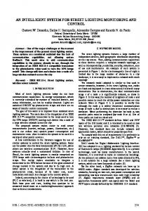
Figure 1: Kinematic-representation of the arm exoskeleton structure
in correspondence of the forearm (pronesupination movement); 2 DOF at the wrist level (flexion-extension and abduction-adduction). The arm exoskeleton described here refers to a structure with embedded only the first 5 DOF since, due to issues related to the functionality and wearability of the mechanical components, the 2 DOF at the level of the wrist have been designed and integrated with the HFF exoskeleton covering the hand. The two systems, EFF and HFF, present a mechanical interface at the level of the proximal region of the forearm where an attachement flange is present in correspondence of the output of the prono- supination joint. The scheme of the kinematic chain representing the complete 7 DOF system is reported in Fig. 1, while the associated DenavitHartenberg parameters are indicated in Table 1. Then, in principle, the arm exoskeleton structure possesses the capability to follow the significant movements of the human arm: limited constraints due to the mechanical structure do not allow to span the complete workspace of the arm. However, very good mobility is allowed around an initial reference position assumed as significant for manipulative operations (arm vertical, forearm horizontally flexed, intermediate position between pronation and supination). Each joint of the exoskeleton is actuated by means of DC servomotors located on the structure; this arrangement of the motors, although presenting a high degree of complexity in terms of design layout and packaging, allows the great advantage that the resulting system is completely portable and that no mechanical or actuation component is remotely located. The motion of each joint is obtained through a tension tendon-based transmission system: the 2 DOF of the shoulder and the arm rotation movements have
4 CONTROL OF THE EFF SYSTEM 4.1 Control Procedures As shortly outlined in the previous section, the exoskeleton structure can be considered connected to the human operator's arm a t the level of the hand and of the shoulders. In these two regions the exoskeleton structure can exert actions on the human body. These actions can be described by means of two systems of applied force vectors. The first is relative to forces between the exoskeleton base and the operator shoul-
1451
where J is the jacobian of the exoskeleton depending on the joint position vector q , F is the the wrench applied on the operator’s hand, and T is the vector of the joint torques. In dynamic situation and in presence of gravity, the joint torques that must be applied to give a desired wrench F d e s must contain additional terms devoted to compensate the exoskeleton inertia, Coriolis and centrifugal effects, friction, and gravity. A complete force mapping will thus be dependent on exoskeleton configuration, joint velocities and accelerations:
where M is the inertia matrix of the manipulator, C is the vector of Coriolis and centrifugal terms, D is the vector of friction terms, and G is the vector of gravity effects. Notice that the effect of compliance (for instance in the transmission system) is not included in (2). The model described by equation (2) can be used to build a controller that regulates the wrench F to a desired reference value. If good performance of the force replication system is required not only in quasistatic conditions the control must include the compensation of dynamic effects on the exoskeleton. If the requirements are not so strict in terms of bandwidth (say w o 5 3 rad/s), some of the terms of the full dynamic model can be neglected. In our case we decided to use only the gravity compensation term. This choice is justified by the following considerations:
Figure 2: Arm exoskeleton for replication of external forces ders; the second is relative to forces between the hand of the operator and the exoskeleton. Each of the two systems of applied vectors can be reduced to a resultant wrench. Under this assumption the exoskeleton system can be considered as an external robotic manipulator with its base link attached to the shoulders and trunk of the operator and exerting forces with its end effector (the handle) to the operator’s hand. The situation is similar to the case of an external manipulator exerting forces to the operator’s hand. However, in our case, the human operator perceives also a reaction wrench and weight of the “external” manipulator at the level of the shoulders. It was one of the goals of our experiments to verify that the incorrect force replication due to the wrench applied by the exoskeleton on the operators’ shoulders, did not affect the external force replication sensation. The assumption that actions on the shoulders and trunk of the operator can be considered as side effects in terms of force sensation on the operator has been confirmed by several tests concerning of pushing and explorative tasks. Under this assumption it is possible to replicate external forces by controlling the wrench applied by the exoskeleton on the operator’s hand. The variables that can be used to achieve such a control objective are the joint torques. In quasistatic conditions and with no gravity, the mapping between the applied wrench and the joint torques can be derived by means of the principle of virtual works and is given by the transpose jacobian of the manipulator :
0
0
quasistatic operation ensures that the effects of Coriolis and centrifugal terms are small; good backdriveability of joint actuators is ensured by the mechanical design and then friction is not high.
The feasibility of the control law will depend on the availability of external wrench and/or joint torques measurements. For the sake of simplicity in the following the dependency of J and G on joint positions will be omitted. If no force/torque sensors are present an open loop control law can be devised as follows: T
= G + JTFdes,
(3)
where G indicates an estimate of G. The open loop scheme cannot be used if non backdriveable drives are present. Furtherly, poor performance is expected due to friction and modeling errors in the estimation of G. If torque sensors are present the following control law can be devised: Tdes
=G
+ JTFdes,
(4)
where T d e s is a reference value for the joint torque vector. A servo term at the hand level based on the hand wrench error may be added to Fdes in order to improve the tracking of the reference value. A low level joint torque control loop is then used. Linear lead or lag controllers with feedforward have been proven to
1452
4.2 Description of the Control Architecture Criteria of high modularity for the control procedures have dictated the definition and design of the control architecture. Based on this criteria, the design of the control architecture has been addressed by considering transputer technology. By means of transputers it is possible to share out the computation load over an appropriate processor net and, at the same time, to respect the required timing constraints. Although, at present, the exoskeleton possesses 5 DOF, the actual processing system controls 7 DOF, since the 2 DOF of the wrist will be integrated with the HFF system. The control problem has been approached by dividing the processing system in different syncronous modules. These modules possess several rates, according to their own functionalities. It has been assumed that the servo control part of the system can run at around l k H z , while the dynamics and gravitational calculations are less critical in terms of the frequency of each cycle. Synchronization is obtained by generating a clock timing on the acquisition board and also by passing data among transputers through synchronous channels. Processes that run at lower cycle rates, such as the gravitational compensation module, utilize data sub-sampled by previous modules. The control architecture is completed with a part dealing with the communication to and from the exoskeleton. This communication part exploits as communication support the functionalities of the PC host. To obtain data transmission flexibility, asynchronous nonblocking transceivers have been introduced. The control is divided in several functional parts, as represented in Fig. 5. The system is conceived as a pipeline, from both logical and physiscal point of view. The system possesses a behaviour which is very similar to the virtual bus described in [7]. Two different implementation have been achieved. The first one, composed by 5 transputers, realizes the open loop force control procedure (3). In Fig. 6 the distribution of the computation for the control software dealing with the open loop procedure is described. The second implementation, dealing with the closed loop control procedure ( 5 ) , has been achieved by adding another transputer dedicated to the acquisition of the force/torque sensor information. Since the acquisition of the force/torque sensor, for constructive reasons, cannot be synchronous to the other force control information, processed in the remaining system, a manager process has been introduced t o guarantee the correct timing and utilization. The scheme of the closed loop configuration is depicted in Fig. 7.
Figure 3: Scheme of the open loop control procedure
F
Figure 4: Scheme of the closed loop control procedure be effective for the control joint torques [6], [4]. Joint torque sensing allows to overcome the problems of friction, although the measure of the wrench F is affected by many errors due to errors in the kinematic model of the exoskeleton, and rough or no modeling at all of exoskeleton dynamics. If a 6 components force/torque sensor is present, the loop can be closed at the hand level and the following control law can be used:
where K is a 6 x 6 diagonal matrix of constant gains. Closing the loop at hand level allows a better measurement of F , although the rejection of friction torques cannot be effective and is strongly dependent on the arm configuration q . Two different control procedures, based on equation (3) and (5) have been devised for the present version of the arm exoskeleton system. Control law (4) has not be implemented because joint torque sensors are not yet available on the prototype. The first procedure, schematically depicted in Fig. 3 refers to the open loop approach: desired external forces are modeled in the virtual environment and used to calculate the desired torques. A software block G(q) implementing gravity compensation has been introduced in order to take into consideration the effects of the exoskeleton weight in the calculation of the effective joint torques. A second procedure which exploits information of the interaction wrench F between the exoskeleton handle and the human hand has been implemented. This information is obtained by means of a force/torque sensor located at the base of the handle on the distal link of the exoskeleton structure. The scheme of this closed loop procedure is depicted in Fig. 4.
5 CONCLUSIONS The development of an arm exoskeleton capable of replicating external forces to the arm of the human operator has been described. The system now possesses 5 of the 7 DOF since the integration with a handlwrist exoskeleton is expected for the end of February 1994. Experimental tests have been already performed and have demonstrated the feasibility of the force replication approach. Although the system is connected to
1453
. .
. .
..,
1. .: larvl ’ i h !.
-3snr
. . ... :. .: I \: 4 i:
d
- 1 Kk
Figure 5: Scheme of the control architecture
the shoulders and trunk of the operator and not to the ground, as observed for the most part of present force feedback systems, the sensation of forces perceived by the human operator is acceptable and surely sufficient for the functional performance of primitive pushing and/or explorative tasks. The effects of the reaction forces and weight on the trunk of the operator are greatly overshadowed by the sensation of force that the operator perceives at the hand level during the control of the task. Future developments will consist in tuning the performances of the system as far as the increase of attachments with the arm will be considered; further mechanical improvements can be obtained in terms of workspace constraints and transmission system.
6 ACKNOWLEDGEMENTS This work has been supported by the Commission of the European Communities in the framework of the contract ESPRIT Project 5363 GLAD-IN-ART.
References [l] Bergamasco M . , De Micheli D.M., Parrini G . , Salsedo F., Scattareggia Marchese S., 1991, “Design Considerations for Glove-like Advanced Interfaces,” Proc. ’91 I C A R , International Conference on Advanced Robotics, Pisa, Italy.
n
[2] Bergamasco M . , 1992, “Design of Hand Force Feedback Systems for Glove-like Advanced Interfaces,” Proc. IEEE International Workshop on Robot and Human Communication, Hosei University, Tokyo, Japan.
Figure 6: Scheme of the software distribution for the open loop control procedure
[3] Johnsen E.G., Corliss W.R., 1967, “Teleoperators and Human Augmentation,” NASA SP-5047, Washington, DC: NASA Office of Technology and Utilization.
[4]D. Visher, 0. Khatib, 1989, “Design and Development of Torque-Controlled Joints,” Internal report, Robotics Laboratory, Computer Science Department, Stanford University, 1989.
[5] McAffee D., Fiorini P., 1991, “Hand Controller Design Requirements and Performances Issues in Telerobotics,” Proc. ’91 I C A R , International Conference on Advanced Robotics, Pisa, Italy.
[6] L. Pfeffer, 0. Khatib, 1989, “Joint Torque Sensory Feedback in the Control of a PUMA Manipulator,” IEEE Transactions on Robotics and Automation, pp. 418-425 Vol. 5, No. 4, August
1989. [7] Sharkey P.M., Daniel R.W., 1990, “Transputer control of a Puma 560 robot via the virtual bus,” IEEE Proceedings, Vo1.137, Pt.D. No. 4, July 1990.
Figure 7: Scheme of the software distribution for the closed loop control procedure
1454