Digital Multimeter. Portable DCCT. Pipes. GPIB. Figure 4. Architecture of the on-field test station. The main goal of the test is the commissioning [12] of (i) the new ...
16th IMEKO TC4 Symposium Exploring New Frontiers of Instrumentation and Methods for Electrical and Electronic Measurements Sept. 22-24, 2008, Florence, Italy
An Aspect Oriented-based Architectural Framework for Synchronization in Measurement Systems Pasquale Arpaia1, Mario Luca Bernardi1, Giuseppe Di Lucca1, Vitaliano Inglese2, Giovanni Spiezia2 1
Department of Engineering, University of Sannio, Piazza Roma, 82100 Benevento, Italy. Ph : +39 0824 305804-17, Fax: +39 0824 305840, E-mail: {arpaia-dilucca-mlbernar}@unisannio.it 2 Department of Electrical Engineering, University of Naples, Federico II, Via Claudio, Napoli, Italy
A bst ra ct - An Aspect-Oriented approach to software synchronization in automatic measurement systems is proposed. Tasks are synchronized by means of “aspects”, a specific software unit to better modularize properties and features transversal to many modules (“crosscutting concerns”). In this way, maintainability and reusability of a measurement software are improved: once a modification in the synchronization policy occurs, only the related aspects have to be modified. As an experimental case study, this technique is applied to the software synchronization of a measurement station for testing superconducting magnets at the European Organization for Nuclear Research (CERN). I. Introduction A key issue in automatic measurement systems is the capability of assuring a proper software synchronization to the test procedure. Usually critical measurement constraints are satisfied by running several asynchronous tasks contemporaneously on the same platform, by maximizing the degree of parallelism in the system. This improves efficiency in concurrent measurements, but, on the other hand, imposes synchronization constraints among the interacting processes. Whereas severe time constraints in a measurement procedure require dedicated hardware, the abovementioned software interaction often requires programming strategies capable of dealing with events asynchronously generated and notified to the processes once a synchronization point is reached [1]-[3]. Today, software synchronization is a widely used technique, and emerging application areas for cost-effective dependable systems will further increase its importance. Moreover, the implementation strategies of task synchronization not only affect the system performance, but also its quality, in particular maintainability and reusability. Nowadays, automatic systems, with reference to its software parts, are usually developed by exploiting Object Oriented [4]-[5], component-based [6]-[7], and agent-based techniques [8]. They aim at organizing the software system in modules, each one responsible of specified functionalities. Anyway, “crosscutting concerns” negatively affect the quality of even well designed systems implemented by these techniques [9]. Crosscutting concerns are related to properties and functionalities transversal to many modules, such as the task synchronization in an automatic measurement system. Their presence causes bad modularization for many features in the system and it is source of code duplication in several different modules, negatively affecting the maintainability and reusability. The Authors proposed Aspect-Oriented Programming (AOP) to implement fault detection [10] and task synchronization [11] in order to overcome such drawbacks. In particular, the crosscutting concerns related to the task synchronization of a large measurement software are separated and handled by encapsulating them into aspects. In this paper, the evolution of the aspect-based synchronization framework is proposed and a more complex and realistic case study is proposed. Moreover, a first AOP prototype used in a measurement station for testing superconducting magnets at the European Organization for Nuclear Research (CERN), is presented. In particular, Section 2 describes the architecture of the proposed AOP-based task synchronizer; Section 3 discusses an example of synchronization using two motors and two multimeters, while Section 4 gives some snapshots about the implementation of the measurement tasks synchronization in the automatic test facility SM 18 for superconducting magnets at CERN. Conclusions are provided in Section 5.
16th IMEKO TC4 Symposium Exploring New Frontiers of Instrumentation and Methods for Electrical and Electronic Measurements Sept. 22-24, 2008, Florence, Italy
Figure 1. The proposed AOP-based architecture of synchronizer for an automatic measurement system. II. The architecture of the AOP synchronizer The main goals of the proposed AOP-based architecture for the software synchronization of measurement tasks are mainly related to achieving better modularization for concurrency and synchronization concerns while guaranteeing system correctness, better performance and increased safety. The proposed architecture makes synchronization easier to evolve by decoupling the related code from the remaining parts of the software (such as virtual devices, fault detection, tracing or logging modules) [10]-[11]. This simplifies the complexity of the code as a whole because synchronization is a crosscutting concern involved in several parts of the code. Synchronization crosscuts not only primary decomposition, but also several other secondary concerns (being tangled with them), thus it is a crosscutting concern particularly hard to modularize. By analyzing several existing object-oriented software systems implementing synchronization and concurrency, several typical deficiencies of OOP implementation related to synchronization were highlighted [11]. Such deficiencies involve the quality attributes of extensibility, modularity reusability and decentralized design. In particular, decentralized design forces to “spread” synchronization state in several objects. This means that each component must encapsulate its part of “synchronization” information at run-time even when it doesn’t need synchronization (thus wasting memory resources). The AOP architecture enforces, as much as possible, a centralized design in which synchronization state is maintained in the related aspects: components to be synchronized are involved by the aspect encapsulating the synchronization information for all components. When a component doesn’t need synchronization no data is stored for it in the aspect and no memory is wasted at all. In Figure 1, a UML class diagram of the proposed architecture conceived as an AOP-based variant of the Synchronization Manager design pattern is shown. The stereotype “aspect” has been used to distinguish aspects and classes. All the aspects in the diagram are abstract ones. The synchronization aspects can be easily integrated/reused in other architectures and software systems. Indeed, just the components and services to be synchronized, as well as the policy for their synchronization, have to be identified. The abstract Synchronizer aspect provides reusable code and behaviour for implementing and modularizing the synchronization logic and policies. Concrete aspects have two main responsibilities: (i) to intercept components and services interactions to be synchronized; (ii) to enforce the right synchronization policy in the right context. Three main issues are related to the synchronization management: the synchronization policy to be adopted, the synchronization condition to be defined, and the specification of the context using synchronized elements. The proposed architecture separates these three components allowing the synchronization logic to be reused in the super-aspects, without forcing concrete classes in the base system to implement synchronization handling code. Concrete classes are oblivious to synchronization scenarios: thus, the synchronization policies can be changed by simply acting on the aspects. In the proposed architecture, several synchronization policies
16th IMEKO TC4 Symposium Exploring New Frontiers of Instrumentation and Methods for Electrical and Electronic Measurements Sept. 22-24, 2008, Florence, Italy
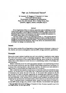
are defined in order to support the most interesting scenarios arising in a measurement sessions. In particular, the following policies have been defined to synchronize data transfers among devices: (i) joined, repeated, sequential task execution, (ii) optimistic and pessimistic readers/writers, (iii) dynamic priority readers/writers, (iv) producer/consumer, and (vi) support for active devices synchronization (scaling from single internal thread to a cooperating pool of k threads). AS far as the synchronization conditions are concerned, the architecture provides the basic conditions to be aggregated in order to build more complex conditions. They can be used in association with existing or new synchronization policies. The basic implemented conditions are related to field read/write events, operation execution or invocations and well-defined role operation execution events. The resulting architecture is extensible since concrete aspects implementing specific synchronization policies can be added easily and designed to implement new kind of policies such as needed. The added policies only need to implement interface and concrete mapping logic to intercept the client contexts. The architecture also foster reusability since existing policies can be reused in several different contexts and the synchronization logic is completely decoupled from the client code. III. A case study of motor synchronization An example for synchronizing ‘start’ and ‘stop’ operations on two motors with current measurements on two multimeters is highlighted in Fig. 2. The synchronization is achieved by means of the two aspect policies: “JoinSynchronization” and “TimerSynchronization”. The former implements a simple joining policy: when a ‘start’ operation is executed on the first motor, the related call is intercepted and queued internally in the aspect (and the corresponding thread put ‘to sleep’) until the other motor is also started. The latter policy TimerSynchronization implements a discrete timer: a queue of OperationCondition is associated to a timestamp and executed when the timestamp is reached. The public interface of the aspect JoinSynchronization allows synchronized actions to be added and the kind of synchronization condition to be specified (such as, method execution, read/write operation ordering on fields, mutual exclusion for operations). In the above example, two motors are created and added to a “join” synchronization group and a start operation is specified as synchronization element. This means that start operations on motors belonging to the synchronization group are intercepted and “handled” in a special way (the first one is queued while the last one starts the entire group).
Figure 2. An example of synchronization for ‘start’ operations on two motors in a FFMM demo.
16th IMEKO TC4 Symposium Exploring New Frontiers of Instrumentation and Methods for Electrical and Electronic Measurements Sept. 22-24, 2008, Florence, Italy
The public interface of TimerSynchronization interface is based on the execAtTiming service allowing users of the testing environment to specify OperationConditions to be executed mandatorily at specified time instants. Once configured, the aspect TimerSynchronization must be managed by using the start/stop/setTiming methods. The TimerSynchronization can be configured to work in AUTO or MANUAL modes. In the former mode, the timer is configured with a starting time and a time increment (with a resolution of 1ms). When a time interval, specified by execAtTiming, is passed, the queue of OperationConditions is executed. In MANUAL mode, a script is responsible for setting the right time on the timer when discrete interesting events happens so that the execution of OperationConditions associated to the timestamp is needed. In such a straightforward example, the JoinSynchronzation aspect is responsible for synchronizing both the start and stop operations capturing the corresponding method executions on the motors. After the last stop operation is called, the entire group of synchronized motors is stopped at the same time. The TimerSynchronization is needed to synchronize two multimeters, each one with an OperationCondition measuring the current in well defined time instants (the first every 100 ms, the second every 200 ms). An excerpt of the source code for this case study is shown in Fig. 3. The Synchronizer aspect reported in Fig. 3 defines abstract pointcuts to capture synchronizable elements. It refers to a policy interface to be customized in concrete sub-aspects (not shown due to space constraints). The Synchronizer aspects are singleton, thus a special mapping from the single aspect instance to each group of synchronized instances has been implemented. IV. Prototype of the AOP synchronizer for superconducting magnet tests at CERN The proposed AOP architecture for a synchronizer is applied to an automatic measurement system for testing superconducting magnets of the Large Hadron Collider under development at CERN in cooperation with the University of Sannio. In this context, an AOP-based task synchronizer is implemented in order to handle the software synchronization events in the rotating coil-based measurement, used to measure the magnet field parameters [12]. In the following scenario, the use of the proposed architecture is shortly described. // Test Session main procedure - Create MotorDevice objects and put in a JoinSynchronization group EPOS2KMotorDevice motorA = new … EPOS2KMotorDevice motorB = new … MultimeterDevice multimeter1 = new … MultimeterDevice multimeter2 = new … Synchronizer.aspectOf().addPolicy(“motorGroup”,JoinSynchronization.aspectOf()); Synchronizer.aspectOf().setCondition(“motorGroup”, Synchronizer.TASKSTART); Synchronizer.aspectOf().addPolicy(“multimeter1”,TimerSynchronization.aspectOf()); Synchronizer.aspectOf().setCondition(“multimeter1”,Synchronizer.OPERATIONCONDITION,AUTO); Synchronizer.aspectOf().execAtTiming(“multimeter1”,0,100,new OperationCondition(readCurrent1)); Synchronizer.aspectOf().addPolicy(“multimeter2”,TimerSynchronization.aspectOf()); Synchronizer.aspectOf().setCondition(“multimeter2”,Synchronizer.OPERATIONCONDITION,AUTO); Synchronizer.aspectOf().execAtTiming(“multimeter2”,0,200,new OperationCondition(readCurrent2)); Synchronizer.aspectOf().addAction(“motorGroup”, motorA); Synchronizer.aspectOf().addAction(“motorGroup”, motorB); // Configure multimeters; Multimeter1.configure(); multimeter1.selfTest(); multimeter2.configure(); multimeter2.selfTest(); // Configure and start motor A. motorA.configure(); motorA.selfTest(); motorA.start(); // Configure and start motor B. motorB.configure(); motorB.selfTest(); motorB.start();
Figure 3. Excerpt of the Motor Synchronization example with Join-Synchronization policy.
16th IMEKO TC4 Symposium Exploring New Frontiers of Instrumentation and Methods for Electrical and Electronic Measurements Sept. 22-24, 2008, Florence, Italy
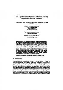
A coil turns in the magnet under test and its output signal is proportional to the flux derivative, according to Faraday’s law. The coil signal is integrated in the angular domain by means of the output pulses of an encoder mounted on the rotating coil shaft. A Fourier analysis of the flux yields finally the multipoles of the magnetic field generated by the magnet under test. A workstation is used to remotely control the motor movement, the magnet power supply, the coil signal acquisition and integration, and the current measurement. By means of the rotating coils technique, two kinds of test can be performed on the LHC superconducting magnets: (i) at room temperature (warm condition), by limiting the current in the magnet to 10 , and (ii) at 1.9 K (cold condition), by supplying the magnet with an LHC current cycle (500 A up to 14 kA). The architecture of the measurement system is shown in Fig. 4. Digital Multimeter Two Ethernet cabels (Rx/Tx) (Fast Ethernet IEEE802.3.u)
GPIB PC Management station
PXI-8570
POWER CONVERTER
PXIS-3320 chassis
Single FDI
WorldFIP Getaway
RS232
Encoder Board
WF Bus
FGC1
Ethernet Cable Motor Controller
12 compensate signals 12 absolut signal A pair to each FDI
(20A) Power Supply
Pipes
μ RU
MAGNET UNDER TEST
Anti-cryostat Rotating coils shaft Portable DCCT
Only in warm conditions
Figure 4. Architecture of the on-field test station. The main goal of the test is the commissioning [12] of (i) the new rotating coils transducers, (ii) the new Fast Digital Integrator (FDI), and (iii) the new software, all developed at CERN. Normally, the field analysis on each of the two pipes of the magnet is carried out by means of a maximum of 24 FDIs, integrating the signals produced by coils placed in 12 sections in which the magnet is divided. Two FDIs are required for the analysis on each section. For this preliminary test at warm condition, only three sections of one pipe are used, for a total of 6 FDIs. The measurement software is able to manage more than one FDI, by providing the tools to start the acquisition and retrieve the raw data on the required number of integrators. test_script() { GPSDevice _time FastDI _absoluteDI FastDI _compensatedDI
= new GDSDevice("GPS1");; = new FastDI("I1"); = new FastDI("I2");
... Synchronizer.aspectOf().execAtTiming(1,new Synchronizer.aspectOf().execAtTiming(1,new Synchronizer.aspectOf().execAtTiming(1,new Synchronizer.aspectOf().execAtTiming(2,new Synchronizer.aspectOf().start();
OperationCondition(readTime)); OperationCondition(readAbsolute)); OperationCondition(readCompensated)); OperationCondition(readTime));
... } void readAbsolute() { FastDI::getFDIDataLogger("I1"). add(getDevice("absolute_integrator").getTime(),getDevice("absolute_integrator").getCount());} void readCompensated() {FastDI::getFDIDataLogger("I2").add(getDevice("absolute_integrator").getTime(), getDevice("compensated_integrator").getCount()); } void readTime() { TestManager::addTimestamp(getDevice("GPS1").getTime()); }
Figure 5. Synchronization in the code for the rotating coil measurement application.
16th IMEKO TC4 Symposium Exploring New Frontiers of Instrumentation and Methods for Electrical and Electronic Measurements Sept. 22-24, 2008, Florence, Italy
A software system capable of performing the above-described measurement procedure involves many different devices. Some instrument features can be implemented as separated tasks, running asynchronously, but nonetheless respecting some sequence constraints related to the rotating coils measurement procedure. In Fig. 5, a fragment of the code for the synchronization in the rotating coilsbased measurement system is shown. In this case, a TimerSynchronization is used in mode MANUAL to schedule read operation on the digital integrators (the FDIs). The software task synchronizer therefore ensures a correct overall execution of the given procedure. The user can set some significant time instants, at which some predefined actions have to be performed. The aspects managing synchronization tasks will take in charge for those actions. V. Conclusions The AOP-based architecture proposed in [11] for implementing synchronization in automatic measurement systems has been enhanced. A more complex and realistic case study, including also multimeters, was proposed. A first AOP prototype is under development in a measurement station for testing superconducting magnets at CERN. Experiments to assess the main advantages about improved maintainability and reusability of the measurement software system are being to set up and carry on. References [1] Graunke, G. and Thakkar, S. Synchronization algorithms for shared-memory multiprocessors. In Programming Languages For Parallel Processing, D. B. Skillicorn and D. Talia, Eds. IEEE Computer Society Press, Los Alamitos, CA, 26-35, 1995. [2] Gupta, R. K., Coelho, C. N., and De Micheli, G. “Synthesis and simulation of digital systems containing interacting hardware and software components”. In Readings in Hardware/Software Co-Design, G. De Micheli, R. Ernst, and W. Wolf, Eds. The Morgan Kaufmann Systems On Silicon Series. Kluwer Academic Publishers, Norwell, MA, 544-549, 2001. [3] C. von Praum, H. W. Cain, J. Choi, K. D. Ryu, “Conditional Memory Ordering”, in Proc. of the 33th International Symposium on Computer Architecture (ISCA), IEEE, 2006. [4] S. Wang, K. G. Shin, “Constructing reconfigurable software for machine control systems”, IEEE Trans. on Robotics and Automation, Vol. 18, N. 4, pp. 474-486, Aug. 2002. [5] J. M. Nogiec, J. DiMarco, S. Kotelnikov, K. Trombly-Freytag, D. Walbridge, M. Tartaglia, “A configurable component-based software system for magnetic field measurements”, IEEE Trans. on Applied Superconductivity, Vol. 16, N. 2, pp. 1382-1385, Jun 2006. [6] J. E. Beck, J. M. Reagin, T. E. Sweeney, R. L. Anderson, T. D. Garner, “Applying a componentbased software architecture to robotic workcell applications”, IEEE Trans. on Robotics and Automation, Vol. 16, N. 3 pp. 207-217, Jun. 2000. [7] N.R. Jennings, “Agent-based computing: promises and perils”, Proc. of the fifth International Joint Conference on Artificial Intelligence (IJCAI), pp. 1429-1436, 1999. [8] C. Pfister, C. Szyperski, “Why objects are not enough”, Proc. First International Component Users Conference (CUC), Jul. 1996. [9] G. Kiczales, J. Lamping, A. Mendhekar, C. Maeda, C. Videira Lopes, J.M. Loingtier, J. Irwin, “Aspect-Oriented Programming”, in Proc. of the 11th European Conf. on Object-Oriented Programming (ECOOP), Vol. 1241, pp. 220-242, Springer-Verlag, 1997. [10] P. Arpaia, M. Bernardi, G. Di Lucca, V. Inglese, G. Spiezia, “Fault Self-Detection of automatic testing systems by means of Aspect- Oriented Programming”, in Proc. of the 15th IMEKO TC4 Symposium, Iasi, Romania, Sept. 2007. Invited for submission on Computer, Standards & Interfaces, Elsevier. [11] P. Arpaia, M. L. Bernardi, G. Di Lucca, V. Inglese, G. Spiezia, “Aspect Oriented-based Software Synchronization in Automatic Measurement Systems”, IEEE IMTC, Victoria, Vancouver Island, Canada, May 12–15, 2008. [12] P. Arpaia, L. Bottura, V. Inglese, G. Spiezia, “Preliminary Experimental Validation of the New Platform for Magnetic Measurements at CERN”, accepted on Measurement.