Berkeley, CA. Abstract. This paper discusses a model-based design flow for re- quirements in distributed embedded software development. Such requirements ...
SoftContract: an Assertion-Based Software Development Process that Enables Design-by-Contract Jean-Yves Brunel Cadence Automotive Team Paris, FR
Marco Di Natale Scuola Superiore Sant’Anna Pisa, IT
Paolo Giusto Cadence Automotive Team San Jose, CA Abstract This paper discusses a model-based design flow for requirements in distributed embedded software development. Such requirements are specified using a language similar to Linear Temporal Logic which allows one to reason about time and sequencing. They consist of assertions which must hold for a design, given some assumptions on its environment. They can be checked both during simulation and, at least for a subset, even on the target. The key contribution of the paper is the extension to the embedded software domain of assertion-based verification, and the automated generation of property-checking code in multiple target languages, from simulation, to prototyping, to final production.
1. Introduction Today, car manufacturers provide specifications to subsystem suppliers, who design software and hardware subsystems that may include mechanical parts (e.g. injectors and throttle bodies). In general, volumes are large, cost and dependability being major driving forces. Once the subsystems are provided back to the car manufacturers, they have to be integrated on the car and then the overall system must be tested. If the car manufacturer detects errors during the extensive testing period, which includes driving under extreme conditions, a chain of engineering changes is initiated that may (and it often does!) cause major delays in the design. Such problems are traceable for the most part to software errors [14], because of incorrect understanding of the specifications and unpredictable side effects when the subsystems are interconnected. The loop is particularly painful since testing is done when the car is almost ready for its launch on the market.
1530-1591/04 $20.00 (c) 2004 IEEE
Alberto Ferrari PARADES Roma, IT
Luciano Lavagno Cadence Berkeley Labs Berkeley, CA This paper addresses directly this issue, and discusses a model-based design flow for properties in distributed embedded software design, thus extending the traditional accepted model-based design paradigm. The proposed methodology supports the definition of requirements on the performance and dependability of a real-time distributed system, as well as the validation that they are met in the fully implemented system. In this context, we first consider applications of automotive electronics that set stringent requirements in particular on dependability attributes such as safety, availability, maintainability, and also confidentiality, due to the complexity of its design chain. Current model-based design flows, such as those based on Ascet-SD [2] or Simulink [13] specifications and RealTime Workshop Embedded Coder [13] or TargetLink [5] implementations, emphasize automated transformations of specifications early in the design cycles, therefore reducing the risk of incorrect implementations. Yet they neglect automated transformations of properties. The basic tenet of the proposed novel flow is that both functional (e.g. relating I/O values) and non-functional (e.g. specifying performance requirements) properties, must be stated formally at the highest possible level in the flow, immediately deriving them from the informal requirements captured in a natural language. The traditional mechanism for representing functional and some non-functional properties, e.g. I/O rates, is the definition of a testbench, which verifies operationally that the properties are satisfied. This method is not efficient, because it is too implicit, non-declarative and partial. Constraints that a design must satisfy are decomposed, checked and propagated along the design flow, whether it uses a top-down, bottom-up or V-cycle path including specification, implementation and integration. In particular, propagation entails automated transformation from one domain to another when crossing levels of abstraction (e.g.
temporal logic formulae translated into simulation monitors and then into on-line error-checking software). Decomposition and checking, on the other hand, enable a clean design by contract between different parties involved in different design levels (e.g. system architect and software designer). The goal of contract-based design is speeding up dramatically the design and improve the quality of embedded systems. The former is achieved by enabling a clear communication of requirements between various parties involved in the specification, design and validation of embedded systems. The latter is obtained by describing and automatically tracking satisfaction of constraints throughout the design flow, including post-production and on-line (run-time) checking, in a formal way.
1.1. Previous work Past work in this area, which traditionally belongs to the formal and semi-formal verification methods, can be identified both on the hardware and on the software side. On the hardware side, assertion-based verification is emerging as a promising evolutionary method to introduce formal techniques to specify and check properties starting from the Register Transfer Level, as opposed to merely checking equivalence between optimized and unoptimized designs or between layout and netlist. Recent standardization efforts, such as the PSL proposal by Accellera [8], aim at defining languages that are close to the way in which designers are used to model, e.g. Verilog and VHDL, and which provide a full range of options including full temporal logic, both in untimed (e.g. every request shall eventually be granted) and timed (e.g. every request shall be granted within 15 clock cycles) forms. The Rosetta work [1] also aimed at defining a very generic mechanism, based on sets and logics, to reason about properties of hardware designs. On the software side, the Object Management Group has standardized the Object Constraint Language, which has similar goals, i.e. to precisely state requirements that objects, scenarios and software systems modeled in the Unified Modeling Language must satisfy. The OCL, however, is very expressive, and suffers from the lack of a standard executable semantics for the UML (which should be added in the upcoming UML 2.0 standard, also from the OMG). Thus it becomes suitable for automated checking and decomposition only if an application-dependent subset is chosen by a specific UML profile. For example, the proposed UML Profile for Schedulability, Performance and Time [6] defines a subset of the OCL that can be used for representing deadlines, execution times, usage of shared resources and so on. Other non-standard attempts at enriching the UML with timing notations include [9, 12], while [3] proposed an integrated environment for expressing functional
and non-functional constraints. Finally, [7, 10, 11] describe Real-Time Logics (RTL) and a toolset to reason about temporal aspects of real-time systems, but do not attempt to transform them between levels of abstraction. In this work we use the Logic Of Constraints [4], which is a language reminiscent of various temporal logics (CTL, LTL and RTL) and which has been developed specifically to reason about various quantitative aspects of an embedded system (not just time). LOC is useful for our purposes, because it can be translated into simulation monitors for onthe-fly checking, rather than requiring full-fledged model checking, which suffers from inherent state explosion problems. Moreover, its semantics is based on sequences of events over signals, and it is thus easy to use for designers who are familiar with tools such as Simulink. This proved to be a key advantage with respect to more classical temporal logics such as CTL and LTL, which were designed more with protocol verification in mind. LOC moreover allows one to associate and reason about any annotation, not just time but also e.g. energy or memory, with events in the system.
1.2. Terminology A design is a modeled piece of hardware and/or software, which must be implemented as a result of the design activities. A design can be represented as a structure, i.e. a collection of components (also called modules or blocks) connected via nets to each other’s ports (mechanisms to communicate between blocks, such as shared variables or messages). Each component, and thus eventually the whole design, may have a functional model, describing how its output ports relate over time with its input ports. Both structure and functionality are described using any appropriate modeling language such as C, StateCharts, Simulink, Verilog, VHDL, and so on. An event is an update of value (not necessarily a change of value, i.e. the updated value may be the same as the old one) of a port of a module of the design. For example, the arrival of a value from a sensor, the decision to change the state of a design component, or the generation of a command to an actuator are all events. Each event is annotated with a time of occurrence, and optionally with other quantities (such as energy) for which constraints can be specified. This black-box semantics is essential for efficient implementation and decomposition, since prematurely exposing information about internal aspects of a design leads to poor portability, modifiability, re-usability, verifiability and optimizability. Black-boxing also improves security of a company’s Intellectual Property, by hiding implementation details. The environment of a design is a part of the whole system which cannot or need not be implemented by the con-
sidered team (e.g. the engine for the electronic control unit implementors, or the sensor sample conditioning filters for the control algorithm implementors). In other words, this paper considers a design flow in which the top-level model is (recursively) decomposed into sub-models, whose design must be carried out by different teams or individuals, possibly belonging to different companies. A property is LOC formula, involving events and their annotations (e.g. time of occurrence), which must be true, and which can play different roles depending on the context. An assertion is a property which must be guaranteed to hold by a design. For example, the statement that the latency between an input and an output event must be less than 0.1 msec is an assertion. An assumption is a property which limits the set of environment behaviors to be considered, and thus exhibits some freedom that can be exploited by knowing that some cases can never occur. For example the statement that the maximum rate of arrival of input events is 1 per msec is an assumption. Quite often, a requirement on a design component is expressed as a pair including: an assertion that is assumed by users of the component to hold, and guaranteed by its implementer to hold, and an assumption that is assumed by the implementer of the component to hold, and must be guaranteed by its users to hold, as illustrated by the following simple example. First of all, the designer in charge of assigning priorities to tasks running on a real-time executive can make assumptions on the maximum rate of arrival of events triggering them and on their WCET, and must satisfy assertions on the priority ranking (e.g. based on Rate Monotonic Analysis). Then the team who is in charge of implementing the tasks can make assumptions on the maximum rate of arrival of events and on priorities, and must satisfy assertions on their WCET. Finally, the integrator of the control unit in the car can assume priorities and WCETs and must satisfy assertions on event arrival rates. A monitor finally is a component of a design whose main task is to verify that an assumption or an assertion on another component or set of components is satisfied. Monitors are executable checkers that can be used in simulation, prototyping and production code in order to ensure that the design contracts are respected.
related with timing, are checkable only when the functional model has been annotated with performance information, so that the time information attached to events reflects the effects of the underlying architecture. These requirements can be used both bottom-up and topdown. Bottom-up, they clearly specify the contract that the implementer promises to obey with respect to the users of a component. Assertions are guaranteed provided that assumptions are satisfied (e.g., this piece of software written in C computes the response with a precision of 1% provided that “int” variables have at least 32 bits). Top-down they specify requirements that the implementer must obey, and state the assumptions he can make on the users of the component. An essential aspect of a bottom-up design flow is the composition of assertions on individual components, while checking that the used components guarantee each other’s assumptions. A full-fledged compositional proof methodology would require theorem proving, an expensive proposition today even for safety-critical applications. More practically, monitors can be used to trace the requirements throughout the lifetime of a component. For example, governments have imposed regulations for the automotive industry that limit the level of chemical emissions from car engine exhausts. In order to comply with these regulations, a vehicle must satisfy the European On Board Diagnostics, a standard which imposes a set of properties of the system that must hold and are checked at run-time. This is implemented through a set of monitors allocated to the different electronic control units, which check relevant values of the state of the software (variables). These monitors are typically coupled with other components that implement recovery and logging in case of violations. In top-down design, on the other hand, requirements on the global I/O of the system are decomposed into subproperties that must hold for each component of the design. The collection of sub-properties on other components, not under design by a specific team, together with assumptions on the global top-level environment, become the set of assumptions that an implementer can make on his component’s environment, as illustrated in Section 3.
2. Design flow
2.1. Property specification language
In the proposed design flow, the requirements on a design are first specified as assertions which must hold, given some assumptions on its environment. In order to be able to define such assertions and assumptions, one must have defined a skeletal structure for the design, at the very least the I/O ports with which it communicates with its environment. Assertions are checkable only when the functionality of the design has been specified. Some of them, e.g. those
Logic Of Constraints [5] is a formalism designed to reason about execution traces. It consists of basic relational, Boolean and implication operators, with additions that make it possible to specify system level quantitative functional and performance constraints without compromising the ease of analysis. The basic components of an LOC formula are: events (defined above), the index variable and annotations:
1. Annotation: each event may be associated with one or more annotations. Annotations can be used to denote the time, power, area, or any value related to the event. �������� denotes the annotation (by conE.g., Display vention time, while annotation represents its value) �� � of the -th event of the Display port. 2. Index variable: LOC permits only one event index variable , a positive integer, in a given expression (the limitation helps ensuring checkability in bounded memory). Index expressions of events may be any arithmetic operations involving and con�� ���
� stants, e.g. Display , Stimuli . LOC can be used to specify some very common and useful real-time performance constraints:
� rate: E.g. “Displays are produced every 10 time units”:
��� �� �������� �������� Display
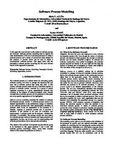
Figure 1. The adaptive cruise control application
Display
� latency: E.g. “Display is generated no more than 25 time units after Stimuli”:
��� ��
��� �������� Display Stimuli For a LOC formula to be formally proven for a design, it needs to hold for all possible traces and all values of the index , as it appears in the index expressions of the formula. For a formula to be checked for a particular simulation trace, it needs to hold for that trace only and all values of . In the rest of the paper we are concerned only about checkability.
2.2. Target language translations
is expensive to check in the target system. Hence it is recommendable to keep until implementation only local assertions (which refer to ports of a single component), and assertions related only to time, e.g. those modeling scheduling deadlines and assumed worstcase execution times, which can be checked by timers and watchdogs.
� Off-line and on-line hardware-assisted property checkers, using in-circuit debuggers or on-chip real-time tracers. The hardware resources provided by the these devices strongly limit the number and complexity of the properties that can be concurrently checked.
The properties specified using the language above can be translated automatically, into:
� Off-line database query code, which checks that both assertions and assumptions are satisfied on a given set of simulation traces. Probes are automatically generated and instantiated in order to collect enough information to answer the queries corresponding to all the properties being checked. The example described in Section 3 was checked in this off-line mode of design by contract.
� On-line monitor modules written in whatever simu-
lation language is used for design verification. These monitors emit error messages when the assertion or assumption is violated, as well as a warning at the end of the simulation if an assertion or assumption is neither satisfied nor violated.
� On-line code to be integrated within the software tasks,
to which the ports referenced in the property text belong. Note that any property that allows the RTOS to inspect the state of a running task, or that relates values of variables of different mutually asynchronous tasks,
3. A design example For the sake of illustrating our proposal, we describe an example of a safety critical application, typically implemented on a distributed multi-cluster ECU architecture. The application is a simplified version of an Adaptive Cruise Control (ACC), shown in Figure 1. The ACC includes “regular” cruise control features, but must also automatically decrease the speed of the vehicle, if an obstacle is detected at a distance less than the safety distance threshold. In this case, actuation signals are automatically sent to the brake system and to the engine control system. The functional model that we used includes models of the driver, the radar system, the engine, and the brake. The ACC algorithm determines the gas pedal position (therefore replacing the driver) based upon the vehicle speed, the distance between the vehicles, and their relative speed. The control strategy is defined by the ACC Finite State Machine. Based on choices from the driver, it decides which position of the gas pedal is provided to the engine control.
3.1. Some simple properties An important safety feature of our algorithm, that can be used to test the contract-based design flow, is that the current value of the gas pedal is retained in case the new position determined automatically is very different (for example due to data corruption) from the current one. This is expressed by the following LOC property: define limit_change (comp, act, thr) { abs (comp[i].v - act[i-1].v) > thr -> act[i].v == act[i-1].v }
instantiated as the following requirement (assumption plus assertion): assume FSM.State[i].v == ACCon assert limit_change (FSM.GasPedalPositionFSM, FSM.GasPedalPositionACC, FSM.threshold);
Here FSM is the name of the block whose inputs and outputs are used in the property, state is a viewport exposing its state, GasPedalPositionACC is the output of the automated cruise control block (and input to the FSM block) which determines the required position to decelerate smoothly when required, GasPedalPositionFSM is the output of the FSM block which goes directly to the actuator, and threshold is a parameter which must be tuned on the prototype car in order to provide a smooth and safe driving experience. Finally, -> denotes logical implication Another assertion that was checked in this design, using the LOC database monitors, is the following: if the distance between vehicles goes below a given threshold, then within 30 seconds the distance will be again above threshold.
semantics, and assumptions on the rate establish the relationship between invocations and time. For example, since the ACCCore model is invoked once every millisecond and the tolerance tol on the invocation rate is 1%, the index difference 30 / 0.001 refers to a time interval of 30 seconds plus or minus 1%. Debounce assertions are important to correctly evaluate Boolean signals produced by the environment. When a switch is pressed, the output signal oscillates until it reaches a new stable value. The debouncing functionality guarantees that only the final value of the switch signal is used as input value. In our example, the switches that turn on and off the cruise control and the adaptive feature must be debounced before evaluation. The requirements to debounce a switch in a time window of 200ms can be expressed as follows: event EdgeSwitch { Switch[j-1].v!=Switch[j].v } assert EdgeSwitch[i+1].t-EdgeSwitch[i].t > 0.2;
This example uses an “event definition” facility of LOC, which allows one to define new events based on the occurrence of logic and relational conditions on existing events.
3.2. Assertion/assumption decomposition We will now consider an example of how decomposition of assertions into pairs of assumptions and assertions can be used to define and verify the interface between two teams or companies working on two portions of the system. The adaptive cruise control must guarantee a certain degree of comfort during cruise. For instance the vehicle should not accelerate or decelerate, ����� after reaching the cruising speed, , which can be expressed with the by more than a 0.5 following assertion:
define rate (g, thr, tol) { abs (g[i].t - g[i-1].t) < thr + thr * tol and assert FSM.State[i].v == ACCon => abs (g[i].t - g[i-1].t) > thr - thr * tol) } abs(Acceleration[i].v) < 0.5; define slowdown (dist, thr, delta) { The overall system, as shown in Figure 1, is decomposed dist[i-delta].v < thr -> dist[i].v >= thr; }
into ACC, Engine control and Brake control. The ACC proassume ACCCore.Speed - Radar.OtherVehSpeed < 10 vides the gas pedal position to the Engine control, which and rate (ACCCore.speed, 0.001, 0.01) translates it to a request for a given amount of torque. The assert slowdown (ACCCore.distance, Engine finally produces the torque. The previous assertion, ACCCore.threshold, 30 / 0.001); checked at run-time, would inform the designer if a viola-
Here we assume that the difference between vehicle speeds is less that 10m/s, otherwise, the only safe option for the driver is to brake by himself (this is not a drive-by-wire system, only an enhanced cruise control). Here ACCCore.speed is the speed of the current vehicle (an input to the ACC controller ACCCore), Radar.OtherVehSpeed is the speed of the other vehicle, as measured by the Radar, distance is their distance and threshold is a parameter defining the distance at which the speed must begin to be reduced. Time is measured here in terms of discrete controller invocation intervals, which is consistent e.g. with the Simulink
tion on the vehicle acceleration occurred, but would not explain if this was due to a design error of the engine control or of the ACC control. If the two control units are built by different sub-system makers, it would be problematic to pinpoint the cause of the error in the design. Following our methodology, the assertion should be decomposed into three parts: (1) an assertion on the torque requested by the ACC, (2) an assertion on the torque provided by the Engine control and the engine, and (3) an assertion on the relation between vehicle acceleration and torque. The third assertion is always satisfied in a given gear, since it checks the inputs and outputs of a mechanical system, that is the powertrain of the vehicle. In this case, a torque
smaller than 20 ensures an acceleration smaller than 0.5. The first assertion on the behavior of the ACC can thus be expressed as follows: assert FSM.State[i].v == ACCon => abs(ACC.TorqueRequest[i].v) < 20;
The Engine control unit maker is using the same property as an assumption, instead of an assertion, checking that the torque request, when the cruise control is on, is limited as specified and agreed. The second assertion thus is expressed as follows: assume FSM.State[i].v == ACCon and abs(ACC.TorqueRequest[i].v) < 20 assert abs(Engine.Torque[i].v) < 20;
A violation of the vehicle acceleration is now shown by different checkers, and the sub-system causing the violation is easily found, even before system integration. The design described here was created using the Cadence Automotive System Design Platform (also known as SysDesign). Plant models were imported from Simulink via a special Real-Time Workshop target. The Engine control model along with the task structure was imported from Ascet-SD [2], a model based design environment for algorithmic development, with code generation capabilities for both prototype and target. The definition of the target multiECU architecture, the task allocation to the ECUs, the bus modeling and the simulation were performed in SysDesign. Properties were checked automatically using a tool which compiles the LOC formula into a fragment of C code which reads the SysDesign simulation database and checks the validity of the formula off-line over a simulation run.
4. Conclusions This paper proposes a model-based design flow for assertions and assumptions that together ensure the correctness, both functional and non-functional, of a complex embedded system. The paper uses examples, terminology and scenarios from the automotive software domain, but the flow is applicable to any safety-critical mixed hardware/software system. Assertion-based verification is becoming a cornerstone of hardware design. What is new in the case of safetycritical embedded systems is the extension to the software domain of assertion-based verification, and the automated generation of code in multiple target languages, from simulation database queries, to simulation monitors, to prototyping, to final production. This leads to:
� faster time-to-market, by reducing design iterations,
� real contract-based design between specifiers (system architects), implementors (software designers) and integrators, by allowing
– fast verification by the sub-system providers that the assertions made by the architect on sub-systems are satisfied and – delivery of partial assumptions and assertions from sub-system providers to system integrators for earlier verification of end-to-end assertions.
� faster implementation, thanks to automated target code generation for assumption and assertion checking,
� safer implementation, due to the formal property specification mechanism. In the future we are planning to explore the use of assertions and assumptions for automated testbench generation, e.g. by constraint solving.
References [1] P. Alexander, C. Kong, and D. Barton. Rosetta usage guide. http://www.sldl.org. [2] ETAS Ascet-SD. http://www.etas.de. [3] A. Burns and A. J. Welling. HRT-HOOD: A design method for hard real-time. Journal of Real-Time Systems, 6(1):73– 114, 1994. [4] X. Chen, H. Hsieh, F. Balarin, and Y. Watanabe. Automatic generation of simulation monitors from quantitative constr aint formula. In Proceedings of Design Automation and Test in Europe, March 2003. [5] dSPACE TargetLink. http://www.dspace.de/. [6] Object Management Group, editor. UML Profile for Schedulability, Performance, and Time. OMG document ptc/02-0302, 2002. [7] F. Jahanian and A. Mok. Modechart: a specification language for real-time systems. IEEE Transactions on Software Engineering, 20(12):933–947, 1994. [8] Accellera Property Specification Language. http://www.accellera.org/. [9] J.L. Medina, M. Gonzalez Harbour, and J.M. Drake. Mast real-time view: A graphic uml tool for modeling objectoriented real-time systems. In Proceedings of IEEE RealTime Systems Symposium, December 2001. [10] A. Mok and G. Liu. Early detection of timing violation at runtime. In Proceedings of IEEE Real-Time Systems Symposium, December 1997. [11] C. Puchol and A. Mok. Integrated design tools for hard realtime systems. In Proceedings of IEEE Real-Time Systems Symposium, December 1998. [12] M. Saksena, P. Freedman, and P. Rodziewic. Automated implementation of executable object oriented models for realtime embedded control systems. In Proceedings of IEEE Real-Time Systems Symposium, December 1997. [13] The Mathworks Simulink and StateFlow. http://www.mathworks.com. [14] USA Today. Advances in car technology bring high-class headaches, November 2003. http://www.usatoday.com/tech/news/2003-11-11carrepairs x.htm.