An Automatic Portrait System Based on And-Or Graph Representation Feng Min1,4 , Jin-Li Suo2,4 , Song-Chun Zhu3,4 and Nong Sang1 1
IPRAI, Huazhong University of Science and Technology, China. 2 Graduate University of Chinese Academy of Sciences, China. 3 Departments of Statistics and Computer Science, University of California. 4 Lotus Hill Institute for Computer Vision and Information Science, China.
[email protected],
[email protected],
[email protected],
[email protected]
Abstract. In this paper, we present an automatic human portrait system based on the And-Or graph representation. The system can automatically generate a set of life-like portraits in different styles from a frontal face image. The system includes three subsystems, each of which models hair, face and collar respectively. The face subsystem can be further decomposed into face components: eyebrows, eyes, nose, mouth, and face contour. Each component has a number of distinct sub-templates as a leaf-node in the And-Or graph for portrait. The And-Or graph for portrait is like a ”mother template” which produces a large set of valid portrait configurations, which is a ”composite templates” made of a set of sub-templates. Our approach has three novel aspects:(1) we present an And-Or graph for portrait that explains the hierarchical structure and variability of portrait and apply it into practice; (2) we combine hair, face and collar into a system that solves a practical problem; (3) The system can simultaneously generate a set of impressive portraits in different styles. Experimental results demonstrate the effectiveness and lifelikeness of our approach. Key words: And-Or Graph, Non-Photorealistic Rendering, Face
1
Introduction
A portrait is a concise yet expressive representation of each person. A life-like portrait should not only resemble the appearance of an individual, but also capture the spirit of an individual. It is a difficult and challenging task to automatically generate a life-like portrait from a given face image. There have been a few attempts to interactively or automatically generate a stylistic facial sketch by observing images drawn by artists. For example, a few template-based facial caricature systems were developed by Koshimizu et al [1] and Li et al[2], which simply linked face feature points using image processing methods and produced stiff sketches. A number of example-based approaches have been proposed for sketch. For instance, Librande[3] developed an example-based character drawing system. Freeman et
2
Lecture Notes in Computer Science: Authors’ Instructions
al[4] presented an example-based system for translating a sketch into different styles. With the development in texture synthesis[5] and face hallucination[6], Chen et al [7, 8] developed an example-based face sketch generation system. They used inhomogeneous non-parametric sampling to capture the statistical likelihood between the sketch and original image, and fit a flexible template to generate the sketch. However, this method is the mapping from image to sketch, it is difficult to change the style of portrait. Inspired by recent development in generative model[16, 9], Xu et al [10] presented a high resolution grammatical model for face representation and sketching. They adopted three-layer generative model and coarse-to-fine computation to generate fine face sketches. Chen et al [11, 12] presented a generative model of human hair for hair sketching and composite templates for cloth modeling and sketching. These models can generate vivid sketches of hair, face and cloth, however, no one combines these separate parts into one portrait system. In this paper, we present an automatic portrait system based on the And-Or graph representation. We build an And-Or graph for portrait which can account for the variability of portraits by separating the structure and style of portrait. Additionally, we build a set of sketch dictionaries for portrait components in different styles. With the And-Or graph for portrait and sketch dictionaries, we can automatically generate a set of life-like portraits in different styles from a given face image as shown in Figure 10, 11. The rest of this paper is organized as follows. We introduce the And-Or graph for portrait in Section 2. The automatic portrait system is presented in Section 3. Experimental results are shown in Section 4. In Section 5, we will discuss the limitations of our approach and the future work.
AND
AND
Fig. 1. Decompose portrait into components.
Lecture Notes in Computer Science: Authors’ Instructions
3
Fig. 2. The variability of portrait components.
2
The And-Or Graph for Portrait
As is shown in Figure 1, a portrait includes three parts: hair sketch, face sketch, and collar sketch. The face sketch can be further decomposed into eyebrows sketch, eyes sketch, nose sketch, and mouth sketch. All of these components form a rather fixed spatial configuration within the face contour. At the same time, variability still exists in portraits, not only globally such as different views or posture, but also locally such as open/closed mouth or different types of hair. For example, Figure 2 shows various hair, collar, eyebrows, eyes, nose, mouth, and face contour together with their corresponding sketches.
4
Lecture Notes in Computer Science: Authors’ Instructions
We need to take three categories of variability into account. (1) Topological configuration, such as V/T collar; (2) Geometric deformation, such as thick/thin eyebrows; (3) Photometric variabilities, such as light/dark hairs. In order to account for these variabilities, we propose an And-Or graph for portrait. And-node
portrait
Or-node Leaf node
hair hair1
hairN
eyebrow eyebrow1
eyebrowN
collar
face face1
faceN
eye eye1
eyeN
nose nose1
collar1
face contour
mouth noseN
collarN
mouth1
mouthN
face contour1
face contourN
Fig. 3. The And-Or graph for portrait.
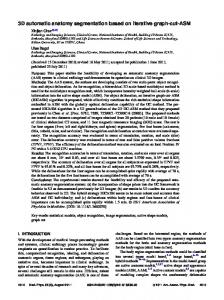
As is shown in Figure 3, each terminal(leaf) node represents a component or sub-template. Different sub-templates in the same category are represented by distinct subgraphs. The non-terminal nodes are either And-nodes whose children must be chosen jointly or Or-nodes of which only one child can be selected. An And-node is an instance of the semantic meaning, which expands the regularized configurations. An Or-node only has the syntax meaning, which is a switch between alternative sub-configurations. So the And-nodes, the Or-nodes, and the leaf nodes constitute an And-Or graph. The And-Or graph has horizontal dash lines to specify the spatial relations and constrains among the nodes. For example, hair is above the face, while collar is below the face. Eyebrows, eyes, nose, mouth are within the face contour. These relations and constrains help to link the components together to form a valid representation. Thus the AndOr graph is like a ”mother template” which produces a set of valid portrait configurations -”composite templates” that are made of a set of sub-templates. As a matter of fact, an And-Or Graph is a context sensitive grammar [13], which can be regarded as a 5-tuple Gand−or =< N = U ∪ V, T, Σ, R, A > Each element is explained as below:
(1)
Lecture Notes in Computer Science: Authors’ Instructions
5
1. Non-terminal nodes N = U ∪ V includes a set of And-nodes and Or-nodes. U = {u1 , ..., un }; V = {v1 , ..., vn }
(2)
An And-node u ∈ U represents a composite template, which is composed of a set of sub-templates. An Or-node v ∈ V is a switch pointing to a set of alternative sub-templates. 2. Terminal nodes T is a set of atomic templates. T = {t1 , ..., tn }
(3)
A terminal node t ∈ T represents an object component, which can’t be further expanded or decomposed. 3. Configurations Σ is a finite set of valid composite templates. Σ = {G1 , ..., Gn }
(4)
Each graph G ∈ Σ is a specific configuration for portrait. Σ includes all of the possible valid configurations. 4. Relations R is a set of relations between any two nodes in the And-Or graph. R = {r(ni ,nj ) =< ni , nj >; ni , nj ∈ N ∪ T }
(5)
Each relation represents the statistical constraint on the attributes of the nodes. 5. Attributes A is a set of attributes for each node in the And-Or graph. For the terminal nodes ti ∈ T , A is a set of photometric and geometric transforms. geo A = {(Apho (ti ) , A(ti ) ); i = 1, 2, ..., n}
3
(6)
The Automatic Portrait System
In order to automatically generate a set of life-like portraits in different styles, we need a large number of sub-templates in different styles as the terminal nodes. We asked artists to draw the portrait in different styles on top of the original image with a different layer in PhotoShop. Then we manually decompose the portrait into a set of components as is shown in Figure 1. By collecting these components, we build a large database for hair, collar, eyebrows, eyes, nose, mouth, face contour and their corresponding sketches in different styles. From this large database, we can extract different types of hair, face components, and collars to build a set of sketch dictionaries in different styles. It is also convenient to change the style of portrait by changing the sketch dictionaries. Based on the And-Or graph for portrait, we divide the portrait system into three subsystems: hair subsystem, face subsystem and collar subsystem. The face subsystem is the key part which can be further decomposed into face components: eyebrows, eyes, nose, mouth, and face contour. We detect face rectangle using a boosted cascade of features[14]. Then we adopt a local Active Appearance
6
Lecture Notes in Computer Science: Authors’ Instructions
Model (AAM) [15–17] for each face component. The hair subsystem and the collar subsystem are connected to the face subsystem. We first find the hair contour and the collar contour by the spatial relationships. Then we use shape matching to find the best matched shape with shape contexts [18]. Last we warp the best matching shape to the corresponding shape contour by the Thin Plate Spline(TPS) [19, 20] model. The details of the three subsystems will be presented in the following sections.
1 2 3 4 5 Fig. 4. The different types of facial components extracted from the database.
3.1
Face Subsystem
Because of the diversity in the database, we categorize the face components into four types of eyebrows, five types of eyes, five types of nose, four types of mouth, and two types of face contour shown in Figure 4. Each type of component has its own AAM. The AAM representation includes a set of principle components for the geometric deformations and a set of principle components for the photometric variabilities after aligning the landmarks. Therefore we build a dictionary for all (4+5+5+4+2=20) components and their corresponding sketches.
cp,i Igeo
cp,i Ipho
cp,i cp,i ∆cp I = {Igeo , Ipho , i = 1, 2, ..., 20}
(7)
cp ∆cp S = {Si , i = 1, 2, ..., 20}
(8)
where and respectively denote the geometric and photometric models of AAM for component i. Sicp denotes the sketch of component i. The 20 component models are learned in a supervised manner from the database. The selection of the model for each component is controlled by five
Lecture Notes in Computer Science: Authors’ Instructions
7
switch variables lj ∈ {1, 2, .., 20}, j = 1, 2, ..., 5. Because of the symmetry of the two eyes and eyebrows, there are only five variables l1 , l2 , l3 , l4 , l5 which respectively denoted eyebrows, eyes, nose, mouth, and face contour. The inference of the face sketch can be represented as: cp p(S cp |I; ∆cp S , ∆I ) =
5 Y j=1
p(lj ) ·
5 Y
cp p(Slcp |I; ∆cp S , ∆I ) j
(9)
j=1
The inference of switch variables lj is done through a exhaustive way. We firstly pick node j as a candidate from the AAM. Then we obtain the residue between the synthesized image and the target image until the local model converges. After all the candidates are tried, the one with the least residue is chosen and its label assigned to lj . The exhaustive search can only guarantee the local optimum. However, we argue that the result shall approximate the global optimal in most circumstances with the good initialization assumed. The argument is supported by our experiment results.
Fig. 5. Render the sketch of eyebrows through its corresponding sketch.
Fig. 6. The flow chart of face subsystem.
Once we have determined the switch variables lj for each component, we can render the sketch of each component through its corresponding sketch Slcp . j Taking eyebrows as an example shown in Figure 5, we can extract the accurate
8
Lecture Notes in Computer Science: Authors’ Instructions
shape and associated texture information using the best fitting AAM from a new eyebrow. Then we define the same triangular mesh over the landmarks and warp each triangle separately from source to destination to get the vivid sketch of eyebrow. The flow chart of face subsystem is shown in Figure 6. Firstly, we infer switch variables lj through a exhaustive way. Secondly, we extract the accurate shape using the AAM for component lj and connect landmarks. Finally, we render the sketch of each component through its corresponding sketch Slcp . j
Fig. 7. The different types of collars extracted from the database.
3.2
Hair and Collar Subsystem
There are various types of collar and hair. we select some simple and typical types of collar and hair as templates from the database as is shown in Figure 7, 8. We use ∆hS and ∆cS to represent the various sketch of hair and collar respectively. Hair and collar cannot be handled in the same way as the face due to two reasons. (1) Because they have many styles and are not structured in the same regular way as the faces, building a model is not feasible. (2) There is no clear correspondence between source shape contours and destination shape contours. Without a correspondence, the triangular warp is not valid. Therefore, we adopt the method of shape contexts[18] to solve these problems. Shape contexts can measure similarity between shapes and find the correspondence between two similar shapes. Shapes are represented by a set of points sampled from the shape contours. In fact, the shape context is a descriptor for a reference point that captures the distribution of the remaining points with respect to the reference. As the corresponding points on similar shapes will have similar shape contexts,
Lecture Notes in Computer Science: Authors’ Instructions
9
Fig. 8. The different types of hairs in two styles extracted from the database.
we can find the correspondence between two similar shapes by solving an optimal assignment problem. To measure similarity between shapes, shape context distance is defined as the symmetric sum of shape context matching costs over best matching points In order to choose the closest template using shape contexts, we should find the shape contour of hair and collar from a given image first. We can find the overall face region by skin detection. To reduce the influence of luminance on skin color, we transform the given image from RGB space to YCbCr space and only use Cb and Cr to detect skin. Because we have found face rectangle in face subsystem, we can get the approximate mean of skin color by calculating the mean Cb and Cr in the region of face rectangle. Using the skin color, we can quickly and effectively detect the the overall face region. If the background of the given image is clear and static, we can easily segment out the background by color detection. If the background is complex, we can use graph cuts [21,
10
Lecture Notes in Computer Science: Authors’ Instructions
TPS
TPS
Fig. 9. The flow chart of the hair and collar subsystem.
22] to segment out the background. Therefore, we can obtain the region of hair and collar after we segment out the overall face region and background from the given image. Searching the closest template is the process of shape matching. More formally, D(p, q) denotes shape context distance between shapes p and q, P = {p1 , ..., pn } denotes a set of templates, P ∗ denotes the closest template for a given shape Q, thus P ∗ = arg min D(pk , Q) (10) pk ∈P
The flow chart of hair and collar subsystem is shown in Figure 9. We firstly obtain the shape contour of hair and collar by segmenting out the background and face. Then we get a set of points sampled from the shape contour of hair and collar and find the closest template by minimizing the shape context distance. Finally, we use a regularized TPS to map the closest template onto the corresponding shape contour. 3.3
Multiple Style Rendering
For each portrait component, we always have a corresponding graph representation shown in Figure 4, Figure 7 and Figure 8. We call them the sketch dictionaries c ∆S = {∆hS , ∆cp (11) S , ∆S } The ∆S represents a special style. The inference of portrait can be represented as:
Lecture Notes in Computer Science: Authors’ Instructions
(a)
(c)
(b)
(d)
11
(e)
Fig. 10. Multiple style rendering. (a) Input image; (b) The portrait of primitive sketch; (c) The portrait of literary sketch; (d) The portrait of pencil sketch; (e) The colored portrait.
p(S|I; ∆S ) cp c c =p(S h |I; ∆hS ) · p(S cp |I; ∆cp S , ∆I ) · p(S |I; ∆S )
=p(S
h
|I; ∆hS )
·
5 Y j=1
p(lj ) ·
5 Y
cp p(Slcp |I; ∆cp S , ∆I ) j
(12) · p(S
c
|I; ∆cS )
j=1
It is easy to generate another style by replacing the ∆S with another sketch dictionary ∆S 0 . Additionally, we can get a colored portrait by tinging the region of each portrait component. The colored portrait is more expressive. We can see these effect in Figure 10. With a larger sketch dictionary, we can generate more styles.
4
Experiments
To verify the framework we proposed, experiments were conducted based on 225 frontal face images chosen from different genders, ages and races. Some images are taken from the AR data set [23]. All the images are resized to the same resolutions: 500 × 500. We take 125 images for training and 100 images for testing. The training data satisfy following prerequisites: 1. Frontal view only(no hats and glasses).
12
Lecture Notes in Computer Science: Authors’ Instructions
2. Plain style, no exaggeration. 3. Each pair of image and portrait matches perfectly. 4. One image corresponds a set of portraits in different styles. Figure 11 shows some results generated by our approach. It takes about 5 seconds on a Pentium IV 2.93 GHZ PC to generate a 500 × 500 portrait. We conclude that our approach is convenient to change the style of portrait and has good expansibility.
5
Discussion and Conclusions
We have presented an approach to automatically generating a set of life-like portraits in different styles. The And-Or graph for portrait is employed to account for the variability of portraits and separate the structure and style of the portraits. Our approach benefits from large sketch dictionaries in different styles. By replacing the sketch dictionaries, it is convenient to change the style of portrait. However our approach is not able to handle the old people because the wrinkles are not taken into account. Our approach is aimed at a number of applications, such as low bit portrait communication in wireless platforms, cartoon sketch and canvas in nonphotorealistic rendering, portrait editing and make-up on the Internet. In future work, we will add richer features including wrinkles, mustache, and lighting variabilities. We’d also like to extend our approach to cartoon sketch, side face and motion.
Acknowledgement This work is done when the author is at the Lotus Hill Research Institute. The author thanks ZiJian Xu for extensive discussions. The project is supported by the National Natural Science Foundation of China under Contract 60672162.
References 1. H. Koshimizu, M. Tominaga, T. Fufiwara, and K. Murakami, ”On kansei facial processing for computerized facial caricatruing system picasso”, IEEE International Conferece on Systems, Man and Cybernetics, 6:294-299, 1999. 2. Y. Li and H. Kobatake, ”Extraction of facial sketch based on morphological processing”, In IEEE international conference on image processing, 3:316-319, 1997. 3. S. E. Librande, ”Example-based character drawing”, Masters thesis, Cambridge. MA, MIT, 1992. 4. W. T. Freeman, J. B. Tenenbaum, and E. Pasztor, ”An example-based approach to style translation for line drawings”, Technical Report 11, MERL Technical Report, Cambridge, MA, 1999. 5. A. A. Efros and T. K. Leung, ”Texture synthesis by nonparametric sampling”, Seventh International Conference on Computer Version, 1999.
Lecture Notes in Computer Science: Authors’ Instructions
13
6. S. Baker and T. Kanade, ”Hallucinating faces”, AFGR00, 2000. 7. H. Chen, Y. Q. Xu, H. Y. Shum, S. C. Zhu, and N. N. Zheng, ”Example-based facial sketch generation with non-parametric sampling”, ICCV, 2:433-438, 2001. 8. H. Chen, Z. Q. Liu and et al ”Example-based composite sketching of human portraits”, NPAR, 95-102, 2004. 9. M. J. Jones and T. Poggio, ”Multi-dimensional morphable models: a framework for representing and matching object classes”, IJCV, 2(29):107-131, 1998. 10. Z. J. Xu, H. Chen and S. C. Zhu, ”A high resolution grammatical model for face representation and sketching”, CVPR, 2:470-477, 2005. 11. H. Chen and S. C. Zhu, ”A generative model of human hair for hair sketching”, CVPR, 2:74-81, 2005. 12. H. Chen and S. C. Zhu, ”Composite templates for cloth modeling and sketching”, CVPR, 1:943-950, 2006. 13. J. Rekers and A. Schurr, ”A parsing algorithm for context sensitive graph grammars”, TR-95-05, Leiden Univ, 1995. 14. P. Viola and M. Jones, ”Rapid object detection using a boosted cascade of simple features”, CVPR, 2001. 15. T. F. Cootes, C. J. Taylor, D. Cooper, and J. Graham, ”Active shape models-their training and application”, Computer Vison and Image Understanding, 61(1):38-59, 1995. 16. T. F. Cootes, G. J. Edwards and C. J. Taylor, ”Active appearance models”, proceedings of ECCV, 1998. 17. R. H. Davies, T. F. Cootes, C. Twining and C. J. Taylor, ”An Information theoretic approach to statistical shape modelling”, Proc. British Machine Vision Conference, pp.3-11, 2001. 18. S. Belongie, J. Malik, J. Puzicha, ”Shape matching and object recognition using shape contexts”, PAMI, 24(4):509-522, 2002. 19. J. Meinguet, ”Multivariate interpolation at arbitrary points made simple”, J. Applied Math. Physics(ZAMP), 5:439-468, 1979. 20. H. Chui and A. Rangarajan, ”A new algorithm for non-rigid point matching”, CVPR, 2000. 21. Y. Boykov, O. Veksler and R. Zabih, ”Faster approximate energy minimization via graph cuts”, PAMI, 23(11):1222-1239, 2001. 22. Y. Boykov and V. Kolmogorov, ”An Experimental Comparison of Min-Cut/MaxFlow Algorithms for Energy Minimization in Computer Vision”, PAMI, 26(9):11241137, 2004. 23. A. Martinez and R. Benavente, ”The ar face database”, Technical Report 24, CVC, 1998.
14
Lecture Notes in Computer Science: Authors’ Instructions
(a)
(b)
(c)
(d)
(e)
Fig. 11. More results generated by our approach. (a) Input image; (b) The portrait of primitive sketch; (c) The portrait of literary sketch; (d) The portrait of pencil sketch; (e) The colored portrait.