An Autonomous Architecture for Inter-Domain Traceback across the Borders of Network Operation Hiroaki Hazeyama∗ , Youki Kadobayashi∗ , Daisuke Miyamoto∗ , Masafumi Oe§ Nara Institute of Science and Technology, Takayama 8916-5, Ikoma, Nara, Japan {hiroa-ha,youki-k,daisu-mi}@is.naist.jp § National Astronomical Observatory of Japan, Osawa 2-21-1, Mitaka, Tokyo, Japan
[email protected] ∗
Abstract The difficulties of achieving an inter-domain traceback architecture come from the issues of overcoming network operation boundaries, especially the leakage of sensitive information, the violation of the administrative permission and the cooperation among Autonomous Systems (ASes). We have proposed InterTrack in [11] as an interconnection architecture for different traceback systems and other Denial of Service (DoS) attack countermeasures. In this paper, we argue that only disclosing AS status to others can reconstruct the reverse AS path of an attack without the leakage of sensitive information or the violation of the administrative permission. Comparing our architecture with other traceback architectures, we also discuss the feasibility of our autonomous traceback architecture.
1
Introduction
In order to automate or expedite the manual tracking against DoS attacks or Distributed DoS (DDoS) attacks, many traceback techniques have been studied and proposed. Traceback techniques are techniques that reconstruct the attack path, and locate the attacker nodes by correcting the attack traffic, routing information, marked packets, or audit log of the attack traffic [4]. Several traceback techniques are already available as free softwares, vendor products or operation techniques within one network domain [1–3,6,7]. Unfortunately, no traceback techniques, which can reconstruct the attack path across several network domains, are employed or practiced in the real network operation yet. The difficulties of deploying inter-domain traceback techniques are derived from such operational issues as follows: (A) The risk of exchanging sensitive information about the inside of each network domain. Leakage of detailed backbone topology is a serious problem on a network operation.
(B) The fear of misuses of the traceback technique on each network domain by others. In addition to the leakage of sensitive information, misuses of traceback systems waste resources on each AS. Furthermore, the traceback operation has been closely tied to ISP backbone network security. Arbitrary trials of traceback by unauthorized people would not be acceptable to most ISPs. (C) The risk of depending on an unique traceback technique. Each traceback technique has pros and cons [4]. Even if a specific inter-domain traceback technique is well deployed, attackers will develop evasion attacks sooner or later. Also, in order to run a specific interdomain traceback technique, several ASes should deploy it at the same time. If other ASes deploy another traceback technique, operators have to contact other ASes after all. In practice, many ISPs employ multiple detection and traceback tools in their networks [16]. From the viewpoint of the current traceback operation, depending on a specific traceback technique is not practical. These operational issues arise when a trial of traceback attempts to expand beyond the network boundaries. Many proposed traceback techniques lack or ignore the boundaries of network operation and the difference of the operational policies among different network domains. As remarked in the Arbor network’s report [16], it is sure that inter-domain traceback and attack mitigation mechanisms need to be deployed ubiquitously across the Internet. Hence, an acceptable traceback architecture to ISP operators that meet operational requirements must be designed and deployed. In order to operate the inter-domain traceback in practice, we have proposed InterTrack as an interconnection architecture for traceback systems to overcome the issues on the inter-domain traceback [11]. InterTrack automates recursive traceback attempts across several ASes, while at the same time allowing each AS to hide sensitive information, and to operate traceback system within its own network domain along with its operation policy.
The key ideas of InterTrack are as follows: (i) a hierarchical architecture according to the network operation boundaries, (ii) phased-tracking and the federation of internal traceback trials for the inter-domain traceback, (iii) concealment of sensitive information on exchanging traceback information among ASes, and (iv) components and APIs for independence from a specific technique, for multi-layer tracebacks and for self-defending mechanisms. In this paper, we explain the detail of the attack tracking on InterTrack and attempt to address its feasibility, which have not been written in [11] due to the limited space. The rest of this paper is organized as follows. First, we define the requirements of InterTrack as an inter-domain traceback architecture in Section 2. Following the overview of InterTrack in Section 3, we elaborate the AS path reconstruction mechanism in Section 4 and discuss the feasibility of InterTrack. Next, we evaluate the architecture and the prototype implementation in Section 5. We refer other interconnection architectures for traceback systems in Section 6. Finally, we conclude this paper and mention our future work in Section 7.
2
Requirements for an inter-domain traceback Architecture
To begin with, we make several assumptions about ASes on the traceback, and we provide 10 requirements for the inter-domain traceback architecture (R-1 to R-10). A routing operation reflects the contracts among ASes or the contracts between an AS and its customers. In order to keep such contracts and operational boundaries, network operators control each network domain with responsibility and cooperate with each other on the relationship of mutual trust based on such contracts. A traceback trail is a trial to confirm the routing path of unwanted traffic; thus, a traceback operation should follow the manner of other routing operation. For keeping the network operation boundaries, (R-1) The traceback architecture must leave each AS to decide to inherit a request of tracking by each AS’s operational policy. (R-2) The traceback architecture also should leave each AS to decide whether or not to investigate the inside of its own network domain more deeply. The architecture should also allow each sub-domain of an AS to decide whether or not to inspect each sub-domain’s network by its operation policy. The operation of traceback will consume many resources on the related ASes; therefore, the traceback architecture should not generate or flood meaningless requests if possible; therefore, (R-3) the traceback architecture should not forward request messages to ASes which have no relation to the mounted attack. In order to reduce the damage of misuses, the message should not convey such sensitive information that might cause the leakage of secrets or confidence of
an AS; thus, (R-4) the traceback architecture should not reveal sensitive information of an AS to others. Even when a misuse or a compromised action occurred, the traceability of the message will identify the offender, hence, (R-5) a message exchanged in the architecture should have its own traceability to prove or to confirm the issuers. If the architecture depends on one specific traceback technique, attackers will develop evasion attacks and hide the location of the attacker nodes. To overcome evasion attacks, (R-6) the traceback architecture should be independent from specific traceback techniques. In addition to this, many operation systems come to support the IPv4/IPv6 dual stack, and several attacks come through a 6to4 IPv6 tunneling [25]. If the traceback architecture cannot track back attacks on the IPv6 network or attacks through some translators, the majority of attacks will shift to such a complex attack [25]. Hence, the independence from any specific traceback techniques and the independence from IP version are required. Therefore, (R-7) the traceback architecture should track back an attack on a dual stack environment, even when the attack employs some address translation techniques [5, 9, 22]. According to the taxonomy compiled by Mirkovic et al. [17], many DDoS attacks employ reflector nodes or step-stone nodes; therefore, the attacker nodes which are detected by a traceback trial might be just step-stones or reflectors. In order to detect commander nodes or true attacker nodes, the traceback architecture should cooperate with detection systems to start further traceback trials. As a matter of course, network operators will apply filters or run attack mitigation techniques after a traceback operation. To automate the process of attack mitigation, the architecture should be able to export the result of a traceback trial as a trigger of the attack mitigation. Therefore, (R-8) the traceback architecture should allow each AS to take another action along with a tracking result such as a filtering or another tracking, and (R-9) the architecture should have the capability to cooperate with detection systems or protection systems. Then, an attacker may change the pattern of attack traffic to avoid the effect of such mitigating actions. Combating with changes of a complex attack, the time spent to trace an attack path should be as short as possible. Because the time spent by a person is remarkably longer than the time spent by a computer, the architecture should exclude human beings if possible. Hence, (R-10) the architecture should exclude human beings as long as possible. It is a challenge to construct an automated traceback procedure while network operators on each AS can control the traceback operation on its own network according to each AS’s operational policy.
AS-2
AS-1
ITM
DP
ITM
DP
Inter-AS Tracking Stage IDS
Monitor TC
IDS
DTM
BTM
BTM
DTM
DTS
BTS
BTS
DTS
Firewall
Intra-AS Tracking Stage (IGP domain)
Exporting Tracking Results
Victim
Tracking Initiaion Stage
Intra-AS Tracking Stage (IGP domain)
Border Tracking Stage (EGP domain)
Border Tracking Stage (EGP domain)
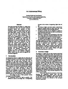
Figure 1. Procedures of an attack tracking on InterTrack ¶
³
v6-65002 v4-65001 10000 5 XXXX XXXX XXXX XXXX 1132613480159368 6TO4 XXXX XXXX XXXX XXXX v4-65001 v4-65002
v4-65002 v4-65001 10000 v4-65002 v6-65002 v4-65001 v6-65002 v4-65002
µ
´ Figure 2. ITM Trace Request / Reply
3
Overview of InterTrack
The main goal of InterTrack is to reconstruct the reverse AS path, which is the true attack path in AS hop level, and to detect the source ASes of an attack if possible. Another goal of InterTrack is to achieve the interconnection among traceback systems, detection systems and prevention systems inside an AS. The architecture of InterTrack refers to the Internet routing architecture, because the Internet routing architecture is designed along with the boundaries among operation domains, and such operation domains can have different operational policies. In a traceback trial, network operators cannot investigate other network domains; the same restriction is also observed in the BGP/OSPF routing operation. Therefore, they try to detect upstream neighbor ASes to ask them for further tracking. In InterTrack architecture, each AS has a set of InterTrack components. A set of InterTrack components includes: the Inter-domain Tracking Manager (ITM), Bor-
der Tracking Manager (BTM), Domain Traceback Manager (DTM), Decision Point (DP), and Traceback Client (TC). Figure 1 shows the overview of InterTrack architecture. A phased-tracking approach is applied on inter-domain traceback trials through InterTrack. InterTrack separates a traceback trial in four stages along with network boundaries; the tracking initiation stage, the border tracking stage, the intra-AS tracking stage and the inter-AS tracking stage. After accepting a traceback request on the tracking initiation stage, each AS preliminarily investigates its own status against the mounted attack on the border tracking stage. On the border tracking stage, an AS judges by InterTrack whether or not the AS is suffered from an attack, whether or not the AS is forwarding malicious attack packets, or whether or not the AS is suspected of having attacker nodes on the inside. Triggered by the investigated AS status, InterTrack runs the inter-AS tracking stage and the intra-AS tracking stage in parallel. Detailed behavior of each component were described in [11]. One of the key ideas of InterTrack is the modularization
of traceback systems. We analyzed the input values or key values of traceback systems [1–3, 6, 7]. In this paper, we do not mention the detail of our analysis because of the limit of pages. According to our analysis, the input values can be generated from a whole Ethernet frame in almost all traceback systems; thus, InterTrack achieves the interoperability among different traceback systems by delivering a whole Ethernet frame to ASes on the attack path through several requrest messages. Of course, the privacy issue of the packet payload comes into a question. One-way hash function is useful to conceal the confidential data on a packet, however, such concealing method limits available traceback techniques. On developping the prototype implementation of InterTrack, we decided to give the number of available traceback systems higher priority than confidentiality of a packet. Concealment of a traced packet on inter-domain traceback is out of scope in this paper because of the limited space. Each traceback system communicates with InterTrack through a BTM or a DTM. Both BTM and DTM are wrapper components to convert the packet information included in a traceback request to the input values for employed traceback systems. BTM and DTM also translate the results of traceback systems into the InterTrack message. BTM and DTM can be implemented as a module or a proxy to exchange the traceback information with the manager server of a specific traceback system.
4
Reverse AS Path Reconstruction
InterTrack reconstructs the reverse AS path of a DDoS attack through the border tracking stage and the inter-AS tracking stage. The border tracking stage on an AS reveals the AS status against the attack. If the border tracking stage judges that the AS received the attack traffic from some of upstream neighbor ASes, an ITM forwards an ITM trace request message to those upstream neighbor ASes which may forward the attack traffic. Here we explain the detail of AS status and the reconstruction of the reverse AS path on InterTrack.
4.1
AS status against a DDoS attack
An ITM decides actions by the AS status revealed on the border tracking. On the forwarding an ITM trace reply message, each ITM on the reverse AS path adds its AS status into the ITM trace reply message. The variations of AS status against a DDoS attack are shown in Fig. 3. On a traceback trial, an AS will have one of twelve variations of the AS status. Eight statuses can be expressed by the combination of following informations: directions of the forwarding path of an attack, the necessity of the detailed internal
(a)
(b)
AS
AS
[ Not Found ]
[ Attacker ]
(d)
(c)
To AS Z
AS From AS X
(e)
AS
[ Transit ]
(h) To AS Z To AS Z (IPv4 Global) Translator (IPv6)
NAT
To AS Y
AS From AS X
[ Victim ] (g)
(f) To AS Z
To AS Z
AS AS
AS
From AS X From My AS (IPv4 Private) [ Amplifier ] (i)
[ Infected ] (j)
From AS X (IPv4)
[ NAT Traversal ] (k)
[ Translator ] (l)
refused
?
busy
wait
AS
AS
AS
AS
[ Refused ]
[ Unknown ]
[ Busy ]
[ Wait ]
Figure 3. Variations of state of an AS on an attack
inspection, the notification of an address translation. In addition to these combinations, there are four error statues. First, we consider the relation with a neighbor AS. Basically, an AS status is composed of the status of the inside and each status on the point to point (P2P)link between each neighbor AS. The status on a P2P link can be described by the packet directions, that is, incoming and outgoing. If an AS find a packet or flow of the DDoS attack on the incoming direction in a P2P link, the P2P link is a Victim link, that is, the AS receives the DDoS attack flow from the neighbor AS. The status of a P2P link is Attack when the DDoS attack is detected on the outgoing direction on the P2P link. When the DDoS attack is not detected either on the incoming direction or the outgoing direction of an P2P link, the AS status on the P2P link is Negative. If the DDoS attack is found both on incoming and on outgoing direction of a P2P link, it indicates a Loop has occurred. Usually, Loop is an error state which indicates the error of the BTS or some wrong routing so that a more detailed investigation is required. Therefore, a Loop link is defined as equal to the Attack and Victim link. Next, we consider about the AS status with all relations between each neighbor AS. If all P2P links shows Negative, the AS status is judged as Not Found (Fig.3a). When each border tracking on each P2P link judges either Negative or Victim, an AS is in Victim state (Fig.3b). On the other hand, an AS has Attacker state when the results of P2P links either Attack or Negative (Fig.3c). An AS status is judged as Transit when the investigation results of P2P links contains Negative, Attack, and Victim (Fig.3d). Here we consider the AS status with the internal status of an AS. If there is a possibility that an attacker node is inside the AS, the AS is in Amplifier state (Fig.3e). The border tracking stage judges the AS status as an Amplifier state in the following cases: (I) the number of Attack links
is more than the number of Victim links, (II) the amount of traffic to some Attack link is increased remarkably, (III) one of P2P links shows Loop, (IV) when the AS connects to a neighbor AS with several links, one P2P link is attack and the other is Victim. When an AS is in the Amplifier state or in the Attacker state, the AS has to start the intra-AS tracking. If there is a need to start intra-AS tracking, a BTM adds an ASK DTM flag in the reply message to the ITM. A BTM also adds an ASK DTM flag when the border tracking stage shows the Infected state (Fig.3f). The Infected state indicates that the AS is attacked not from other ASes, but from the inside. Some attacks employ address translation techniques, such as IPv4/IPv6 tunneling or NAT [25]. If an attack comes from the IPv4 private segment which is operated by an AS, the border tracking judges the AS is in a NAT traversal state (Fig.3g). The border tracking stage indicates a Translator state when the attack comes through an 4to6 tunnel or 6to4 tunnel (Fig.3h). In these translation cases, a BTM adds the information of the translation. If an AS employs a logging technique such as SPIE [3] for the BTS, the BTS may store the previous packet information before the packet was translated. If BTS has the previous packet information, then the BTM also adds such previous packet information into the reply message. When an ITM receives the information of the translation from the BTM, the ITM adds the information into the ITM trace request message. Then, in order to start further traceback trials in different address space, the ITM changes the role to the ITM on another address space, or forwards ITM trace request message to another ITM on the same AS. Finally, we consider four error states on the border tracking. Each AS can refuse a traceback request along with its operational policy. If an AS refuses a traceback request, then, the ITM adds a Refused state as its AS status into the ITM trace reply message, and sends the ITM trace reply message to the issuer neighbor ITM (Fig.3i). If an ITM, a BTM, or a BTS is busy because of processing other traceback requests, the AS status becomes Busy (Fig.3j). When something wrong has occurred in the border tracking stage, The BTM replies with some error message. Then, the AS status is judged as Unknown, the ITM adds an error message from the BTM into the ITM trace reply message (Fig.3k). An ITM will reply Wait as the AS status if an AS is in the border tracking stage, but the AS needs much more time to get the result due to the limitation of the BTS (Fig.3l).
4.2
Loop Detection on Forwarding an ITM Trace Request Message
In order to avoid the loop in forwarding an ITM trace request message, the ITM on each adds its ITM ID into the ITM Path List field on the ITM trace request message when
the ITM forwards the ITM trace request message to neighbor ASes. Using the ITM path list and the message ID of an ITM trace request message, each ITM judges whether a loop on the message forwarding occurs or not. An ITM has ITM IDs which represent the address spaces covered by the ITM. The ITM ID on each address space is represented by the address space information and AS number. For example, each ITM ID of AS 2500 is v4-2500 in the IPv4 global network, v4-2500-private in the IPv4 private network, v6-2500 in the IPv6 network. The origin ITM, which originates an ITM trace request message, assigns a message ID to a traceback request on the tracking initiation stage. A message ID is composed of the ITM ID of the origin ITM and the sequence number assigned by the origin ITM. When a result of the border tracking contains a neighbor AS as the upstream neighbor and the ITM ID of the neighbor AS is already included in the ITM path list field, then, an ITM concludes a loop occurs and the ITM does not forward the ITM trace request to the neighbor ITM. An ITM also judges a loop when the receive ITM trace request message contains its own ITM ID in the ITM path list field. In this case, the ITM does not reply with the ITM trace reply message to the issuer neighbor ITM. The ITM path list field contains all ITM IDs which represent the partial reverse AS path of the attack. Each ITM ID indicates each traversal AS of the ITM trace request; therefore, an AS can refuse the traceback request when an untrusted AS is included in the ITM path list. In addition to the ITM path list field, an ITM trace request message contains Time-To-Live (TTL) field in order to stop an endless forwarding. Each ITM decrements the TTL value on forwarding an ITM trace request message. If the TTL value reaches zero or a negative value, an ITM stops forwarding the ITM trace request. According to the analysis by team Cymru [24] or by Geoff Huston [12], the observed maximum AS path length was less than 40 hops, and the weekly average AS hops is about 5 hops. Therefore, the maximum TTL is settled in 64 with some provisioning and the default TTL value is defined as 5.
4.3
Inconsistency among Tracking Results of each AS
An ITM trace reply message may contain some inconsistencies among each ITM result on the Reverse AS path. The inconsistency will occur in these cases as follows: When the ITM trace reply message reports Victim or Infected state on the result of other ITM, this inconsistency is caused by two kinds of mistakes. One case is that the BTM, whose AS is in several hops away from the origin ITM, mis-judged the AS status as Victim or Infected. The other inconsistency is that an ITM request message was generated and forwarded from
a transit AS and the ITM request message wrongly reached the true Victim AS by the mis-judges in several ASes. If the ITM trace reply message contains Not Found on the results of other ASes, an ITM made an incorrect forwarding to neighbors that are not in the real attack path, or the BTM of an AS mis-judged the AS state as Not Found. The ITM Subtree does not have the ITM ID of the former issuer on the outgoings field when the result of the border tracking on the deeper hop AS was wrong, or when the mis-forwarding continuously occurred in several hops. The ITM trace reply message may contain a loop in the ITM Subtrees field. If the same ITM ID is listed both on the Outgoings filed and the Incomings field of a ITM Subtree field, the ITM Subtree would indicate that the border tracking on the AS was wrong or the routing loop really occurred between two ASes. When a shallower hop ITM’s ID is contained in the Incomings field on the result by the deeper hop ITM, the BTM on the deeper hop AS mis-judged, or the wrong message forwarding continuously occurred from the shallower hop AS to the deeper hop AS. Even when an ITM trace reply message contains some inconsistency, the network operator on the original issuer AS can contact each AS by referring to the reverse AS path on the ITM trace reply message. On the other hand, each AS on the reverse AS path holds the partial ITM paths both on the received ITM trace request messages and on the ITM trace reply messages from neighbor ITMs. Hence, each AS can confirm the inconsistency on the reverse AS path by itself even when the AS is not the original issuer AS.
4.4
Analysis of Attack Cases against the InterTrack
Attack cases to the InterTrack architecture are considered here, and the feasibility of InterTrack against each attack case is then discussed, while the defending techniques to cover the vulnerabilities of InterTrack are explored. Against the Numerous requests from a TC, DP can limit or drop requests from TC in a unit time. In addition to this, DP’s authentication and rate-limit functions can be separated from ITM; therefore, the ITM network cannot be affected by the processing rate-limits on DP and can treat other requests while a TC attacks by numerous requests. An attacker may try to hijack a TCP connection between components. In InterTrack, each TCP session between two components is based on IPSec authentication [15]; therefore, each component will not accept the request of connection from an unauthorized node. Moreover, network operators can easily apply filter rules on the nearest routers for each component in the source address and the destination address pair, because the neighbor components of each component are fixed or limited. Furthermore, if an ITM has several interfaces, each connection to a neighbor com-
ponent can be achieved on a closed private network. By a combination of such techniques, network operators can protect InterTrack from SYN floods, or UDP floods, even when the attacker spoofs the source IP address of attack packets as the IP address of a component. Since each connection of two components can be constructed on the closed private network, such a private network is not affected by the bandwidth consumption on the main link of a neighbor AS. Even when the connection of two components is achieved as the on-line connection, priority queuing techniques can turn down the effect of the bandwidth consumption against the InterTrack messaging. Also, the ITM network is an overlay network. If other routing paths are prepared, the ITM network can tolerate the influence of link-downs or route flaps. If an ITM is hijacked by an attacker, it becomes a serious security issue over several ASes because the attacker can steal the inside information of the hijacked ITM’s AS and can attack by faked ITM trace request messages and spoofed ITM race reply messages. By hijacking other InterTrack components, an attacker can steal the inside information or can dirty traceback results. Therefore, each AS should protect the intrusion to the InterTrack as strongly as possible.
5
Preliminary Experiments with Implementation
We have developed a prototype implementation of InterTrack. We developed basic functions of InterTrack in C language on FreeBSD, except for the function which applies the AS’s operational policy and IPSec encryption. We employed LIBXML2 [10] for the XML parser of InterTrack messages like Fig. 2. We also developed a sample BTM and a sample DTM, both work as a proxy for PAFFI [13] which is an implementation of hash digest logging method by Yokogawa Electoric Corporation. The volume of the prototype code was approximately 50,000 lines in total. To evaluate the basic workloads of the ITM network, we had a preliminary experiment with the prototype implementation of InterTrack. For the experimental environment, we used 9 Dell Power Edge 1855 blade servers as a testbed network. Each blade server was equipped with Pentium III 1.4GHz CPU, 1024 MB RAM and two gigabit Ethernet interfaces. These 9 blade servers were divided into two blade cages and interconnected with each other through two layer 2 switches on each blade cage. In this experiment, we measured the overhead on the message processing of ITM. We regarded a blade server as an AS, we ran an ITM on each blade server with a dummy BTM function which judges all neighbor ITMs except the issuer one as upstream neighbors. On the Control Network, each ITM synchronized its own time to the NTP server and
Processing Time on Dummy BTM (msec.)
2000
RTT (msec.)
1500
1000
500
0 1
2
3
4
5
6
7
8
150
100
50
0 0
1
2
# of AS Hops
3
4
5
6
7
8
# of ITM
(a) RTT of ITM along with AS hops
(b) The processing time of Dummy BTM function
Figure 4. RTT of a ITM Traceback Request in a liner topology
Table 1. Response time of Software version PAFFI on VMware
Max (sec.) Min (sec.) Mean (sec.) Median (sec.) Var
Found case 3.27 0.58 1.57 1.58 0.04
Not Found case 3.99 0.19 1.61 1.59 0.10
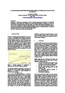
other ITM nodes. On the Experiment Network, each ITM connects to only neighbor ITMs in a liner topology according to the assumption that each AS employs a hash digest logging method [13,21]. We measured the relation between the RTT of ITM trace request messages on the origin issuer ITM and the number of hops forwarding the ITM trace request messages. With over-provisioning about the average length of AS hops [12, 24], we measured RTTs of the 1,000 ITM trace requests from 1hop to 8hops. Each trial ran independently with 5 seconds interval. The average RTT of ICMP on Experiment Network between each neighbor nodes was 0.197 milliseconds. Fig. 4(a) shows the box-whisker plot of the experiments. Including outliers, all messages returned to the original issuer ITM within 2 seconds, and most of them were less than 250 milliseconds. In the result of 8hops, the average processing time on dummy BTM of each ITM was less than 0.38 milliseconds. The processing time of the dummy BTM function was
shown in Fig. 4(b). In this evaluation, we couldn’t evaluate the RTT of an ITM trace request message with an actual implementation of hash digest logging method because of the limited resource of the testbed environment. As a sample data, we measured the response time of the software PAFFI [13] which was run on a VMware Workstation 5.0 [26]. The host computer of the VMware was Windows XP SP2 on Dell PowerEdge 1550 with Intel Pentium III 993 MHz processor and 1.5 GB RAM. On the performance evaluation of PAFFI, we allocated the VMware 768 MB memory for running paffi, and we prepared a test client VMware node on the same host computer. We measured this response time in 1,000 trials both on the case of Found and on the case of Not Found in the environment shown in Table 1 shows the results. According to the result of Fig. 4 and Table 1, we roughly estimate the RTT of an ITM trace request would be about 14 seconds in average where the AS path length was 9 and each AS used PAFFI as BTS. Along with this preliminary evaluation results, we conclude that the bottle neck point of the traceback through InterTrack would be BTS on each AS, however, a traceback would be finished in reasonable short time with hash digest logging techniques.
6
Related Work
Achieving interconnection architecture for the interdomain traceback is one of research topics on traceback techiniques. In this section, we compare InterTrack with other interconnection architectures for traceback systems. For comparison, we investigated the following architectures: eIP/iIP [19], RID [18], RID-MEW [14] and Inter-
Track. These traceback architectures divide the operation boundary along with network dormains. Each interconnection architecture delivers the packet information to other network domains by some messages for inter-domain traceback and interconnect different traceback systems for the internal inspection on each network domain through manager nodes. For the internal inspection, each interconnection architecture allows an AS to choose the traceback system according to pros and cons. eIP/iIP [19] and RID-MEW [14] have reported the expected time to finish a traceback trial. Although their experimental environments are different from each other, the average time spent on a traceback trial was less 40 seconds on eIP/iIP, RID-MEW and InterTrack. Even when the response time of PAFFI is considered, the average time of a traceback trial on InterTrack is comparable to others. Through these comparisons, InterTrack can be considered a competitive traceback architecture.
7
Conclusion
Developing an automated inter-domain traceback architecture has long been viewed as impractical due to the barriers on the operational boundaries and the dependence on specific tracking techniques. InterTrack’s key contribution is to achieve the inter-domain traceback in a practical way. Because of the phased-tracking apporach of InterTrack, each AS can control a traceback operation on its operation domain by itself, and can track back an attack on its operation domain with different traceback techniques regardless of traceback systems on other ASes. The federation of internal traceback trials on InterTrack enables ASes to cooperate with others on an inter-domain traceback trial automatically, while concealing the sensitive information of each AS. Through preliminary experiments, the time spent for an inter-domain traceback in 9 AS hop length was estimated to be 16 seconds in the case where each AS uses hash-digest-logging method. Through discussions and comparisons among other traceback architectures, we explained InterTrack as the competitive traceback architecture against attacks. In future work, in order to confirm the feasibility of InterTrack, more complex cases where ASes employ various traceback techniques such as specialized routing methods [7, 23], flow sampling methods [8, 20], hash-digestlogging methods [13, 21] etc., will be evaluated.
References [1] Arbor Networks. Peakflow SP. [2] Aruba Networks. Aruba Tech Briefs. [3] BBN Technologies. Source Path Isolation Engine (SPIE).
[4] A. Belenky and N. Ansari. On IP Traceback. IEEE Communications Magazine, 41(7):142–153, July 2003. [5] B. Carpenter and C. Jung. Transmission of IPv6 over IPv4 Domains without Explicit Tunnels. RFC 2529 (Proposed Standard), Mar. 1999. [6] Cisco Systems, Inc. Catalyst 6500 Series Command Reference, 8.2 - fotmat to ping - l2trace. [7] Cisco Systems Inc. Remotely triggered black hole filtering destination based and source based. Technical report, Cisco Systems Inc., Feb 2005. [8] B. Claise. Cisco Systems NetFlow Services Export Version 9. RFC 3954 (Informational), Oct. 2004. [9] A. Conta and S. Deering. Generic Packet Tunneling in IPv6 Specification. RFC 2473 (Proposed Standard), Dec. 1998. [10] Daniel Veillard. The XML C parser and toolkit of Gnome libxml. [11] H. Hazeyama, Y. Kadobayashi, M. Oe, and R. Kaizaki. Intertrack: A federation of ip traceback systems across borders of network operation domains. In Proceedings of ACSAC ’05, Tech. Blitz Session, Dec. 2005. [12] G. Huston. BGP Table Data. [13] Institute of Applied Internet Technology Inc. PAFFI: PAcket Footmark FInder. [14] T. Kai, A. Nagashima, H. Nakatani, NaohiroFukuda, S. Hiroshi, A. Hashiguchi, T. Suzuki, and KatsujiTsukamoto. Rid implementation report, Nov. 2004. Presentation on INCH Working Group session in 61th IETF meeting. [15] S. Kent and R. Atkinson. IP Encapsulating Security Payload (ESP). RFC 2406 (Proposed Standard), Nov. 1998. [16] D. McPherson and C. Labovitz. WorldWide ISP Security Report, Sep. 2005. [17] J. Mirkovic and P. Reiher. A Taxonomy of DDoS Attack and DDoS Defense Mechanisms. ACM Computer Communications Review, 34(2):39–54, Apr. 2004. [18] K. M. Moriarty. Incident Handling: Real-time Inter-network Defense. IETF, Internet Draft, draft-ietf-inch-rid-05.txt, Nov. 2005. [19] M. Oe, Y. Kadobayashi, and S. Yamaguchi. An implementation of a hierarchical IP traceback architecture. In Proceedings of IPv6 Workshop, SAINT 2003, Orland, USA, Jan. 2003. [20] P. Phaal, S. Panchen, and N. McKee. InMon Corporation’s sFlow: A Method for Monitoring Traffic in Switched and Routed Networks. RFC 3176 (Informational), Sept. 2001. [21] A. C. Snoren, C. Partridge, L. A. Sanches, C. E. Jones, F. Tchakountio, S. T. Kent, and W. T. Stayer. Single-packet IP traceback. ACM Transactions on Networking, 10(6):119– 137, Dec. 2002. [22] P. Srisuresh and K. Egevang. Traditional IP Network Address Translator (Traditional NAT). RFC 3022 (Informational), Jan. 2001. [23] R. Stone. CenterTrack: an IP overlay network for tracking DoS floods. In Proceedings of 9th USENIX Security Symposium ’00, Denver, USA, Aug. 2000. [24] The Team Cymru. The team cymru BGP data page. [25] US-Cert. Malware tunneling in ipv6. Technical report, USCert, May 2005. [26] VMware Inc. Vmware workstation.