... consisting of a large un- committed array of programmable logic and intercon- ... has the manual and automatic methods to sample and pro- cess the data, and ...
IEEE TRANS. ON INSTRUM. MEAS.
1
An Effective Framework to Evaluate Dynamic Partial Reconfiguration in FPGA Systems Kyprianos Papadimitriou, Student Member, IEEE, Antonis Anyfantis, and Apostolos Dollas, Senior Member, IEEE Abstract—The most popular representative devices of reconfigurable computing are the Field Programmable Gate Arrays (FPGAs). A promising feature of an FPGA is the ability to reuse the same hardware for different tasks at different phases of an application execution. Moreover, the tasks can be swapped on the fly while part of the hardware continues to operate. This is known as dynamic reconfiguration and evaluation of its performance presents interesting research challenges. This paper introduces a general framework to measure the reconfiguration time from the system perspective. In addition, a methodology to setup different system parameters, gather and process automatically the experimental results has been developed. It is proven that these parameters affect applications designed in a dynamically reconfigurable system, and rapid evaluation enables the quick examination of their impact on performance. Results demonstrate the usefulness of the framework. Index Terms—Dynamic reconfiguration, Partial reconfiguration, Field programmable gate arrays, Reconfigurable architectures, System analysis and design, Measurement
I. Introduction
F
PGAS are integrated circuits consisting of a large uncommitted array of programmable logic and interconnect that can be configured to implement digital circuits. Most FPGAs are SRAM-based, meaning that SRAM bits are connected to the configuration points in the chip, and programming the SRAM bits configures the chip. FPGAs can be customized for the application at hand, and exhibit performance increase over software solutions while retaining flexibility. Different application domains have benefited from their implementation on FPGAs ranging from bioinformatics on high-end systems [1] to motion detection on low-cost systems [2]. One of the most interesting features of some FPGAs is run-time or dynamic reconfiguration [3], and recent research demonstrates that there is a great deal of interest in it [4], [5]. This capability allows to replace a module located on a part of the device while the rest remains intact continuing its operation. Multiple design modules can time-share the physical resources, and the hardware can adapt to the application at hand, or even to a segment of an application. This way smaller devices can be used enabling reduction in cost, size, power, and more efficient use of the board space. Numerous applications have benefited from their implementation in a dynamic manner. In the network domain, Kachris et al. [6] proposed a dynamically reconfigurable The authors are with the Department of Electronic and Computer Engineering, Technical University of Crete, Chania, 73100, Greece, Phone: (+3)-02821-037219, email: {kpapadim, aanyfantis, dollas}@mhl.tuc.gr
processor to meet the requirements of the network workload. Modules like encryption, compression and intrusion detection found in contemporary edge routers, are dynamically loaded according to the traffic distribution to serve the different network flows. In the field of Software Defined Radio, a prototyping kit was released to the market, which uses partial reconfiguration to support different communication waveforms and protocols within a single device [4]; this allows for flexible and efficient communication between equipment that differs in vendor, RF frequency or interface protocol. Also, dynamic reconfiguration has been used to support high energy physics research at CERN’s Large Hadron Collider [5]. These are some of the systems that establish dynamic reconfiguration as a feasible way to design commercial applications. However, it can degrade the execution time due to the time required to download the configuration data before the system is ready to execute. This is known as reconfiguration overhead and quantitative analysis is needed to examine whether dynamic reconfiguration is justified for an application. Also, this analysis can be used to evaluate mechanisms proposed to reduce reconfiguration overhead such as configuration caching, compression, and prefetching [7], [8]. In [9] we published initial results on a methodology to evaluate dynamic reconfiguration. The shortcomings of that work showed that the process was tedious due to the time needed to prepare each experiment and the amount of data that had to be sampled and processed. The main contributions of the present paper are: • • • •
a methodology to evaluate dynamic reconfiguration of FPGAs from a system perspective, a framework to quickly setup the system parameters, sample and process the experimental data, definition of the time components that add up to the reconfiguration overhead, and results showing the variation of reconfiguration time over different values of system parameters.
The paper is structured as follows: Section II has the background on FPGAs and reconfiguration, along with related work on performance evaluation. Section III discusses the system and the methodology. Section IV presents the piece-wise delays that add up to the reconfiguration time and the way they were measured. Section V has the manual and automatic methods to sample and process the data, and their quantitative comparison. Section VI has the experimental results, and Section VII concludes the paper.
2
IEEE TRANS. ON INSTRUM. MEAS.
OPB
PLB
in two frames, the data frame plus a pad frame. The configuration data produced for programming the FPGA is called bitstream. When only a portion of the FPGA is to be configured, i.e. a number of frames, a partial bitstream is produced. In order to create the partially reconfigurable modules we followed the differencebased flow [12], [13] by making small changes to a design and then generating the bitstreams based on the differences between the designs. Transition to the module-based flow [14] does not require any modification in the proposed framework. The same design flow applies as well to the latest Xilinx high-end FPGAs, i.e. Virtex-4 and Virtex-5, except that the configuration granularity is smaller. B. Evaluation of Reconfiguration
Fig. 1. The Virtex II-Pro FPGA resources and configuration frames.
II. Background This section discusses the Xilinx Virtex-II Pro FPGAs [10] and the reconfiguration mechanism. Although we experimented with the specific device, our system is rather general and can be used for other FPGA platforms. A. The Virtex-II Pro FPGA and Reconfiguration The generic structure of the Virtex-II Pro FPGA is shown in Figure 1. It comprises the hardcore processor PowerPC, and the high-bandwidth Processor Local Bus (PLB) and the slower On-Chip Peripheral Bus (OPB) [11] for the communication with the array. The modules implemented in the array logic act as peripherals of the processor. The array is 2-D fine-grain heterogeneous, mainly composed of configurable logic blocks (CLBs), hardcore memory blocks (BRAMs) and hardcore multipliers. Each CLB contains look up tables (LUTs), flip-flops, multiplexers and gates that are configured to implement the design logic. The array can be configured by the processor with dedicated instructions through the Internal Configuration Access Port (ICAP), an 8-bit built-in interface that configures the FPGA at a maximum rate of 66 MHz. A BRAM attached to the ICAP caches configuration bits prior loading to the FPGA configuration memory. The configuration memory of the Virtex-II Pro is arranged in vertical frames that are one bit wide and stretch from the top edge to the bottom of the device. Frames are the smallest addressable segments of the device’s configuration memory space, so, all operations must act on whole configuration frames. They do not directly map to any single piece of hardware; rather, they configure a narrow vertical slice of many physical resources [10]. A pad frame is required to be added at the end of the configuration data which flushes out the reconfiguration pipeline in order for the last valid frame to be loaded. Therefore, to write even one frame to the device it is necessary to clock
McGregor and Lysaght evaluated a self-controlling dynamically reconfigurable system using a logic analyzer, and reported that the reconfiguration process was significantly slower than the execution speed of the FPGA logic [15]. In [16], McKay and Singh developed tools and techniques for debugging a dynamically reconfigurable system. A logic analyzer was used to evaluate the improvement of specialized circuits such as constant coefficient multipliers over the corresponding general circuits. Tan et al. [17] compared the performance between two interfaces used for partial reconfiguration of FPGAs to evaluate the tradeoffs between design complexity, area overhead, reconfiguration flexibility and reconfiguration latency. They used the Xilinx Chipscope Pro tool that operates as an internal logic analyzer [18]. In [19], Hymel et al. studied the performance impact on timing and resource utilization of the Xilinx’s new partial reconfiguration design flow when targeting Virtex-4 FPGAs through remote updating. The above works demonstrate that performance evaluation of dynamic reconfiguration is an interesting area. Also, as the existing tools do not support simulation of dynamic reconfiguration due to the lack of behavioral and hardware models, the above works employed a logic analyzer, either for measuring reconfiguration time for a few bits, or, evaluating specialized circuits over the general counterparts, or, evaluating partial reconfiguration interfaces. However, none of them had reported a method to gather experimental results automatically, nor examined the overhead incurred by the components that participate in the reconfiguration process. Thus the development of a general infrastructure for elaborating dynamic reconfiguration seems promising. Our framework is the first to evaluate the overhead added by the physical components that participate in the reconfiguration process. In [9] we defined some piecewise delays during reconfiguration and introduced measurements with a logic analyzer, but we included results taken with software methods only. The present work discusses logic analyzer measurements along with the automatic method. According to a publication by Xilinx researchers, once data are available in the configuration cache, the time to reconfigure a single frame in a Virtex-II Pro FPGA using the ICAP at 66 MHz is in the order of
Papadimitriou and Anyfantis and Dollas: AN EFFECTIVE FRAMEWORK TO EVALUATE DPR IN FPGA SYSTEMS
Compact Flash contains : Start up bitstream Partial bitstreams
System Ace Controler
4 DIP Switches
Virtex-II Pro FPGA
3
XUPV2P Platform
Push Buttons
4 LEDs
UART
Expansion Headers
9-bit LED shift register 10-bit LED up/down counter FPGA internal signals
Within the automatic framework, the captured data are stored and then transferred to the PC for post processing
Fig. 3. The shadowed boxes represent the internal components of the FPGA. The white boxes are parts of the platform connected externally with the FPGA.
Fig. 2. Block diagram of the experimental setup.
decades of µs [20]. A more recent work reveals the reconfiguration time of many frames for Virtex-II and Virtex-4 FPGAs, again after the configuration data are available in the configuration cache [14]. We measured and verified this time with software methods in [9]. In a later Section of the present work we measure this time using a logic analyzer also, and show that it conforms with the Xilinx published value and our software measurement. However, this time is not the only aspect in the reconfiguration process, and other physical components of the system add significant delays, causing reconfiguration time to increase more than three orders of magnitude as compared to the above time. Moreover, although the reconfiguration time over the number of frames is linear [14], we prove that this does not hold always at platform-level. III. Experimental Setup The setup for the experiments shown in Figure 2, consists of a XUPV2P platform with a Virtex-II Pro FPGA [21], a board with LEDs, an Agilent 1680A logic analyzer, and a PC. The platform is connected through the serial port to the PC for evaluation, and through the on-board expansion headers to the LED board and to the logic analyzer for monitoring internal FPGA signals. This setup allows for the measurement of the time components that add up to the total reconfiguration latency. Just as the total latency of a dynamic memory is substantially higher than its access time, the total reconfiguration latency is substantially higher than the execution time. Hence, we need to define and then measure the constituent latencies, which will allow to efficiently exploit reconfigurability in the development of an application. A. The XUPV2P Platform Figure 2 shows the platform parts we use in our system. A non-volatile compact flash memory holds the configuration bitstreams, i.e. the initial and the partial bitstreams.
The System ACE Controller supervises the transfer of data from the compact flash to the FPGA. In the FPGA, the PowerPC and several peripherals have been configured. A push button allows the user to trigger a reconfiguration at any time during operation. Four DIP switches control the functionality of an FPGA peripheral. The UART sends status messages and debugging information to the PC. The LED board is connected to the expansion headers for displaying the peripherals’ operation and monitoring some FPGA signals with the logic analyzer. B. The FPGA System The FPGA internal system is shown in Figure 3. The PLB and OPB buses communicate through a bridge. The PowerPC controls the reconfiguration process. A cyclic shift register peripheral has been implemented as static logic; a logic function controlling an up/down counter and ten dummy logic peripherals have been designed as partially reconfigurable modules. This way, dynamic reconfiguration is demonstrated as the cyclic shift register continues its operation while a part of the array is being reconfigured. The push button forces the PowerPC to request a partial bitstream from the compact flash, then write it in the PowerPC memory, and subsequently transmit it to the HWICAP module1 . The bitstream is not written to the PowerPC memory with one transaction only. A specific amount of bits, the so called data chunk, is first written from the compact flash to the PowerPC memory. The size of the data chunk depends on a system parameter called buffer cache (bc), which affects the amount of bits transferred with one transaction. More specifically the bc size defines the amount of memory for buffering reads and write calls to the System ACE Controller. The size of the processor memory allocated for the data chunks, called processor 1 The HWICAP module is provided as a ready-to-use IP core, and allows for the embedded processor to control the Internal Configuration Access Port (ICAP) for reading and writing the FPGA configuration memory at run time.
4
array (pa), affects the amount of configuration data stored before writing to the HWICAP takes place. Then, the configuration data are written to the BRAM of the HWICAP - called configuration cache - and when it is full the bits are written into the FPGA configuration memory via the ICAP; the writing through the ICAP is controlled with software instructions. The above process is repeated until the entire bitstream is loaded. Hence, iterations of the operations: (i) Compact Flash to PowerPC memory, (ii) PowerPC memory to HWICAP configuration cache, and (iii) HWICAP configuration cache to FPGA configuration memory occur until the entire bitstream is written to the FPGA configuration memory. Two more peripherals have been implemented for evaluation purposes; the reconfig status peripheral which outputs a signal indicating the duration of reconfiguration process, and the UART peripheral which transmits status messages to the PC. C. Creating the Partial Bitstreams In order to create the partial bitstreams we followed the difference-based design flow [12], [13]. We implemented a logic function that controls a simple up/down counter as a partially reconfigurable module by affecting the LUTs on the same column. Also, we implemented 10 dummy peripherals of different sizes as partially reconfigurable modules by changing the values in the LUTs of contiguous columns, starting from the left and moving to the right side of the chip. Thus 11 peripherals were initially created, one having the logic function that controls the up/down counter only, and the other ones having the logic function plus 1 dummy peripheral. This resulted in 11 modules each having a different size. Then, for each module a second configuration was created, with equivalent size but different functionality. This resulted in an overall of 22 partially reconfigurable modules that were stored as partial bitstreams in the compact flash. The two smallest partial bitstreams reconfigure the logic function only, the next two larger partial bitstreams reconfigure the logic function plus the smallest dummy peripheral, and so on. Table III of Section VI has the sizes of the experimental partial bitstreams as produced with the Xilinx tools. In the next sections we measure the time needed by the system to reconfigure the FPGA with partial bitstreams ranging from 20,352 to 119,872 bits. It is clear that advantages of dynamic reconfiguration do not come without cost as the bitstreams must be stored elsewhere in the system. The most obvious tradeoff is between external nonvolatile memory and FPGA size. In terms of silicon area and hence cost, it is preferred to store inactive designs in cheaper non-volatile memory [22]. Alternatively, internal BRAMs can be used to store partial bitstreams [20] but this poses limitations to the size of the bitstreams that can be stored. Although we do not abandon such a scenario, in present work we consider applications where the configuration data are stored in an external low-cost memory.
IEEE TRANS. ON INSTRUM. MEAS.
D. Demonstration of Dynamic Reconfiguration The cyclic shift register is static, and its output was monitored with the LED board. The up/down counter counts upwards or downwards and its output was monitored with the LED board as well. Its operation depends on the boolean logic function. The latter’s output was monitored with 4 small LEDs located on the XUPV2P platform. Two different boolean logic functions were created such as to be partially reconfigured, the bitwise “OR” and “AND” between four 1-bit operands. The operands’ values are given directly from the four DIP switches. The output of the logic function determines the counter’s behavior. During operation, when the reconfiguration button is pressed a partial bitstream is loaded. Depending on the experiment, the logic function that equals 20,352 bits up to the logic function plus the largest dummy peripheral that equal 119,872 bits are configured. The control of the counter - the logic function - changes on the fly, while the shift register continues its operation. This scenario is a simplistic one but it meets our needs as we are mainly concerned on reconfiguring the chip with bitstreams of different sizes. Real experiments for the different bitstreams of Table III demonstrate the usefulness of our framework. E. System Parameters Some parameters were configured as fixed values and others were varied during experimentation. The PowerPC main memory was 48 Kbytes and the stack was 6,000 bytes. The buffer cache (bc) of the processor was varied between 512 and 4,096 bytes. Its size defines the amount of memory for buffering reads and write calls to the System ACE controller. We also varied the size of the processor array (pa), i.e. the array allocated in the processor memory to store the configuration data chunks2 that were read from the compact flash. The HWICAP cache is implemented with one BRAM and equals 2,048 bytes. Interrupts of the processor were not enabled as our aim was to configure a system with low resources. F. System Operation Flow Figure 4 has the operation flow of the system. In step 1, at power-up the FPGA is configured, execution of user application starts and the PowerPC starts operation. In steps 2-3, the PowerPC does polling on the push buttons waiting for a reconfiguration to occur. In steps 4-5, the PowerPC writes configuration data from the compact flash to its memory. In step 6, the data are written word-byword to the configuration cache of the HWICAP. In step 7 the HWICAP BRAM is checked to determine if it has been fully loaded. If the HWICAP BRAM is full, then reconfiguration is performed in step 10 and all data contained in the HWICAP BRAM are written to the FPGA. Step 11 checks if reconfiguration of the FPGA has been completed. 2 Transactions were conducted in multiples of one sector per processor request using a software-routine. A sector is the smallest unit the compact flash is organized in and equals 512 bytes. Thus the processor array size was varied in multiples of a sector size.
Papadimitriou and Anyfantis and Dollas: AN EFFECTIVE FRAMEWORK TO EVALUATE DPR IN FPGA SYSTEMS
(1)
(2)
FPGA is programmed with initial configuration and starts execution
(4)
PPC samples push button
(5)
Transfer to PPC memory is completed
(6)
PPC writes a word to HWICAP BRAM
Has button firing reconfiguration been pressed?
(3) No
Yes
PPC requests a configuration data chunk from CF
(7)
Is HWICAP BRAM full?
Yes
No (8) (10)
Have all configuration data been sent?
FPGA reconfiguration Yes
No (11)
Has FPGA reconfiguration been completed?
No (9)
Yes (12)
FPGA executes new configuration
Other configuration data in PPC memory?
Yes
No Flush reconfiguration (13) pipeline
(14)
PPC detects reconfiguration completion
Fig. 4. System operation flow.
10
4 Rec-HWICAP = 51.917 ms
12
13
14
HWICAP-CM = 49.980 ms
RT = 101.323 ms
Fig. 5. Timing mode trace of the logic analyzer for one reconfiguration of bitstream 11 of Table III. The parameters used are buffer cache=4,096 bytes and processor array=4,096 bytes.
Execution of the new configuration starts in step 12 and the pipeline is flushed in step 13 if the reconfiguration was verified as complete in step 11; if it is not complete, then new configuration data will be loaded in step 9. In step 14, the PowerPC detects reconfiguration completion. Back to step 7, if the HWICAP BRAM is not full, in step 8 it is checked if all configuration data have been sent. If this is false, new configuration data are loaded from the compact flash or the PowerPc memory in step 9. If it is true, FPGA reconfiguration is performed in step 10. IV. Reconfiguration Time Breakdown and Measurement Methodology In order to gain complete understanding of the reconfiguration time, we define the delays that add up to it: • CF-PPC is the time to copy configuration data from the compact flash (CF) to the processor memory with one transaction. • PPC-HWICAP is the time to write configuration data
5
from the PPC memory to the HWICAP BRAM3 . • HWICAP BRAM-CM is the time to load the configuration data from one HWICAP BRAM to the FPGA configuration memory (CM). • Rec-HWICAP is the time elapsed between PPC detection that a reconfiguration has been fired and first launch of the configuration data from the HWICAP BRAM to the FPGA configuration memory. • HWICAP-CM is the time for loading all configuration data from the HWICAP BRAM to the FPGA configuration memory including the pad frame4 . • RT is the time elapsed between PPC detection that a reconfiguration has been fired and switching to the new execution; this is the total reconfiguration time. The first three delays were measured with software timers to evaluate the corresponding processor instructions in [9]. It was shown that, i) when the partial bitstream is smaller than the processor array (pa), it is written with one processor request only and stored in the processor memory in its entirety prior transmission to the HWICAP, ii) from the HWICAP side, configuration cache is 2,048 bytes and can not be changed, thus inhibiting writing and accommodation of the entire bitstream at once (even the bitstream 1 of Table III requires 20,352 bits = 2,544 bytes to be configured which can not be accommodated at once by the HWICAP BRAM), and iii) HWICAP is not the bottleneck. Moreover, in that work we measured the time to write the data in the configuration memory after they filled the configuration cache. This was made by measuring the HWICAP BRAM-CM delay which reflects the time to configure one frame, and it was found equal to 25.26µs which matches the Xilinx published values [20], [14]. The remaining three delays of the above list are measured in present work with the following signals captured with the logic analyzer: • ICAP signals (symbol ’ denotes active-low signal). – CE’ (input): The ICAP chip enable. – WRITE’ (input): Indicates writing to the FPGA configuration memory. It is deactivated during read. – BUSY’ (output): Indicates that ICAP is busy, either during write or read. • REC active: It indicates reconfiguration is in progress. It is set high when the PowerPC is notified that reconfiguration has been fired, and low when it is notified that reconfiguration has finished. This signal is exported from the reconfig status peripheral. • LF indicator: It marks the moment the FPGA starts execution of a new configuration. This signal is exported from the up/down counter peripheral to indicate that the logic function has been changed. 3 Due to the HWICAP BRAM size, the maximum data size per transmission equals the size of one BRAM, i.e. 2,048 bytes. 4 Note that this delay differs from the HWICAP BRAM-CM delay. The latter corresponds to the time needed to release the data that have filled one HWICAP BRAM. Contrarily, the HWICAP-CM is the time elapsed between the first configuration data start being written to the configuration memory and the last configuration data have been written to the configuration memory. Figure 5 helps to clarify this.
6
IEEE TRANS. ON INSTRUM. MEAS.
The delays were measured by the intervals between the edges of these signals, as shown in the example of Figure 5. This Figure shows a logic analyzer trace during reconfiguration of the largest bitstream of Table III. The numbers in the circles correspond to the numbers of steps of Figure 4. First, the REC active signal is asserted indicating that a reconfiguration has been requested. Activation of the CE’ signal indicates loading of configuration data from the HWICAP to the FPGA. Transition of the LF indicator signal, either from “0” to “1” or from “1” to “0”, marks the moment the FPGA switches to the new execution. Completion of the HWICAP’s BRAM write to the configuration memory is shown with the last rising edge of the CE’ signal. Finally, deactivation of the REC active signal indicates that the PowerPC has detected reconfiguration completion. Also, we measured the time the CE’ signal is active during one write transaction from the HWICAP configuration cache to the configuration memory, and we found it equal to 24.5µs, which matches the time to write one frame as published by Xilinx [14], [20], and our software measurements [9]. V. Experimentation Phase The experimentation phase consists of the stages from the setting of parameters to the data plotting. In the first subsection we specify the parameters we changed and the stages of experimentation. Then we discuss the manual experimentation method, which was used in a previous publication [9] but neither the method nor the results were discussed there. The third subsection has the automatic method. A. Parameters and Stages We examined the effect of the parameters introduced in Section III: • Partial bitstream size. We experimented with 11 different sizes varying from 20,352 to 119,872 bits. • Buffer cache (bc) size. It is varied from 512 to 4,096 bytes with a step size of 512, resulting in 8 different experiments. • Processor array (pa) size. It is varied from 1 to 8 sectors with a step size of 1, i.e. 512 to 4,096 bytes, resulting in 8 different experiments. The total number of experiments is given by all parameter combinations, found by multiplying the number (#) of different values of the parameters: #experiments = (#bitstreams) × (#pa sizes) × (#bc sizes) = 11 × 8 × 8 = 704
(1)
Initially the values of the parameters are set, the code is compiled and downloaded, and a self-test routine runs. Next, the logic analyzer is prepared to be triggered, the user pushes the button to fire reconfiguration and the logic analyzer captures the data. Then the delays are measured and sorted in a proper format in order to be plotted. The
TABLE I Time duration per user, or system, or combined user/system action, for one experiment with the manual method. action parameter change compilation,downloading self-test sampling measurement,sorting total time (for 1 exp.)
bitstream 15 s 12 s 16 s 30 s 60 s 133 s
pa size 15 s 12 s 16 s 30 s 60 s 133 s
bc size 25 s 45 s 16 s 30 s 60 s 176 s
definition of these stages is rather general and in the remaining section we discuss the manual method and the transition to the automatic method. B. The Manual Method It consists of the following stages: 1. Change of the parameters: The partial bitstream filename, the processor array (pa) size and the buffer cache (bc) size are changed separately for each experiment. 2. Compilation & downloading: In order for the changes to be applied on the partial bitstream filename and the processor array size, only the user code (C program) should be re-compiled as these two parameters are set in the user code. The buffer cache is part of the PowerPC settings and in order to be altered the entire project should be rebuilt, which incurs a long compilation. After downloading, a self-test routine is executed. 3. Sampling: The user prepares the logic analyzer for triggering, (s)he fires reconfiguration, and stops logic analyzer data capturing. 4. Measurement: The logic analyzer markers measure the intervals between the signal transitions. Each marker is programmed to be automatically positioned on the edge of the signal that is used to measure a delay. 5. Sorting: The user inserts the values into spreadsheet cells and sorts them according to the analysis (s)he wants to conduct. 6. Plotting of the spreadsheet values. The user has to carry out 704 iterations of stages 1 to 5 before the data plotting. Table I has the lower bounds of the time duration of each action5 . The overall experimentation time equals the total number of experiments multiplied with their respective duration, as shown in equation 2. In this equation we reduced the times we modify the buffer cache (bc) size, which according to Table I is the most time-consuming process, in order to provide the optimal sequence of experiments with respect to time: 5 Actions are distinguished in those carried out only by the user, e.g. parameter change, only by the system, e.g. self-test, or those that employ both, e.g. sampling. Actions are the same for other FPGA platforms and only the time duration of the system actions would be different.
Papadimitriou and Anyfantis and Dollas: AN EFFECTIVE FRAMEWORK TO EVALUATE DPR IN FPGA SYSTEMS
7
overall time = [(#experiments − #bc sizes) × (f ast total time)] +(#bc sizes × slow total time) = [(704 − 8) × (133s)] + (8 × 176s) = 93, 976s = 26.1h
(2)
In this equation the fast total time corresponds to the time to complete one experiment when any parameter except the buffer cache size is modified; the slow total time corresponds to the time to complete one experiment when the buffer cache size is modified. In addition, to reduce the overall time we exploit overlapping of the actions, i.e. distinct actions that do not require the same resources of the setup, so they can be conducted simultaneously. Two of the authors participated in the experimentation phase and observed which actions were overlapped. For example, preparation of the parameters for the next experiment (15 sec or 25 sec) can be simultaneously carried out with the sampling of the current experiment (30 sec). Specifically, while the one user prepares the logic analyzer, fires reconfiguration, and stops the capturing, the other user changes the parameter(s) for the next experiment. Also, compilation, downloading (12 sec) and self-test (16 sec) of the next experiment can be carried out while the user measures and sorts the current captured data (60 sec). Hence, in the previous equation we can eliminate the time duration of the actions that overlap with the longer ones of Table I: overall time w/ overlap = (#experiments) × [sampling time +(measurement, sorting time)] = (704) × (30s + 60s) = 63, 360s = 17.6h
(3)
Although the above time durations are optimistic, repetitions of the user actions were boring and we automated the process. C. The Framework Firstly, in order to reduce the compilations and downloads per experiment, we automated the change of the parameters which correspond to the 1st and 2nd stages of the manual method. Specifically, all combinations of bitstream sizes, and processor array sizes are now included in the processor code, and their values are changed at run-time within loop structures resulting in 11*8=88 experiments per one compilation and download. Regarding the buffer cache size change, recompilation is inevitable as its value is entered during the setup of the PowerPC - and not within the C code -, so, 8 compilations and downloads are required. After a buffer cache change, the 88 experiments can be conducted with a single run. Then we automated the data sampling, which corresponds to the 3rd stage of the manual method. This allows to exploit the full logic analyzer memory and relieves the user from triggering and stopping the logic analyzer. However, due to the latter’s memory limitations, the automatic run of 88 parameter combinations does not fit (8 combinations do not fit), and hence another sampling should be triggered.
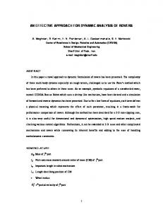
Fig. 6. Logic analyzer trace for successive reconfigurations of bitstreams 1 to 11 of Table III and processor array sizes ranging from 512 to 4,096 bytes.
The measurement and sorting that correspond to the 4th and 5th stages of the manual method were also automated. The captured data of each run are written to a .csv file and then transferred to the PC. A C program operates on windows of continuous data for identifying the edges of the signals where the measurements are to be taken, by searching for “01” and “10” patterns. Within a window, subtractions between the time values of the appropriate signal transitions are made, and the results are written in a new .csv file. Recapitulating, the framework consists of the following stages: 1. Change of the buffer cache size only. 2. Compilation & downloading: Combinations of all bitstreams and processor array sizes are compiled and downloaded at once, and then a self-test routine is executed. 3. Sampling: The logic analyzer is prepared for triggering and the reconfiguration button is pushed. Successive reconfigurations for all combinations of bitstreams and processor array sizes are performed. Once the logic analyzer memory is filled, capturing stops. 4. Export to .csv: Captured data are written to a .csv file. 5. Measurement & sorting: The .csv file is loaded to the C program for measurements and calculations. The results are sorted and written in a new .csv file, which is then imported into a spreadsheet. 6. Plotting. Stages 1 to 5 are repeated for all the buffer cache sizes resulting in 8 recompilations/downloads. In addition, 8 iterations should be executed due to the inadequacy of the specific logic analyzer memory. Table II has the time duration of each action. The overall time for the experiments is the number of the user interventions multiplied with the time to complete one run, and it is shown in equation 4. A user intervention is either a recompilation due to the
8
IEEE TRANS. ON INSTRUM. MEAS.
action parameter change compilation,downloading self-test sampling export to .csv measurement,sorting total time (for 88 exp.)
buffer cache 25 s 45 s 16 s 60 s 35 s 40 s 221 s
Rec-HWICAP
120
HWICAP-CM
RT
bc=3072, pa=4096
100 80 time (ms)
TABLE II Time duration per user, or system, or combined user/system action for one run using the framework. 88 different experiments, each one corresponding to a different parameter combination, are executed with a single run.
60 40
inadequate mem. 15 s 12 s 16 s 15 s 25 s 40 s 123 s
20 0 1
(a)
2
3
4
5
6
7
8
9
10
11
bitstream
120
Rec-HWICAP
HWICAP-CM
RT
bc=4096, pa=4096
100
change of the buffer cache size, or, a new sampling due to the inadequate logic analyzer memory.
time (ms)
80 60 40 20
overall time = (#experiments × buf f er cache) 0
+(#experiments × inadequate mem) = (8 × 221s) + (8 × 123s) = 2, 752s = 0.77h
(4)
The framework offers an improved productivity of 17.6h ÷ 0.77h = 22.8 times as compared to the manual method. Figure 6 shows a logic analyzer trace, captured with one triggering within the framework. Successive reconfigurations of all bitstreams for different processor array sizes result in 80 combinations that are then processed in an automatic way. With the manual method shown in Figure 5 only one reconfiguration for a parameter combination can be sampled. VI. Results We conducted experiments for all parameter combinations. In each graph of Figure 7 the bitstream size varies while the buffer cache size and the processor array size are kept constant. The three delays defined in Section IV were measured with the logic analyzer within the framework. For most parameter combinations the behavior of the delays resembles Figure 7 (a). It reflects the frequent case according to which the delay increases linearly with respect to the bitstream size. Figure 7 (b) shows the less frequent case wherein reconfiguration time for the bitstreams 3 and 4 decreases as opposed to the bitstream size. Thus the buffer cache of 4,096 bytes affects the time to write the configuration data. The Rec-HWICAP time is reduced which causes reduction to the RT time. This is due to the specific buffer cache size only, and does not depend on the processor array size. It is clear that increase in memory means is utilized more efficiently when reconfiguring the bitstreams 3 and 4. Table III has the total reconfiguration times for both cases of Figure 7. An interesting result derives from the comparison between the Rec-HWICAP delays of the two graphs for the same bitstream size. When buffer cache=4,096, for the bitstreams 1,3 and 4, the delay is significantly lower as
(b)
1
2
3
4
5
6
7
8
9
10
11
bitstream
Fig. 7. Reconfiguration time and piece-wise delays for different bitstreams and buffer caches (bc), and fixed processor array (pa). TABLE III Size of the experimental partial bitstreams and reconfiguration times for the parameters of Figure 7. bitstream 1 2 3 4 5 6 7 8 9 10 11
#words 636 842 1,258 1,464 1,880 2,086 2,502 2,708 3,124 3,330 3,746
#bits 20,352 26,944 40,256 46,848 60,160 66,752 80,064 86,656 99,968 106,560 119,872
RT(a) (ms) 29.7 37.2 43.7 48.3 56.1 66.7 73.1 79.2 88.6 94.5 101.1
RT(b) (ms) 20.2 37.2 32.8 37.4 56.2 66.8 73.2 79.3 88.8 94.7 101.3
compared to the case buffer cache=3,072. As a consequence, the total reconfiguration time RT decreases; this is illustrated in Table III as well. However, this is not true for larger bitstreams. Therefore, depending on the size of the partial bitstreams, the selection of system parameters might improve or degrade the application performance. VII. Conclusions A methodology for the rapid evaluation of dynamic reconfiguration of FPGA platforms has been presented. In Section V we reported a speedup of 22.8 times with the framework over the manual method for gathering the results. We showed that for some system parameters the reconfiguration time over the configuration size is not always linear at platform-level. To gather such results a thorough
Papadimitriou and Anyfantis and Dollas: AN EFFECTIVE FRAMEWORK TO EVALUATE DPR IN FPGA SYSTEMS
experimentation is required but doing this manually is a tedious process. The framework can be ported to any reconfigurable platform with an embedded processor and an external memory for storing the partial bitstreams, such as platforms with the Xilinx Virtex-4 and Virtex-5 FPGAs that incorporate the hardcore PowerPC and/or the softcore Microblaze and the ICAP port, and contain a Compact Flash and the System ACE Controller [23], [24], [25], [21]. The only steps needed to adjust the framework in these platforms are i) the recompilation of the project for the corresponding platform, and ii) modifications in the user constraint file (.ucf) in order for the appropriate FPGA pins to be connected to the DIP switch, the push buttons and the expansion headers. To the best of our knowledge it is the first time the total reconfiguration time and the piece-wise delays are measured at the platform-level. Although previous works employed a logic analyzer to measure delays during reconfiguration, they concern obsolete FPGAs [15], [16] and they do not target measurements from a system perspective [17]. Moreover, we provided detailed data for a particular platform concerning reconfiguration of bitstreams of different sizes loaded from an compact flash memory. VIII. Acknowledgement We thank the Greek Ministry of National Education and Religious Affairs for the Ph.D fellowship under the program Heraklitus, EPEAEK II, grant number 88727/11. References [1] P. Afratis, E. Sotiriades, G. Chrysos, S. Fytraki, and D. Pnevmatikatos, “A Rate-based Prefiltering Approach to BLAST Acceleration,” in Proceedings of the International Conference on Field Programmable Logic and Applications, 2008. [2] K. Papademetriou, A. Dollas, and S. Sotiropoulos, “Low Cost Real-Time 2-D Motion Detection based on Reconfigurable Computing,” IEEE Transactions on Instrumentation and Measurement, vol. 55, no. 6, pp. 2234–2243, Dec. 2006. [3] K. Compton and S. Hauck, “Reconfigurable Computing: A Survey of Systems and Software,” ACM Computing Surveys, vol. 34, no. 2, pp. 171–210, June 2002. [4] Xilinx Inc., “Press Release: ISR and Xilinx Roll Out Ready-to-Wear SDR. Xilinx Inc., San Jose, CA.” 2006, www.fpgajournal.com. [5] Programmable Logic Design Line, “Xilinx honored for enabling technology in the ALICE experiment at CERN. Xilinx Inc., San Jose, CA.” 2008, http://www.pldesignline.com/news/207101017. [6] C. Kachris and S. Vassiliadis, “Performance Evaluation of an Adaptive FPGA for Network Applications,” in Proceedings of the 17th IEEE International Workshop on Rapid System Prototyping, 2006. [7] Z. Li, “Configuration Management Techniques for Reconfigurable Computing,” PhD thesis, Northwestern University, 2002. [8] K. Papadimitriou and A. Dollas, “Performance Evaluation of a Preloading Model in Dynamically Reconfigurable Processors,” in Proceedings of the International Conference on Field Programmable Logic and Applications, August 2006, pp. 901–904. [9] K. Papadimitriou, A. Anyfantis, and A. Dollas, “Methodology and Experimental Setup for the Determination of Systemlevel Dynamic Reconfiguration Overhead,” in Proceedings of the IEEE Symposium on Field-Programmable Custom Computing Machines, 2007. [10] Xilinx Inc., “Virtex-II Pro and Virtex-II Pro FPGA User Guide. Datasheet. UG012 (v4.2) November 5, 2007,” 2007. [11] IBM, http://www.chips.ibm.com/products/coreconnect, 2007.
9
[12] Xilinx Inc., “Two Flows for Partial Reconfiguration: Module Based or Difference Based. XAPP290 (v1.2) September 9, 2004,” 2004. [13] ——, “Difference Based Partial Reconfiguration. XAPP290 (v2.0) December 3, 2007,” 2007. [14] P. Lysaght, B. Blodget, J. Mason, J. Young, and B. Bridgeford, “Enhanced Architectures, Design Methodologies and CAD Tools for Dynamic Reconfiguration on Xilinx FPGAs,” in Proceedings of the International Conference on Field Programmable Logic and Applications, 2006. [15] G. McGregor and P. Lysaght, “Self Controlling Dynamic Reconfiguration: A Case Study,” in Proceedings of the International Conference on Field Programmable Logic and Applications, 1999. [16] N. McKay and S. Singh, “Debugging Techniques for Dynamically Reconfigurable Hardware,” in Proceedings of the IEEE Symposium on Field-Programmable Custom Computing Machines, 1999. [17] H. Tan, R. F. DeMara, A. J. Thakkar, A. Ejnioui, and J. D. Sattler, “Complexity and Performance Evaluation of Two Partial Reconfiguration Interfaces on FPGAs: a Case Study,” in Proceedings of the ERSA, 2006. [18] Xilinx Inc., http://www.xilinx.com/ise/optional prod/cspro.htm, 2009. [19] R. Hymel, A. F. George, and H. Lam, “Evaluating Partial Reconfiguration for Embedded FPGA Applications Interfaces,” in Proceedings of the High Performance Embedded Computing Workshop, 2007. [20] B. Blodget, P. James-Roxby, E. Keller, S. McMillan, and P. Sundararajan, “A Self-reconfiguring Platform,” in Proceedings of the International Conference on Field Programmable Logic and Applications, 2003, pp. 565–574. [21] Digilent Inc., http://www.digilentinc.com, 2008. [22] J. MacBeth and P. Lysaght, “Dynamically Reconfigurable Cores,” in Proceedings of the International Workshop on Field Programmable Logic and Applications, 2001. [23] Xilinx Inc., http://www.xilinx.com/products/devkits/HW-V5ML507-UNI-G.htm, 2009. [24] ——, http://www.xilinx.com/products/devkits/HW-V5ML505-UNI-G.htm, 2009. [25] ——, http://www.xilinx.com/products/devkits/HW-V4ML401-UNI-G.htm, 2009. Kyprianos Papadimitriou received his Diploma and M.S. degrees in Electronic and Computer Engineering from the Technical University of Crete in Chania, Greece in 1998 and 2003 respectively. During 1998-1999 he was with the R&D department of ATMEL where he worked on hardware implementation of wireless protocols. In 2003 he co-initiated an effort to establish a spin-off company involved with motion recognition technologies for handicapped people. He is currently a Ph.D candidate at the Technical University of Crete, where he is researching techniques for efficient handling of partial reconfiguration of FPGAs, under the supervision of Professor Apostolos Dollas. He is a member of the IEEE, the ACM and the Technical Chamber of Greece. Antonis Anyfantis received his Diploma in Electronic and Computer Engineering from the Technical University of Crete at Chania, Greece in 2007. He is interested in embedded systems and partial reconfiguration of FPGAs. Apostolos Dollas (M’84-SM’92) received his B.S., M.S., and Ph.D. degrees in Computer Science from the University of Illinois at Urbana-Champaign in 1982, 1984 and 1987. He is Professor of Electronic and Computer Engineering at the Technical University of Crete in Chania, Greece where he has served one term as Department Chairman. Dollas is the Director of the Microprocessor and Hardware Laboratory. He conducts research and teaches in the areas of reconfigurable computing, rapid system prototyping, embedded systems, and application specific high-performance systems. Professor Dollas is a Senior Member of IEEE and the IEEE Computer Society, HKN, and has received the IEEE Computer Society Golden Core Member award and the IEEE Computer Society Meritorious Service Award. He is co-founder of several IEEE conferences, including FCCM, FPT, RSP, SASP, and TAI and has served in the program committee of many international IEEE conferences.