... 2009, 14th International Conference on Advanced Robotics, Munich, Germany, June 22 - 26, 2009 ..... the LRF, then to detect the laser pointer as a forground.
Proceedings of the ICAR 2009, 14th International Conference on Advanced Robotics, Munich, Germany, June 22 - 26, 2009
An Efficient Algorithm for Extrinsic Calibration between a 3D Laser Range Finder and a Stereo Camera for Surveillance H. Aliakbarpour, P. Núñez, J. Prado, K. Khoshhal and J. Dias
Abstract— The combined use of 3D Laser Range Finders (LRF) and cameras is increasingly common in the navigation application for autonomous mobile robots. The integration of laser range information and images requires the estimation of the Euclidean 3-dimensional transformation between the coordinate systems of the LRF and the cameras. This paper describes a new and efficient method to perform the extrinsic calibration between a 3D LRF and a stereo camera with the aid of inertial data. The main novelty of the proposed approach compared to other state of the art calibration procedures is the use of an Inertial Measurement Unit (IMU), which decreases the number of points needed to a robust calibration. Furthermore, a freely moving bright spot is the only calibration object. A set of virtual 3D points is made by waving the bright spot through the working volume in three different planes. Its projections onto the images are found with sub-pixel precision and verified by a robust RANSAC analysis. These same points are extracted according to the laser scan data and are corresponded to the virtual 3D points in the stereo pair. Experimental results presented in this paper demonstrate the accuracy of our approach. Furthermore, the applicability of the proposed technique is high, only requiring of an inertial sensor coupled to the sensor platform. This approach has been also extended for a camera network.
I. I NTRODUCTION Reliable mapping and self-localization in three dimensions while moving have been essential problems in robotic in the last years [1]. To achieve this 3-dimensional Simultaneous Localization and Mapping (3D-SLAM), autonomous robots are usually equipped with sensors, e.g. stereo camera pair or 3D laser range finder (LRF), which acquire the information of the robot surrounding. 3D range data aquired by LRF can have synergy with camera to improve the result of detection and classification algorithms. Using both 3D range and image information can have a significant rule in multiperson detection and tracking specilally when there is some occlusion between ineracting persons. Usually 3D-LRF are expensive, and thus some techniques for acquiring 3-D data using 2-D scanners installed on mobile robots have recently been developed [2]. Nevertheless, in order to create a realistic Hadi Ali Akbarpour is supported by FCT of Portugal, by the grant number SFRH/BD/45092/2008. H. Aliakbarpour, J. Prado, K. Khoshhal and J. Dias are with the Institute of Systems and Robotics, Dept. Electrical and Computer Engineering, University of Coimbra, Portugal ({hadi,jaugusto,kamrad and jorge }@isr.uc.pt). This work has been partially supported by the European Union within the FP7 Project PROMETHEUS, www.prometheus-FP7.eu P. Núñez is member of the ISIS Group, Universidad de Málaga, and is with Dept. Tecnología de los Computadores y las Comunicaciones, Universidad de Extremadura, Spain. He is supported by the Spanish Ministerio de Ciencia e innovación (MCINN) Projects n. TIN2008-06196, HP2007-0005 and FEDER funds
Copyright by GPS Gesellschaft für Produktionssysteme GmbH
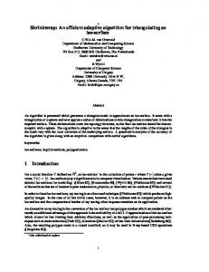
Fig. 1. a) A schematic of the calibration problem considered in this work. The main goal of the paper is to achieve a calibration method to obtain the rigid transformation between the information acquired by a LRF and the stereo camera pair. b) Sketch of the measurement system (dx and dz are the offset distances from the rotation axis to the center of the laser mirror)
model of the environment, visual information, e.g. color or texture, must be acquired. To accomplish this, the laser range finder and the cameras that equip the robots must be extrinsically calibrated, that is, the rigid transformation between the camera and laser reference systems must be known. Previous work regarding the laser-camera calibration issue focus on calibrating the cameras to 2-D laser range finders with both visible and invisible trace [3]. A method to perform the calibration was presented by Zhang and Pless in 2004 and was based on the constraints between views of a planar calibration pattern like the ones used for the intrinsic camera calibration [4]. This method’s calibration error is affected by the angle between the LRF slice plane and the checkerboard plane, therefore the checkerboard needs to be placed at a specific orientation. Another approach from Li et. al. [5] is based on the line constraint equation obtained using a specially designed triangular checkerboard calibration pattern. The recent development of 3-D laser range finders made the use of these scanners more common, even though it still brings some disadvantages, namely some lack of flexibility and the time cost of data acquisition. Nevertheless, 3-D scanners are well suited for particular tasks. Some previous work have been done regarding the 3D laser-camera calibration namely by Unnikrishnan and Herbert [6]. Their method uses a checkerboard as calibration pattern and several laser-
camera acquisitions. Another method to perform the extrinsic calibration, developed by Scaramuzza et. al. [7], obviates the need to have a calibration pattern and uses only point correspondences, hand selected by the user, from a single laser-camera acquisition. In this work the theoretical and experimental results for a novel extrinsic calibration of sensor platform is described. This method is based on a previous approach of Svoboda et al. [8]. In that work, the authors presented a multi-camera self-calibration method for virtual environments using a fully automatic algorithm, in which a freely moving bright spot was the only calibration object. For the purpose of the proposed approach, the internal sensor calibrations are assumed to be known. The platform consists of a 3D-LRF, a stereo camera pair and an inertial measurement unit (IMU). The schematic of the proposed method is shown in Fig. 1(a). As is shown in the figure, the 3D scan data acquisition is achieved using a 2D-LRF and a tilt-unit. A set of virtual 3D points in the stereo pair is made moving a bright spot in front of the platform [8] in three different laser orientations, which are corresponded to real 3D points acquired by the laser range finder. The inertial sensor will provide the angles of this rotations. The high precision of this set of corresponded points allows them to achieve an accurate estimate of the rotation and translation matrices between the stereo cameras and LRF. Then the approach has been extended for a camera network. This document is organized as follows. The extrinsic calibration problem is defined in Section II. Section III describes the geometric models of the stereo camera, 3D laser and inertial measurement unit. Section IV describes the proposed extrinsic laser-camera calibration algorithm. Section V describes an extension of the problem for a camera network. Section VI presents some calibration results. Finally a brief discussion is made on Section VII.
L(α) tC the corresponding (3x1) translation vector. Denote the coordinates of a point p with respect to the CS RF and LRFRF by c p and l p, respectively. Therefore, coordinates are related as follows: c
l
p = L TC p
(2)
For the purpose of this work, the sensor platform only needs three planar scan acquisition in the calibration process. The inertial sensor has been used in order to reliably obtain the angle information, α i , of these three different laser acquisitions. The proposed method achieves the estimate of L(α) TC according to the transformations L(αi ) TC . III. S ENSOR PLATFORM PROJECTION MODEL The goal of the proposed approach is to achieve an extrinsic calibration between a 3D laser range finder and a stereo camera pair, with the aid of an inertial sensor. This section introduces the geometric model of each sensor used in this work. A. LRF geometric Model A 3D laser range finder is usually built by moving a 2D LRF along one of its axes. By rotating the 2D scanner around its radial axes, α, is possible to obtain the spherical coordinates of the points measured. This construction of the laser creates a problem, it is not possible to adjust the center of rotation of the laser mirror with the center of rotation of the laser itself (see Fig. 1-(b)). Therefore, offsets on the measured points will exist [7]. The 3D LRF used in this work was built using a 2D Hokuyo laser mounted on a Directed Perception tilt unit. This type of configuration for the 3D laser can be modeled as follows:
II. P ROBLEM DEFINITION The setup with a LRF, a stereo vision system and inertial sensor for acquiring the environment information is illustrated in Fig. 1-(a). The goal of the method is to find the homogeneous transformation between the stereo camera and the LRF in order to fuse the measuring of the both sensors for robotic applications. As is shown in the Fig. 1(a), three coordinate frames, namely stereo camera (SC RF ), laser range finder (LRF RF ) and the center of the rotation axis (IRF ) have been defined. The SC RF is located in the left image of the stereo pair. Furthermore, the inertial sensor is strongly coupled to the laser range finder, which allows it to assume that both sensors have the same reference frame. Let L(α) TC be the homogeneous transformation between the camera pair and the laser range finder for each angle of the rotation axis α, which is described as � � L(α) RC L(α) tC L(α) (1) TC = 01x3 1 where L(α) RC is the corresponding (3x3) rotation matrix between the laser range finder and the stereo pair, and
⎤ ⎡ x ci cj ⎣ y ⎦ = ⎣ sj −si cj z ⎡
−ci sj cj si sj
si 0 ci
⎡ ⎤ ρij ci dx + si dz ⎢ ⎦⎢ 0 0 ⎣ 0 −si dx + ci dz 1
⎤ ⎥ ⎥ ⎦
ci = cos(αi ), cj = cos(θj ), si = sin(αi ), sj = sin(θj ), (3) where ρij is the j-th measured distance with corresponding orientation θj in the i-th scan plane, which makes the angle αj with the horizontal plane. The offset of the rotation axis from the center of the mirror has components d x and dz . [x y z]T are the coordinates of each point measured relative to the center of rotation of the laser, with the x axis pointing forward and the z axis pointing up. B. Inertial sensor data Basically an inertial sensor includes accelerometer and gyroscope parts [9]. For the aim of this application, just the gyroscope part is used.
C. Stereo camera geometric Model In a pinhole camera model, a point in the space with homogeneous coordinate c p = (x, y, z, 1)T will be mapped to a point p = (u, v, 1)T on the image plane (p is normalized). The point c p in the world reference frame, can be expressed in this coordinate system (such a coordinate system is called the camera coordinate frame [10]), c
p=Hp
(4)
H = KR [I| − C]
(5)
where C and R are the translation and rotation matrices between the camera reference frame and world reference frame and H is called as camera matrix (projective matrix) [10]. This preliminary study for single camera model can be extended to a stereo camera model. This is useful to have 3D position of a seen point by two cameras. Having both two camera matrices, H lef t and H right , and knowing a set t of correspondences, c plef ↔ c pright it is clearly possible i i to compute the 3-D space points w pi using a triangulation method, τ , which is described in [10]: w
t c right pi = τ (c plef , pi , H lef t , H right ) i
(6)
In Eq. (6) the set of points must satisfy the condition F being the fundamental matrix.
t c right pi F plef , i
Fig. 2. a) The proposed approach uses different laser acquisitions in three different planes, which are estimate using the inertial sensor (α0 , α1 and α2 ); and b) The circumcircle of � W P α0 W P α1 W P α2 (shown in a perpendicular view to the X-Z plane of {I} which contains the triangle).
A. Finding L(αj ) TC for three different values of α. In order to calculate L(α0 ) TC , L(α1 ) TC and L(α2 ) TC , the LRF needs to be placed in three different angles around its rotation axis, α0 , α1 and α2 , respectively. These angles are selected taking into account that must exist a field of view intersection between the LRF and stereo camera. An accurate estimate of these three angles are obtained according to the inertial sensor coupled to the laser range finder (see Fig. 2a). Therefore, for the three angles around the rotation axis, the proposed algorithm collects two sets of N 3-D correα spondence points c pαj = {c pi j | i = 1...N, j = 0...2} and l αj l αj p = { pi | i = 1...N, j = 0...2} in both two coordinate references, stereo camera and LRF, respectively. These two sets (for each angle α j ) will satisfy the equation
IV. E XTRINSIC 3D LRF-C AMERA C ALIBRATION
c αj
p
The problem of extrinsic calibration between a tilt 3DLRF and a stereo camera was defined in [7] as finding a transformation matrix L(α) TC . Using this nomenclature, a point seen in the local reference frame of the LRF, LRFRF , can be transformed to the stereo-camera reference frame, SCRF when the LRF has an angle α in its rotation center. The proposed calibration procedure is divided in three consecutive stages. The algorithm is based on the idea of using an intermediate reference frame, I RF , to calculate L(α) TC : 1) Finding L(α0 ) TC , L(α1 ) TC and L(α2 ) TC , which stand for the transformation matrices from the LRF RF to SCRF when the LRF is placed in three different orientations around its rotation axis, α 0 , α1 and α2 , respectively. 2) Finding L(α) TI . This matrix defines the transformation between LRF (α)RF and the center of rotation of the laser range finder, I RF . 3) Calculating the final transformation L(α) TC as the extrinsic parameters between the tilt-LRF in any arbitrary angle and the stereo-camera. These stages will be describe in the next sub-sections.
=L(αj ) RC l pαj +L(αj ) tC
(7)
being L(αj ) RC the rotation matrix, and L(αj ) tC the translation matrix of the homogeneous transformation L(αj ) TC . Therefore, by having { l pαj } and {c pαj } for each one of the three angles, L(αj ) RC and L(αj ) TC can be calculated. Arun’s method, described in [11], is based on an algorithm to find L(αj ) RC and L(αj ) TC such a way that minimize E=
N
||c pαj − (L(αj ) RC l pαj +L(αj ) tC )||2
(8)
i=1
In order to overcome the problem of finding some corresponding points between LRF and camera, a simple laser pointer as a bright spot has been used. The idea of using such as tool for the calibration is originally inspired from an auto-calibration method between multi cameras by Svoboda in [8]. This method is extended in the proposed approach for LRF-camera calibration. The procedure is achieved in three steps for each αj angle: 1) Laser Range Finder data acquisition and preprocessing. A simple method is used to distinguish the bright spot αj αj = {piback (θ, ρ)i | i = from the background. Let l piback
1...nl } be the range data of the background (before putting the bright spot inside the LRF view field) and α l αj pi = {pi j (θ, ρ)i | i = 1...nl } be the range data at the moment, in which n l is number of point read by the LRF, then to detect the laser pointer as a forground abject we can use α |l pi j
−
l αj piback |
>= Uth
(9)
where Uth is a threshold parameter. Thus, in order to α obtain the l pi j set, the scan data is acquired with the laser pointer located out of the LRF´s field of view, which is considered to be planar. Therefore, meanwhile that the LRF is capturing range signals, the bright spot is slowly raising until to hit the LRF’s plane. This procedure is able to be continued to have more than six pairs of 3D points [11]. 2) Stereo-camera data acquisition and pre-processing. As α soon as the point set l pi j is detected and validated using the Eq. (9), the stereo-camera takes two images (left and right) from the scene. The red channel of the acquired images are used to detect the bright spot in α order to compute c pi j [8]. 3) Homogeneous transformation estimate. In this stage, firstly RANSAC is used to remove outα α liers from the point sets l pi j and c pi j [8]. Therefore, α α j j the valid l pi and c pi are used in the Eq. 8 This equation is a least-squares solution to find L(αj ) RC and L(αj ) tC based on singular value decomposition (SVD) as is described in [11]. B. Finding
L(α)
TI
In order to find the transformation between LRF (α) RF and the center of rotation of the LRF, I RF , the following geometrical concepts have been used, which are summarized in the Fig. 2b. Let L(α0 ) tC , L(α1 ) tC and L(α2 ) tC ) be the translation vectors obtained in the previous subsection for each αj angle, respectively. These matrices define a triangle in a 3D space (gray shape in Fig. 2b). As is shown in the figure, the center for the circumcircle of such a triangle is the center of rotation for the LRF, which has been named {I} in the proposed approach. Therefore, the radius of this circle which is also the distance d between I RF and LRF (α)RF can easily be obtained by d=
|L(α0 ) tC
L(α1 )
tC | |L(α1 ) tC L(α2 ) tC | |L(α2 ) tC 4|�L(α0 ) tC L(α1 ) tC L(α2 ) tC |
L(α0 )
tC |
(10) being � the triangle area defined by the translations vectors. Finally, the transformation matrix L(α) TI will be described by ⎡
cos(α) ⎢ 0 L(α) TI = ⎢ ⎣ −s 0
0 1 0 0
⎤ sin(α) d sin(α) ⎥ 0 0 ⎥ cos(α) d cos(α) ⎦ 0 1
(11)
C. Calculating
L(α)
TC
Lets consider the transformation matrix from LRF RF to SCRF as L(α)
TC =I TC L(α) TI
(12)
where I TC corresponds to the transformation between the SCRF and the center of rotation I. In order to obtain the L(α) TC estimate, the transformation I TC must be computed. Eq. (12) represents a homogeneous transformation, which is defined for each α angle. Therefore, L(α) TC can be replaced by the L(α0 ) TC estimate, which was computed in the previous subsection. On the other hand, L(α) TI can be replaced by the matrix estimate in Eq. (11) (by concerning α = α0 in this equation). Finally, the I TC matrix is computed as: I
TC = L(α0 ) TC ( L(α0 ) TI )−1
(13)
Once this I TC matrix has been obtained, the final transformation L(α) TC is estimated according to the Eq. (12) . V. E XTENSION TO A CAMERA NETWORK AND LRF Recently using a camera network has become interesting in surveillance area for the aim of having more coverage on the scene (instead of using just one or two cameras). Hence in this section the argued idea about calibration between a pair of cameras and LRF will be extended for a camera network and LRF. The infrastructure of such a multi-modal sensor network is shown in the Fig. 3. The idea is to do calibration between the stereo camera and LRF using described approach in the Sec. IV and therefore the transformation matrix L(α) TW can be calculated. Then concerning the stereo camera as a member of the camera network in this infrastructure, we can proceed to calibrate all cameras together. In order to do the calibration for a network of camera, Svoboda method [8] is used which is fully automatic and a freely moving bright spot is the only calibration object. A set of virtual 3D points is made by waving the bright spot through the interesting area for the purpose of surveillance. In this method the cameras do not have to see all points and just overlapping between a subgroup of cameras is enough for the algorithm. . The accuracy of Svoboda algorithm is less than 1/5 pixel reprojection error. The procedure for doing calibration for the sensor network described in Fig. 3 is as following stages: 1) Extrinsic calibration between stereo camera and LRF. The method described in Sec. IV can be used to find the extrinsic parameters between the stereo camera and LRF. The result is L(α) TW . 2) Calibration of camera network. In order to calculate intrinsic and extrinsic parameter of the camera network (see Fig. 4), C = {C j |j = 0...4} , Svoboda method described in [8] can be used. In this infrastructure, the stereo camera is considered as a part of camera network (C 0 and C 1 ). The output of
Fig. 3.
The infrastructure of a multi-modal sensor network.
Fig. 5.
Fig. 4.
Point
wp
Smart rooms connected by a corridor.
seen by 5 cameras and a LRF
this stage is a set of 3x4 projection matrices, H = {H Cj |j = 0...4} corresponding to camera C (based on the camera model defined in the section III-C). 3) Reprojection of seen point by LRF into image planes. The point w p which is seen in LRFRF as l(α) p can be reprojected on the image plane ip = {ip Cj |j = 0...4} as u = {uCj | j = 0...4} (see Fig. 4) by the equation u = H L(α) TW
l(α)
p
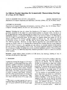
Fig. 6. a) and (b) Real example (left and right images) for one step in collecting some correspondence points by stereo camera and tilt-LRF with the α = 23.2o ; and (c) A simple laser pointer with a red-color plastic is the only calibration object; and b) .
(14)
VI. E XPERIMENTAL RESULTS The proposed approach was tested using the sensor platform shown in Fig. 6a. The stereo head is the STH-MDCS from Videre Design, a compact, low-power colour digital stereo head with an IEEE 1394 digital interface. It consists of two 1.3 megapixel, progressive scan CMOS images mounted in a rigid body, and a 1394 peripheral interface module, joined in an integral unit. Images obtained were restricted to 320x240 pixels. The laser range finder mounted on the tilt unit is an Hokuyo URG-04LX, a compact laser sensor which has a resolution of 0.36 and the field of view of 240. Furthermore, an MTi-G inertial sensor is strongly coupled to the laser range finder. In order to test the robustness and efficiency of the proposed calibration method, a set of virtual 3D points as been generated using the same process described in [8]. The low cost bright spot used in the experiments described in this Section has been illustrated in Fig. 6b. This same virtual points have been acquired by the laser range finder in three different planes. These planes corresponded to α = 12.1 o, α = 23.2o and α = 50o , respectively (these angles were
measured using the inertial sensor). Fig. 6c illustrates a real stereo capture, where the virtual point has been marked (α = 23.2o). The average reprojection error values, in pixels, according to the number of 3-D points used in the method have been represented in Table I. In [11], only six virtual points is considered enough for the calibration purpose. As is shown in Table I, the average error of the proposed calibration method decreases when the method use a higher number of points. It is possible to consider that for N = 18 points, the calibration method is stable. These same results can be obtained analyzing the Fig. 7. In Fig. 7a-b, the evolution of the rotation and translation matrices have been shown, L(α) RC and L(α) tC , respectively. The accuracy of the method is shown in Fig. 8. In this figure, the projection of the laser information in three α planes have been drawn over the left image of the stereo pair (green, red and blue points correspond to α 0 = 2o , α1 = 12o and α2 = 23.2o , respectively). This experiment has been achieved in two different scenarios with similar results. In both two examples, the proposed algorithm demonstrates its applicability for being used in 3D robotic applications.
Fig. 8. Scan data acquired acquired by the laser range finder in three different planes (green, red and yellow points correspond to α0 = 2o , α1 = 12o and α2 = 23.2o , respectively) are reprojected onto the left images of two different scenarios. Fig. 7. Evolution of the rotation and translation matrices estimates by the calibration method according to the number of points used in the approach.
and a LRF. The corridor also has some LRFs, cameras and a mobile robot.
TABLE I C OMPARATIVE STUDY ACCORDING THE NUMBER OF VIRTUAL 3D POINTS . AE
AE SD
= AVERAGE ERROR SD = S TANDARD D EVIATION (P IXELS )
N =6 26.333 5.613
N =9 9.655 3.577
N = 12 6.854 3.130
N = 15 7.080 3.148
N = 18 5.721 2.835
N = 22 5.715 2.807
VII. C ONCLUSIONS AND F UTURE W ORK This paper has presented an efficient method to calibrate a 3D laser range finder and a stereo camera with the aid of an inertial sensor. The approach uses a novel formulation which take into account 3D virtual points detected by the stereo camera using a bright spot. This set of points is easily and reliably selected by both the camera pair and the laser range finder. The same procedure is achieved in three different planes over the rotation axis, where the angular information is estimate by the inertial sensor. Therefore, the two sets of points are corresponded in order to obtain the homogeneous transformation between the camera pair and the range sensor. Experimental results have demonstrated the robustness, efficiency and applicability of the proposed solution. In fact, the approach described in this work requires no special equipment and allows to the researcher to calibrate quickly and in an accurate way the sensor platform. As a future work the idea is to extend this approach for a bigger scenario, where there are two smart rooms and a corridor to connect them. Fig. 5 shows a plan of such a scenario. As can be seen each smart room is equipped with several cameras
R EFERENCES [1] D. Cole and P. Newman. "Using laser range data for 3D SLAM in Outdoor environment" Proceedings of the IEEE International Conference on Robotics and Automation, pp. 1556-1563, 2006. [2] D. Hahnel, W. Burgard and S. Thrun. Learning compact 3D models of indoor and outdoor environments with a mobile robot. Robotics and Autonomous Systems, 44(1):1527, 2003. [3] C. Mei and P: Rives. "Calibration between a central catadioptric camera and a laser range finder for robotic applications", in Proceedings of the IEEE International Conference on Robotics and Automation, pages 532537, 2006. [4] Q. Zhang and R. Pless. "Extrinsic calibration of a camera and laser range finder (improves camera calibration)", in Proceedings of IEEE/RSJ International Conference on Intelligent Robots and Systems, pages 23012306, 2004. [5] G. Li, Y. Liu, L. Dong, X. Cai, and D. Zhou. "An algorithm for extrinsic parameters calibration of a camera and a laser range finder using line features", in Proceedings of the IEEE/RSJ International Conference on Intelligent Robots and Systems, pages 38543859, 2007. [6] R. Unnikrishnan and M. Hebert. "Fast extrinsic calibration of a laser rangefinder to a camera", Technical report, CMU-RI-TR-05-09, Robotics Institute, Carnegie Mellon University, 2005. [7] D. Scaramuzza, A. Harati, and R. Siegwart. "Extrinsic Self Calibration of a Camera and a 3D Laser Range Finder from Natural Scenes", in Proceedings of the IEEE International Conference on Intelligent Robots and Systems, 2007. [8] T. Svoboda, D. Martienc and T. Pajdla. "A Convenient Multi-Camera Self-Calibration for Virtual Environments", PRESENCE: Teleoperators and Virtual Environments, Vol. 14(4), pp. 407–422, 2004. [9] Jorge Lobo. "Integration of Vision and Inertial Sensing". PhD thesis, Electrical and Computer Engineering Department, University of Coimbra, 2006. [10] R. Hartley and A. Zisserman. "Multiple view geometry in Computer Vision". Cambridge University Press, 2003. [11] T. S. Huang, K. S. Arun and S. D. Blostein. "Least squares fitting of two 3-d point sets". IEEE Transactions on Pattern Analysis and Machine Intelligence, Vol. 9(5), pp. 698–700, 1987.