AN EFFICIENT APPROACH TO HIDE THE RUN-TIME RECONFIGURATION FROM SW APPLICATIONS Yang Qu, Juha-Pekka Soininen
Jari Nurmi
VTT Electronics Kaitoväylä 1, Oulu Finland email:
[email protected]
Tampere University of Technology Korkeakoulunkatu 10, Tampere Finland
ABSTRACT Dynamically reconfigurable logic is becoming an important design unit in SoC system. A method to make the reconfiguration management transparent to software applications is required in order to make easier the design with such devices. In this paper, we present an efficient approach similar to the cache miss and the data replacement in modern computer system for the task. The main advantage is that the reconfiguration can be correctly issued without extra instructions inserted either manually by SW application programmers or automatically by compilers. The approach was validated in a real case design. In the Virtex2P20 implementation platform, the resource overhead was 2.45% in terms of the number of LUTs. Performance is measured in cycle-accurate simulation environment. The overhead is about equal when compared with an OS-based equivalent design that uses system calls and critical section code to manage the reconfiguration. 1. INTRODUCTION Complexity, efficiency and flexibility are the main characteristics in future embedded system. SoC platforms that are based on ASICs with embedded processors have difficulties in maintaining these characteristics because of the high NRE cost of the ASIC-type implementation and the processor architecture dependent computation efficiency of the SW-type implementation. In contrary, the reconfigurable systems have the ability to deliver both the performance and flexibility with reasonable cost. The reconfigurability can be achieved by embedding reconfigurable logic into system, and the most common method is to couple them with a host processor [1]. An important coupling technique is to connect them as coprocessors to accelerate computation-intensive tasks. When run-time reconfiguration (RTR) is used, different tasks that are non-overlapping in time frame can be mapped onto a reconfigurable co-processor (RCP) to increase the resource utilization. The overall power consumption can also be reduced if the RTR does not need to be frequently performed [2].
In embedded system design, there are mainly three issues related to RCPs considered as drawbacks. Firstly, mapping of applications onto RCPs tends not to be as efficient as in ASIC design. Secondly, the RTR overhead can significantly decrease the system performance. Finally, design complexity is increased if the configuration process is exposed to application programmers. Extensive research works have been done in these areas. Novel architectures such as coarse-grain reconfigurable logics [3] and domainspecific FPGA [4] have been developed to enable more efficient implementation of certain applications. Prefetching techniques [5] and multi-context devices [6] have been studied to reduce the effect of RTR latency. New OS services [7] have been developed to make the design on RTR devices much easier. Our work belongs to the third area that tries to hide the configuration process from SW applications. We focus on techniques that make RCPs more transparent to SW application programmers. Motivation of the work is as follows. Although the SoC design closely integrates the SW design and the HW design, the two are still separate processes. Changes in the HW platform should be done in a way that near-zero modification in the SW side is necessary in order to increase reusability and productivity. Considering a simple case, a platform consists of a RISC processor and five fixed HW accelerators, and each accelerator is separately controlled via an individual set of memory-mapped registers. Write to one register will trigger an accelerator to run and results are saved in other registers to be read back. In a new version of the device, three of the accelerators are replaced by a RCP unit, but the three accelerated tasks are still controlled using the same memory-mapped technique. However, the compiled SW code for the original HW platform cannot be directly used since the code does not include any instruction or call any OS service to issue reconfiguration. Therefore, the new platform is not backward compatible even the interface between SW tasks and accelerated tasks are the same in both platforms. In this paper, we present a method that can effectively hide the RTR process from SW application programmers by avoiding the use of extra instructions or OS services to issue reconfiguration. The main idea is to treat the RCP in the same way as cache memory, and to seal the “cache management” inside the OS. It should be noted that the
technique does not intend to hide the reconfiguration latency. Instead, it is used to hide the SW-RCP interface so reconfiguration can be correctly issued without inserting extra instructions to the SW applications either manually by SW application programmers or automatically by compilers. The structure of the paper is as follows. The review of related work is given in Section 2. The RTR management method is presented in Section 3. A real implementation and its performance results are given in Section 4. The conclusions are given in Section 5. 2. RELATED WORK Different researchers have addressed issues such as reconfigurable resources sharing and RTR management. Authors in [7, 8, 9] assume that the reconfigurable logic is large enough to simultaneously hold several HW tasks and each task does not need to be allocated to a fixed place. Because of similarities between the HW multitasking and the SW multitasking, solutions based on the OS or even new types of OS are provided. Task relocation and on-line scheduling are studied only in heuristic devices, and routing constraints are not taken into account. The work presented in [10] introduces a modified version of existing device, which allows 2D configuration relocation. However, our RCP models are based on currently available devices that allow partial RTR but not task relocation. In addition, we restrict the model that only one task can be loaded onto the device at a time. This restriction is because we use only one set of master/slave interface to connect a RCP to the system bus. Multi master interfaces are needed to allow multi tasks to be implemented on a RCP simultaneously if they do not happen to occupy the same area. This is however not included in the work. Authors in [11] present a general approach to manage the reconfiguration at the OS level. The access of RCP resources is treated as critical section code, and special system calls are used to handle the configuration process and to manage the contention of using a RCP between different software tasks. However, the OS calls have to be explicitly used, which can be avoided in our case. Techniques and tools [5, 12] to automatically insert special instructions to fetch configuration bits have been proposed. In [5], the work targets on single context device and prefetching techniques have been extensively studied to hide the reconfiguration latency. In [12], the instructions of a core processor and a reconfigurable processor are mixed and stored together in instruction memory, and they are dispatched to the correct target at run time. A special reconfiguration instruction will load the configuration bits, and a backend compiler [13] can automatically generate instructions and combine them. Although in both studies compilers can automatically insert instructions to fetch configuration bits either in advance or in time, the
programmers still need to inform the compiler which part of the code is meant for RCPs, e.g. using the #PRAGMA in the Molen backend compiler [13]. The difference in our work is that no new instruction is need to fetch the configuration bits and thus programmers do not need to care whether the called accelerated tasks are in RCPs or in fixed HW. 3. THE SYSTEM MODEL The tasks that are mapped onto the RCPs can be seen as virtual hardware (VH) [14]. They exist in the system but can be physically accessed only after they are loaded onto the reconfigurable logic. The RCPs have lots of similarity with the processor local cache and the virtual memory, although the first one is for computation purpose and others for storage purpose. In these cases, the “true data” is stored in a low-level unit and a copy of them exists in a local unit. In the memory cases, the “true data” refers to only the normal data. In the case of the RCPs, the “true data” refers to the configuration data stored in the configuration memory and the VH tasks loaded onto the RCPs. When the system needs to access the “true data”, some part of the system will first check if the local unit contains the copy. If so, the access is granted. Otherwise, some procedure is taken into action such as the reconfiguration for a called VH task, the cache miss action in the cache management and the data replacement in virtual memory. The cache miss detection and the data replacement are automatically handled either in the processor hardware level or in the OS level, which significantly reduce the design complexity from application programmers’ points of view. In our approach, the RCP unit is managed in a similar way. The access of an unloaded VH task is treated similarly to the cache miss, and a RTR controller implemented in the hardware side automatically detects the “miss” and handles the replacement for the unloaded VH task. In fact, the approach can also be implemented as SW, but it is only a performance issue. 3.1. System Overview Our technique to automatically issue the reconfiguration process is based on the assumption that accelerated tasks (either implemented in fixed HW or RCPs) are controlled via memory-mapped registers. In addition, the tasks cannot run infinitely once started and they have to assert interrupt signals when finish. For example, a simple implementation of the DCT function requires four registers for controlling the DCT module from the SW. The first one is used to set the starting address of the input data and the second one for the starting address of the results. By writing a non-zero value to the third register, the SW triggers the DCT module to run. After the DCT finishes, it writes non-zero value to the fourth register and asserts an interrupt to issue its finish
of computation. The SW application detects the end of computation using either a polling method or the interrupt. If the DCT module is implemented in a RCP, the DCT task should be loaded before the first write access. In our approach, instead of using explicit instructions to issue reconfiguration, we detect the need of reconfiguration at run time by monitoring the write accesses to the VH tasks. The basic idea is when a write access to a not-configured VH task is detected the write access is delayed and configuration is issued at that point. A general description of the system behavior is as follows. The core of the approach is a RTR controller, a unit inserted between a RCP and the system bus as shown in Fig. 1. It captures all the signals to the RCP and determines when configuration is needed. When a SW task writes to a VH task that has been configured onto the RCP, the writing is performed normally and the SW task continues to run. Otherwise, the RTR controller will push a reconfiguration request of the called VH task into its FIFO queue and send an interrupt signal to the host processor to block the calling SW task. The writing signals are copied to the RTR controller and later on forwarded to the target VH task after it is loaded. Whenever the RCP is free, the RTR controller will load the first request in the FIFO and send an interrupt to the host processor after the loading is finished. HW system
SW system VH task
SW task READY
DONE
BLOCKED
RUNNING
not configured
UNLOADED
DONE
LOADING RUNNING
ready queue FIFO queue
acc
dispatcher interrupt service
OS
WAITING
configured
ess
block | unblock
RTR controller
Reconfigurable logic
Figure 1. Reconfigurable System SW/VH Task State Model 3.2. RTR Controller The RTR controller handles the interface signals connected to the system bus and maintains the states of the VH tasks. The state model of the VH task is presented in Fig. 1. There are five states: UNLOADED, WAITING, LOADING, RUNNING and DONE. Because our assumption that only one VH task is allowed to exist in a RCP at a time excludes the possibility that multi tasks can be ready at the same time, there is no need to have a separate READY state for VH tasks. The UNLOADED means that the VH task is presented only as configuration data stored in the reconfiguration memory. If there is a write access to the VH task, it is moved to either the WAITING or the LOADING. The WAITING means that there is a request to the VH task but
the RCP is occupied by another task. When the RCP becomes free and the task is the first one in the FIFO, it is moved from the WAITING to the LOADING. The LOADING means a copy of the configuration data of the VH task is being transferred to the RCP. The RUNNING means the reconfiguration is done and the VH task is running or ready to be used. In this state, a real image of the VH task is present in the RCP. The VH task will send an interrupt signal after it finishes the execution. The RTR controller will then set its state to DONE when the interrupt is detected. The DONE means the VH task has finished its operation and it can be replaced by a new VH task. In the DONE state, if a write access to the module happens, its state moves to the RUNNING and there is no need to reconfigure the module again. Otherwise, if there is any module waiting in the FIFO queue, the state of this module is moved from the DONE to the UNLOADED and configuration of the first module in the FIFO is started. It should be noted that read accesses do not change the states of the modules, since only results and status are read out and they do not trigger any computation tasks. The RTR controller contains a local copy of the read-back registers of the modules. When a read access happens, if the module is configured (DONE, LOADING, or RUNNING) the value is read from its own registers, otherwise the value is read from the local copy registers of the RTR controller. Prefetching techniques can be implemented in the RTR controller to hide configuration latency. There are two possibilities, static and dynamic. The static approach is only suitable for a known set of tasks. The RTR controller holds a list of tasks and the order of the list is decided during the design time. When the current task is finished, the RTR controller will load the next one in the list. In the dynamic approach, the task priorities are updated at run time, e.g. the most frequently used task has the highest priority. The RTR controller will always load the highest priority task whenever the RCP is free. The current work focuses on hiding the SW-RCP interface, and none of the above prefetching techniques has been implemented. A task is loaded just when it is needed. However, this should not been seen as a drawback of the approach, since the prefetching and our approach are two uncorrelated issues and our approach does not exclude the use of any prefetching technique when needed. 3.3. RTOS and SW Interrupt Service The RTOS contains a FIFO queue for the blocked SW tasks. It is used to ensure that the correct SW task can be unblocked when the configuration of a VH task is finished. This FIFO queue is a separate module from the queue used for the READY tasks in the kernel scheduler. The OS requires two additional interrupt services (ISR), a block service and an unblock service. When the SW task calls a not-configured VH task, the RTR controller sends
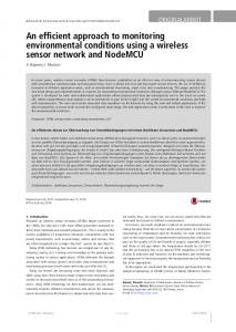
4. A REAL DESIGN USING THE RTR MANAGEMENT APPROACH To validate our approach, we implement the RTR management approach in a real system. The system contains three different SW tasks: a system control task, a video decoding task that drives a DCT (Discrete Cosine Transform) module, and a mathematic calculation task that drives a CORDIC (Coordinate Rotation Digital Computer) module. The DCT module and the CORDIC module are implemented as VH tasks.
number of VH tasks increases or the number of read-back values increase. static region BRAM
PPC
other peripherals
PLB bus IPIC IPIC PLB RTR adapter controller FPGA
CORDIC DCT
SystemACE module
Figure 2. The system structure Correctness of the system behavior has been validated in run time by printing results via serial connection. Fragment of the code is shown in the upper part in Fig. 3. It should be noticed that the way to drive the two VH tasks is the same as they are implemented as fixed HW. Standard GCC compiler in the EDK environment [15] is used, so this validates that configuration is issued without the intervention of SW application programmers or compilers. Table 1. Resource utilization information of the validation system
4.1. Implementation Results The target device is a Memec evaluation board that contains a Xilinx Virtex2P20 FPGA [15]. The FPGA contains two embedded PowerPC cores and supports partial RTR. We divide the whole FPGA into one dynamic region and one static region. Only the two VH tasks are implemented in the dynamic region. The RTR controller and other modules are mapped onto the static region. The configuration is handled via an external SystemACE module [15] that is connected to the static region via IO interfaces. The system structure is depicted in Fig. 2. One PowerPC is used to drive the whole system and the Processor Local Bus (PLB) is used to connect all the modules together. The two ISRs and a small OS with round-robin scheduling technique are implemented, and the full SW package is completely mapped onto internal BlockRAMs [15]. The connection interface between the static region and the dynamic region is a subset of the Xilinx IPIC signals [15], which requires 29 bus macros in implementation. The Xilinx modular design flow [15] is used to generate the partial bitstream. Resource utilization is shown in Table 1. Our RTR controller consumes 455 LUTs, 2.45% of the total LUTs available in the Virtex2P20 FPGA, when not taking into account the PLB adapter. The RTR controller will consume more resources when the
dynamic region
bus macro
the “block” interrupt signal to trigger the block ISR. It will push the current running SW task into the FIFO queue and change its state from RUNNING to BLOCKED. Then, the block ISR will call the kernel scheduler to select a READY task to run. When configuration of a called VH task is finished, the RTR controller sends the “unblock” interrupt signal, which triggers the unblock ISR. It will remove the first SW task from the FIFO queue, set it to READY and resume the interrupted SW task. The unblocked SW will then wait to be dispatched by the kernel scheduler. In this work, RTOS is not considered as SW applications, since it is closely related to the HW platform and is seen as a module belongs to the platform domain. The two ISRs are used only internally by the RTOS and not exposed to SW application programmers.
DCT CORDIC Static modules
LUT 1066 764 3264
BRAM 0 0 34
Multiplier 8 0 0
PPC 0 0 1
4.2. Real-Time Behavior A snapshot of real-time behavior of the system is presented in Fig 3. The SW1 task drives the CORDIC module, VH1. The SW2 task drives the DCT module, VH2. The SW3 does not require any acceleration. Brief description of the behavior is explained as follows. At time t1, the SW1 task writes an angle value to the CORDIC module but it is not loaded. The RTR controller then pushes the request to its FIFO queue and sends an interrupt to the PowerPC. Since there is no other VH task running at this time, the configuration is immediately started. In the OS side, the SW1 is blocked and the SW2 is picked up to run. At time t2, the SW2 writes the start address of the input data to the DCT module, but it is not loaded. The RTR controller then pushes the request to the FIFO and blocks the SW2 task. However, the configuration cannot be started because the CORDIC module is being loaded.
At time t3, the CORDIC module has been loaded onto the reconfigurable region. The unblock-ISR interrupts the SW3, removes the first task (the SW1) from the SW FIFO queue, and sets it to READY. At time t4, the unblock-ISR is finished and the interrupted SW3 task continues to run. At time t5, the external timer expires, which triggers the context switching. The SW1 task is then selected. At time t6, the SW1 task continues to drive the CORDIC module. At time t7, the CORDIC module finishes its operation and the RTR controller starts to copy the results to its readback register file. After that, a new reconfiguration is started for the DCT module, which has been waiting in the RTR controller’s FIFO. At time t8, the configuration of the DCT module is finished. The SW1 is then interrupted. The first task in the SW FIFO queue, the SW2, is set to READY and waiting to be dispatched. At time t9, the unblock ISR finishes, and the interrupted SW1 task continue to run. At time t10, the SW1 is running and issues a read access of the CORDIC module, but the current VH is the DCT module. The RTR controller then returns the data from its local copy of the read-back registers. At time t11, the external timer expires, which triggers the context switching. The SW2 task is then selected. At time t12, the DCT module finishes its operation and the RTR controller starts to copy the results to its read-back register file. It is worthwhile mentioning the configuration behavior specifically at time t1 and time t2. From the SW task point of view, the configuration is issued right after the first writing to the VH1/VH2 tasks, because the SW1/SW2 task is blocked after the write statement. However, the writing cannot be realized since the called VH task has not been loaded. The problem cannot be solved by blocking the SW task before the writing since we do not use any prefetch instruction. In the approach, this is solved by storing signal values of the write access in the RTR controller and later on forwarding them to the target VH task after the configuration is finished, as explained in Section 3. 4.3. Performance Results and Comparisons We have used cycle-accurate simulation approach to measure the run time performance. The SeamlessFPGA [16] co-simulation tool is used, and the DCS method [17] is used to enable the two VH tasks to be simulated in a single environment. Reconfiguration is modeled as pure delays. We measure the overhead related only to the configuration management and compare with an equivalent OS-based design. The overhead of the configuration management TCFG_OS refers to the time spent on handling the configuration from OS point of view. Because
the processor is switched to run other SW tasks when configuration bits are being loaded, the TCFG_OS does not include the configuration latency. The measured results are clearly implementation-specific. However, we carry out the performance evaluation work just to show the effect of the overhead instead of trying to beat any alternative approach. As explained earlier, hiding configuration latency is a separate issue from our approach. Therefore, measurement or comparison involves the configuration latency is not considered, since they are out of the scope of the work. In our approach, the TCFG_OS is calculated as the sum of the time spent on the RTR controller when the first write access happens (TD1 as shown in Fig. 3) and the time spent on the two interrupt services (TIB + TIU as shown in Fig. 3). The measured result is 6676 clock cycles. addr = 0x1000; // the CORDICaddr ... ... // set the angle value *addr = 0x001F; // -------- t1 // start the CORDICcalculation SW1 *(addr+1) = 0x0; // -------- t6 // wait until the CORDICis done while(*(addr+2) == 0); ... ... cos_val = *(addr+3); // -------- t10 t1
t2
t3 t4
t5
addr = 0x2000; // set the DCT addr ... ... // set the input memory addres *addr = 0xF000; // -------- t2 // set the output memory address *(addr+1) = 0xF100; // --------- t11 // start the DCT calculation *(addr+2) = 0x0; // wait until the DCT is done while(*(addr+3) == 0); ... ...
SW2
t6 t7
t8 t9 t10 t11
t12
SW1 SW2
TIU
TD1
SW3
TIB
OS
IB
RTRctnl
D1
IB D1 CFG(1)
IU
CS
CS
D2
CS IU
CFG(2)
CS
R
SW
D2 HW
VH1(CORDIC) VH2(DCT) IB: Interrupt service (block) IU: Interrupt service (unblock) CS: Context switch CFG(n): loading VHtask n R: read values fromreadback registers
D1: RTRcontroller overhead of write access to an unloaded VHtask D2: overhead after a VHtask finishes its operation (different for each VHtask)
Figure 3. Snapshot of Real-Time execution In the equivalent OS-based design, two system calls are provided, rcp_open() and rcp_close(). The code to drive VH tasks is treated as critical section and guarded by the two system calls. The rcp_open() is inserted just before the first write access, so there is also no prefetching. The system calls are implemented using semaphores. The SW task that grabs the semaphore first can access its VH task. If the VH task is not loaded, the reconfiguration is then started, the SW task is blocked, and the PPC is switched to the next READY task. When the configuration is finished, the SW task becomes READY and waits to be dispatched. The TCFG_OS in the OS-based design is equivalent to the time spent on the two system calls. The rcp_open() might trigger context switching, but the related processing time is
irrelevant and so is not measured. The measured result of the TCFG_OS is 8267 cycles. From the measured results, our approach shows 20% less processing time per configuration management. As mentioned earlier, the measured results are implementationspecific and the comparison is used only to validate that our approach does not result in significant overhead. Although the behavior of the OS-based approach and our approach is very similar, they are fundamentally different in that special system calls are inserted to issue reconfiguration in the OSbased case but our case does not use any instruction to issue reconfiguration. 5. CONCLUSIONS In this paper, we have presented an approach to make the run-time reconfiguration management transparent to software applications by using a similar technique to cache miss and data replacement in modern computer system. In the approach, reconfiguration can be correctly issued without extra instructions inserted either manually by SW application programmers or automatically by compilers. The idea is implemented in a real case design that contains two virtual hardware tasks. An equivalent system that uses system calls and critical section technique to handle the reconfiguration management has been implemented. Our approach has been validated in the design and it results in about equal amount of overhead when compared to the OSbased design. Future work would focus on the following directions. The technique would be improved to allow multi tasks to be implemented on a RCP simultaneously. To reduce the effect of configuration latency, prefetching techniques would be included.
[2]
M.G. Lorenz, et al, “Power Consumption Reduction through Dynamic Reconfiguration” FPL2004, LNCS-3203, pp. 751760, 2004.
[3]
Pact XPP Tech., “XPP Datasheets”, www.pactcorp.com.
[4]
K. Eguro, S. Hauck, “Issues and Approaches to coarse-grain reconfigurable architecture development”, FCCM 2003, pp. 111-120. 2003
[5]
S. Hauck, “Configuration Prefetch for Single Context Reconfigurable Coprocessors”, ACM/SIGDA International Symposium on Field-Programmable Gate Arrays, pp. 65-74, 1998.
[6]
Elixent, “D-Fabrix whitepaper”, www.elixent.com.
[7]
C. Steiger, H. Walder, M. Platzner, “Operating Systems for Reconfigurable Embedded Platforms: Online Scheduling of Real-Time Tasks” IEEE Trans. on Computer, Vol. 53, No. 11, pp. 1393-1407, 2004.
[8]
D. Kearney, G. Wigley, “The First Real Operating System for Reconfigurable Computers” Proc. of the 6th ACSAC, pp. 130-137, 2001.
[9]
J. Tabero, et al, “A Low Fragmentation Heuristic for Task Placement in 2D RTR HW Management” FPL04, LNCS 3203, pp. 241-250, 2004.
[10] K.
Compton, et al, “Configuration Relocation and Defragmentation for Run-time Reconfigurable Computing”, IEEE Trans. on VLSI Systems, Vol. 10, No. 3, pp. 209-220, June 2002.
[11] J.S.N. Jean, et al, “Dynamic reconfiguration to support
concurrent applications” IEEE Trans on Computers, Vol. 48, No. 11, pp. 591-602, 1999. [12] S. Vassiliadis, S. Wong, S.D. Cotofana, “The MOLEN rm-
coded Processor”, FPL2001, LNCS-2147, pp. 275-285, 2001. [13] E. Moscu Panainte, K. Bertels, S. Vassiliadis, “The
6. ACKNOWLEDGEMENTS This work is supported by Tekes (National Technology Agency of Finland) and VTT under EUREKA/ITEA contract 04006 MARTES.
PowerPC Backend Molen Compiler”, FPL2004, LNCS3203, pp. 434-443, September 2004. [14] G. Brebner, “A Virtual Hardware Operating System for the
Xilinx XC6200” Proc. 6th International Workshop on Field Programmable Logic and Applications, pp. 327-336, 1996.
[15] Xilinx, “Virtex2P Document”, www.xilinx.com.
7. REFERENCES [1]
K. Compton, S. Hauck, “Reconfigurable Computing: A Survey of Systems and Software” ACM Computing Surveys, Vol. 34, No. 2, pp 171-210, 2002.
[16] Mentor, “SeamlessFPGA Datasheets”, www.mentor.com. [17] P.
Lysaght, J. Stockwood, “A simulation tool for dynamically reconfigurable field programmable gate arrays”, IEEE Trans. on VLSI, Vol. 4, No. 3, pp. 381-390, 1996.