An Efficient Flow Control Algorithm for Multi-rate Multicast Networks
Yan Yang
Naixue Xiong, Yanxiang He The State Key Lab of Software Engineering, Computer School of Wuhan University Wuhan, PR. China
[email protected], yxhe(whu.edu.cn
Department of Computer Science, Central China Normal University, Wuhan, PR. China Y.Yang(mail.ccnu.edu.cn
Jiannong Cao
Chuan Lin The State Key Lab of Software Engineering, Computer School of Wuhan University Wuhan, PR. China
[email protected]
Department of Computing, Hong Kong Polytechnic University, Hung Hom, KLW, Hong Kong, PR. China csjcao(comp.polyu.edu.hk
SR-MCC is that all the receivers must receive data at a single rate, which is the slowest path rate of all relevant paths. This presents a serious practical limitation if we consider, for example, users who are willing to pay more to access at a higher speed. Furthermore, due to the diverse characteristics and requirements of the different receivers within a multicast group, and for greater flexibility in resource allocation, it is desirable to have multicast sessions in which different receivers receive data at different rates. This inflexibility is overcome by MR-MCC that can allocate different rates to different users. Several multicast congestion control approaches [1, 2-19, 22-24] have been proposed recently. One class of approaches [7-9] adopts a simple hop-by-hop feedback mechanism. Although the simple hop-by-hop feature seems to be an advantage, these approaches often lead to the so-called consolidation noise problem [10, 11] due to incomplete feedback information. To overcome this drawback, [11] and [12] proposed the concept of feedback synchronization, at each branch point, by accumulating feedback from all downstream branches. These schemes of [11] and [12] then introduce another problem of slow transient response since the feedback from the congested branch may have to needlessly wait for the feedback from "longer" paths. Such delayed congestion feedback can cause excessive queue build-up and packet loss at the bottleneck link. The authors of [13] and [14] suggested that only a carefully chosen set of receivers, instead of all receivers, send their feedbacks to the sender. Zhang et al. [15] proposed an optimal second-order rate control algorithm to deal with control packet round-trip time (RTT) variation in multicast communications, which defined that the data transfer rate is adjusted at the source depending on the available bandwidth at the bottleneck. More recently, several studies (such as [16-19]) have focused on the design of MR-MCC protocols. However, all of them have drawbacks. Some designs cause over-subscription
Abstract-This paper describes a novel multi-rate multicast congestion control scheme based on the well-known proportional plus integrative control technique, where the control parameters can be designed to ensure the stability of the control loop in terms of source rate. The congestion controller is located at the next upstream nodes of multicast receivers and has explicit rate (ER) algorithm to regulate the rate of the receivers. We further analyze the theoretical aspects of the proposed algorithm, show how the control mechanism can be used to design a controller to support many-to-many multi-rate multicast transmission based on ER feedback, and verify its agreement with simulations in the case of bottleneck link appearing in a multicast tree. Simulation results show the efficiency of our scheme in terms of the system stability, high link utilizations, fast response, scalability, high throughput and fairness.
Keywords- explicit rate, multicast congestion control, multirate multicast, QoS (quality of service), rate-based congestion control
I.
INTRODUCTION
With the ever-increasing multicast data applications, considerable research efforts have been focused on the design of congestion control scheme for multicast service. Multicast improves the efficiency of multipoint data distribution by building a distribution tree from a sender, or multiple senders, to a set of receivers [1]. However, the widely used multicast transport protocols, which are layered on top of the IP multicast layer, could cause congestion or even congestion collapse if they do not provide adequate congestion control. Congestion control thus plays an important role in traffic management of multicast communications, such as teleconference and information dissemination services. There are two approaches of multicast congestion control schemes proposed so far, namely, Single-rate Multicast Congestion Control (SR-MCC) and Multi-rate Multicast Congestion Control (MR-MCC). One obvious limitation of the
0-7803-8836-4/04/$20.00 C2004 IEEE.
74
This research has been supported by National Natural Science Foundation of China under Grant No. 90104005, by the Key Project of Natural Science Foundation of Hubei Province under Grant No. 2003ABA047, and partially by the foundation of the State Key Lab of Software Engineering. Authorized licensed use limited to: Hong Kong Polytechnic University. Downloaded on March 6, 2009 at 04:47 from IEEE Xplore. Restrictions apply.
and high packet losses. Some are slow to converge and unresponsive. Some designs are too complex and infeasible [24]. To address the above problems, this paper describes a novel MR-MCC congestion control scheme based on the proportional plus integrative (PI) controller. The incoming flow rate of a session, at every branching point in its tree, is enforced to be the maximum of the rates that can be accommodated by its participating branches. By doing so, the sending rate at the source will eventually be the maximum of the rates that can be accommodated by the entire paths to individual receivers. Since the source sends data at the maximum path rate, it is necessary to reduce the rate of an incoming flow at every branching point to the value that can be accommodated by its participating branches [24]. The PI controllers are located at the next upstream branch node of the receivers. The relevant gain parameters of the PI controller are determined by the system stability. Each branch point in our scheme only receives feedbacks from the direct downstream nodes instead of all downstream nodes, thus it greatly decreases the number of feedbacks to be aggregated at one node. As a result, our scheme can avoid the so-called feedback explosion problem [24] to a great extent. Simulation results show the efficiency of the proposed scheme in terms of system stability, high link utilizations, quickly response, scalability, high system transport rate, intra-session fairness and intersession fairness. Simulation results verify the efficiency of the proposed MR-MCC scheme. Our scheme is very versatile. It can support sessions where receivers are added and depart. It can manage the traffic to guarantee stability, in real time, even if considerable changes occur in the source-receivers tree. The rest of this paper is organized as follows: In section 2, we present the congestion control model. In section 3, we propose a novel congestion control algorithm, and give the specific pseudocode description of the proposed algorithm. In section 4, we present the optimal choice of the PI control gains and describe the implementations of the PI controller in detail and in section 5, we use simulations to validate and evaluate the performance of our scheme. Finally, in section 6, we end the paper in the conclusions and the future works.
an independently trimmed rate allowed by its entire path. So we acquire the above computed maximum value as the effective sending rate of the multicast source. The sending rate is necessary to convert down the rate of an incoming flow at every branching point to the values that can be accommodated by its participating branches to individual receiver. The
considered multicast elastic service in the network-assisted environments and the relevant parameters are described as follows:
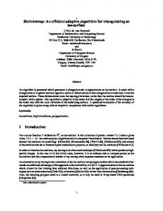
Figure 1. A multi-rate multicast transmission model with single point to multiple points
(1) The network is a connection-oriented one, and time is slotted with the duration [n, n + 1) by the sampling period T. The associated data is transferred by a fixed size packet. (2) In every sampling period, the multicast source issues and transmit forward control packet (FCP) that is turned around by the branch node and destinations, and the backward control packet (BCP) is sent back to the source. (3) After the multicast source receives the BCPs aggregated by the branch nodes, they will take appropriate action to adjust their transmitting rates of multicast traffic based on the maximum sending rate in BCP. (4) The branch node of the multicast session replicates each data packet including FCP and transfers these packets to all its downstream nodes. Moreover, the branch nodes consolidate the BCPs that carry all the available rates and the relevant link bandwidth from different branches into one BCP and feedback the new BCP to their upstream node. (5) After receiving the data packets coming from the network, the receivers construct the BCPs and send them back to the network. (6) The component M is the total number of receivers corresponding the node RT i, (i = 1, 2, ... . m). The maximum number of packets which is allowed by the multicast source to be transmitted into the network in one interval T is denoted by u. (7) For each receiver ji, the buffer occupancy is denoted by xj1 (n) at time slot n and the desired buffer level is denoted by xjj.
II. THE CONGESTION CONTROL MODEL To analyze the performance and characteristic of the multicast, we focus on the following system model as shown in figure 1, where we have two classes of sources, i.e., one multicast source and one end-to-end CBR source. The PI controllers are located at the next upstream nodes of the receivers, i.e., the routers from RT I to RT m , and compute the expected rates used to adjust the multicast receiving rates of the downstream receivers. The receiver ji represents the ith receiver corresponding to the jth router (RT j ). We provide rate adaptation functionality at every branch point of each se4sion. This rate adaptation scheme is determined on the basis of the fact that the multicast tree will eventually receive data at
75
Authorized licensed use limited to: Hong Kong Polytechnic University. Downloaded on March 6, 2009 at 04:47 from IEEE Xplore. Restrictions apply.
(8) The packet number sending out by the receiver ji in one interval T is denoted by Oji, the receiver ji has the
where ak and bk are proportional and integrative parameters, which are to be determined by the stability criteria. The coefficient is used to locate all the poles of the closed-loop system (2) and (3) within the unit circle to ensure the stability. The component xji is the target queue length. In (3) it is seen that, if the buffer occupancy of the receiver ji is measured at the instances n -rji, after the feedback delay rji the BCP reaches the controller located at the next upstream node RT j (j = 1, 2, ***, m) and the router then takes out the buffer occupancy of the destination nodes at time t = n. By doing so, the designed controller can be expected to have flexibility to cope with the sharp oscillation in buffer occupancy which will lead the network to lose packets. In addition, the calculation in (3) is completely independent of virtual connections travelling through the multicast tree, which means the scheme has scalability. Figure 1 depicts the proposed congestion control model of single point to multiple points in a multicast network. The sending rate at the source will eventually be the maximum of the rates that can be accommodated by the entire paths to individual receiver. So it is necessary to convert down the rate of an incoming flow at every branching point to the values that can be accommodated by its participating branches. The incoming flow rate at every branching point is enforced to be the maximum of the rates that is also expected by corresponding receivers [24]. i.e., the receivers j send the BCPs (Back Control Packets) to the next upstream branch node RT j as soon as they receive the FCPs (Forward Control Packets), then PI controller located at RT j computes the
forward delay rii from the next upstream branch node to itself, the round-trip delay (RTD) between the next upstream branch node to itself TRji = 2ji, and Ai =
max( -rRjls N2 *... 9 rRjM ).
We
further
assume that ri and VRji are integers, which are reasonable by adjusting T. And the link delay is dominant compared to the other delays such as proceeding delay and queuing delay, etc. (9) Each router schedules the packets in a first-come-firstservice way. The component Rj (n) represents the receiving rate of the computed receivers j at time slot n, and R c (n) denotes the transmission rate at CBR source at time slot n. Under the above notations and assumptions, the buffer occupancy of the receiver jI is determined by
xji (n + 1) = SatK..{xji (n) + RJ (n - rI )-J} Where Kji is the buffer size, xi (n) is the
(1) buffer
occupancy of the receiver ji at time slot n, and
Rj (n -rji ) is the sending rate of the next upstream branch
node
Sat
to
K
ji
ji }
{
the
K ji , X ji
0,
receiver
ji.
x3i > K ji ; °O < x ji < K ji;
expected rate R for the receivers at the next period T according to equation (3). Moreover, every branch node merges BCP including the sending rate Ri and selects the
x 1i < O;
After lifting the saturation restriction, equation (1) can be written into
xji (n + 1)=xji (n) + Rj (n - Tji) - Oji
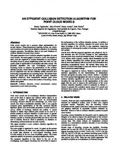
maximum of the rate R = max(R1,R2, . , R), then feedback the value to the next upstream node until the value R is feedbacked to the multicast source. Then, the multicast source adjusts the incoming flow rate in terms of the feedback maximum sending rate. Since the source sends data at the maximum rate including FCP, the independently trimmed rate R, which is the rate allowed by its entire path, satisfies the best-effort service for all the receivers j . Before we present the algorithm in details, we specify the following variables. The multicasttree[i] = 1(0) means the Ith branch point receive (don't receive) FCP or BCP control packet; while receivertree[i] = 1(0) means the ith branch point receive (don't receive) confinmations of all receivers. Based on the above specifications, the pseudocode of the proposed router and source algorithms are given in Figure 2.
(2)
III. THE ALGORITHM The key component of the proposed congestion control algorithm is the way to compute the required source rate matching with the destinations' buffer. If xji (n) is too high, it
often leads to buffer overflowing and packet loss. If xj (n) is too low, it increases the likelihood of link underutilization during occasionally idle period. Thus the router buffer occupancy plays an important role in the congestion control. In this paper, we firstly propose the following PI controller, which is located at the next upstream node of each receiver and is updated upon every T epoch for MR-MCC.
Rj (n) =/1+ k=1Z ak(Xjk (n- jk )- Xjk )+ k=1 bkRj (n -k) (3) 76
Authorized licensed use limited to: Hong Kong Polytechnic University. Downloaded on March 6, 2009 at 04:47 from IEEE Xplore. Restrictions apply.
adopted AIMD (addictive increase and multiplicative decrease) (see, for example [20]). For example, in AIMD, it is difficult to choose the appropriate increase and decrease factors to guarantee the system's stability and then to obtain smooth and healthy rate adaptation and good link utilization. In this section, the stability of the proposed PI congestion control scheme is analyzed as follows. Considering the proposed controller of equation (2), if ztransformation is applied, one can easily arrive at
Source Algorithm Upon every T epoch Transmit data including FCP; Upon multicast source receives a consolidation BCP from its downstream Adjust the transmitting rates in terms of min(the maximum receiving rate of corresponding receivers in the consolidated BCP, the bandwidth of the connective link);
(z - 1)Xji (z) = z " Rj (z) - OjD(z),
Router Algorithm If multicasttree[i]= =1
where the z-transformation of xji (n), Rj (n) are described by
if the packet is an FCP Put the data packet in the buffer; Multicast the data packet including FCP to the downstream nodes;
+00
+00
n=O
n=O
Xji(z) = Zxji(n). z , R1(z) =
else
+00
and D(z)=Zzn=
If the node is the next upstreamn node of the receiver j
n=O
z-n
Z
z-1
M
R
k=1
k=1
Rj (z) = uD(z) + Zak(z ikXjk(z) -XJkD(z)) + Zbkzk Rj (z)
Select the maximum expected incoming rate of the next downstream node; } Construct the BCP based on the received BCPs and the relevant case; Feedback it to the upstream node; if receivedtree[i]==1 { Delete the data packetsfrom the buffer; else ( Maintain the data packets in the buffer until Receive all confirmations of the receivers;}
(5)
From equation (4) and (5), one has M
Az* Rj(z) =-Eak (LD(z)z k=1
jk + DXJk(z)(z -1))
and
} Receiver Node Algorithm
( jY
M
k=l
k=l
(6)
The coefficients ak and bk (k = 1, 2, ,) are determined by the stability criteria of the control theory. From a control-theoretic view when all the zeros of (6) lie within the unit disc, the original network system (2) with the controller (3) is stable in terms of in terms of the source's emitting rate. Stability in terms of sending rate is a prerequisite in congestion control to ensure that the network has no oscillation of sending rate and thus minimizes the packet loss rate. Without loss of generality, we group those nodes into one class,
Upon receipt of an FCP Put the data packets into the buffer; Construct the BCP based on the current case of the receiver nodes; Feedback the BCP to the upstream branch point;
Figure 2. Pseudocode of source/ router/ receiver algorithms
IV.
Rj(n)
Taking the z-transform of equation (3), one yields
Compute the expected sending rate R i for the receivers i using PI controller;} else
{
(4)
IMPLEMENTATION OF PI CONTROLLER
which have a small variation of time delays and sending rates. Thus we divide receivers j (j = 1, 2, * **, m) into q groups based on the RTTs, and in each group, the RTT is assumed to be equal, i.e.,
A. Control Gain Selections We use a rate-based rather than a window-based adaptation algorithm to achieve congestion control in MR-MCC tree. The window-based scheme has extra complexity in maintaining and synchronizing the congestion window across all receivers, it usually generates data bursts periodically. In our proposed PI control scheme, the rate adaptation takes into account the receivers' buffer occupancies as well as the variation of RTTs. The controller parameters are designed to guarantee the stability of rate, which ensures a smooth dynamic of rate adaptation to minimize the packet loss rate. This in turn brings an obvious advantage of the proposed scheme over the widely
;, IRjM}-{tl, * * tl, t2, * * t2,**; tq q and we set n1is the number of the RTT t, (l = 1, 2, .. q)
{TRJ1 ,z'R]2I ,Rj3
q
corresponding to the / th group receivers, then M = E n,). 1=1
77 Authorized licensed use limited to: Hong Kong Polytechnic University. Downloaded on March 6, 2009 at 04:47 from IEEE Xplore. Restrictions apply.
We
j E [1, r
b=[b lb2 b
re s I
bj = j-1- na, a, =M ], i zE[1,M],n E [0, M]. if j < TRlx n = 0;
set
TABLE I.
\Recelver
else rRI < 7Ri < i