functional verification of RTL circuit descriptions written in. HDL. The FSM coverage ..... designer to write a HDL program with state-by-state style for. FSMs with ...
An Efficient Functional Coverage Test for HDL Descriptions at RTL Chien-Nan Jimmy Liu
and
Jing-Yang Jou
Department of Electronics Engineering National Chiao Tung University, Taiwan, R.O.C. jimmy @ EDA.ee.nctu.edu.tw , jyjou @ bestmap.ee.nctu.edu.tw
Abstraction Until now, simulation is still the primary approach for the functional verification of RTL circuit descriptions written in HDL. The FSM coverage test can find all bugs in a FSM design. However, it is impractical for large designs because of the state explosion problem. In this paper, we modify the higher level FSM models used in other applications to replace the FSM model in the FSM coverage test. The STGs can be significantly reduced in this model so that the complexity of the test becomes acceptable even for large designs. This model can be easily extracted from the original HDL code automatically with little computation overhead. The experimental results show that it is indeed a promising functional test for FSMs.
1. Introduction Until now, simulation is still the primary approach for the functional verification of the initial register-transfer level (RTL) descriptions written in hardware description language (HDL). The major problem of this approach is to choose a good metric to gauge the quality of the test vectors. A lot of coverage metrics have been proposed for HDL [1, 2] based on traversing the language structure. They can verify the correctness of each atomic action written in the HDL programs but are difficult to find the bugs related to the sequence of actions. Another approach, which is called the FSM coverage test [1], verifies the functionality by applying input patterns to traverse the whole state transition graph (STG) of a finite state machine (FSM) during the simulation. This exhaustive test can find all bugs in a FSM design. However, the sizes of the STGs in modern designs are often too large to be traversed completely. Although several techniques [3, 4, 5] can reduce the huge sizes of STGs by separating the datapath from the control circuits, it still consumes a long simulation time to verify the resultant STGs. In order to cope the state explosion problem, some techniques model FSMs at a much higher level of abstraction, such as the EFSM [6] and the HLSM [7]. The STGs of FSMs can be dramatically reduced in the higher level models. If we apply the higher level FSM models to test the functionality of FSMs, the simulation time could be dramatically reduced, too. In order to match the requirement of HDL functional verification, we make some modification on the higher level FSM models. Our model can keep the FSM structure to verify the sequence of actions, and use the content of HDL descriptions to greatly reduce tests. The experimental results show that it is indeed a promising functional test for FSMs. In this paper, the definition of the proposed SFSM model is given in Section 2. In Section 3, we present an automatic algorithm to extract the SFSM model from the original HDL codes. The experimental results are provided in Section 4. This work was supported in part by Novas Software Incorporation and R.O.C. National Science Council under Grant NSC89-2215-E-009-009.
2. The Semantic Finite State Machine Model Consider an 8-bit counter with synchronous load and reset functions as shown in Figure 1. Because the HDL can express the behaviors in higher level of abstraction, we can describe the counting behavior by using a simple statement such as count = count + 1 instead of using a case statement with 28 branches. Furthermore, because the HDL-based synthesizers are in production use for many years, it is reasonable to assume that they are so robust that they hardly produce buggy circuits for the datapath operators such as plus operator. Therefore, it is a better practice to simulate the descriptions of the same behavior only once instead of verifying the same behavior repeatedly in large amount of different states. Then the verification time can be greatly reduced without sacrificing any quality assurance. module counter ( clk, reset, load, in, count ) ; input clk, reset, load ; input [7:0] in ; output [7:0] count ; reg [7:0] count ; always @( posedge clk ) begin if ( reset ) count = 0 ; else if ( load ) count = in ; else if ( count == 255 ) count = 0 ; else count = count + 1 ; end endmodule Figure 1 : A counter example written in Verilog HDL. Our proposed Semantic Finite State Machine (SFSM) model is developed based on the above observation. We group the explicit states with the same behavior into one semantic state. The transitions between the explicit states included in the same semantic state are eliminated, and the transitions between different semantic states are kept to make sure the FSM has the correct sequence of actions. Therefore, the SFSM model is a reduced subset of the conventional FSM model. Definition 1 : A Semantic Finite State Machine M is defined as the 7-tuple { S , V , I , O , U , A , T }, where S is a set of semantic states, V is a set of state variables in the original FSM, I is a set of input symbols, O is a set of output symbols, U is a set of update functions for the state variables such that U : S×V×I→V, A is a set of action functions for the outputs such that A : S×V×I→O, T is a transition relation such that T : S×V×I→S.
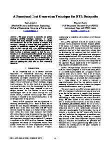
Definition 2 : An update function is a statement consisting of assignments, logic operations, and arithmetic operations only. The left-hand-side variable of this function is restricted to the state variables. The right-hand-side variables of this function will be expanded recursively until they are constants, the primary inputs, or the state variables of the FSM. Definition 3 : An action function is defined similarly as the update function except the left-hand-side variable of this function is restricted to the primary outputs only. The SFSM model can also be represented by a graph. The vertices of this graph correspond to the semantic states in the SFSM model. In each semantic state s, there is an update function us ∈ U which updates the state variables of the FSM. There is a directed arc t labeled as f (v, i) / at from vertex p to vertex q in the graph if there is a transition of T(( p, v, i ) →q ). The function f (v, i) is called the enabling condition of this transition. The action function at ∈ A updates the outputs of the FSM while this transition occurs. This graph is named as the semantic state transition graph (SSTG). In Figure 2, we show the SSTG of the counter shown in Figure 1. There are only three different behaviors in this counter. Therefore, there are three semantic states in the SSTG. All the possible enable conditions are listed on the right of Figure 2 with an unique label. The enabling condition of each transition is referenced with this label. Because there are no other outputs except the state variable count, the action function of each transition is not shown in Figure 2. C1
C1 : reset
C2 : (! reset) load
C3 : (! reset) (! load) (count == 255)
count =0 C4 C1
C2 C1 C3
C4
count = count+1
C4 : (! reset) (! load) (count != 255)
As an example, the statement tree including the update functions for the FSM shown in Figure 1 is shown in Figure 3. reset == 1
count = 0
reset == 0 load == 1
count = in
load == 0 count == 255
count = 0
count != 255
count = count + 1
Figure 3 : The statement tree for the FSM in Figure 1. Step 2 : Build the semantic states in the SFSM model. Definition 5 : Two update functions or two action functions y , z are equivalent iff for each statement in y , there is a corresponding statement with the same left-hand-side variable existing in z and those two statements are identical. While the statement tree of the HDL code is built, we check all terminal nodes in the statement tree and group the nodes with equivalent u and a functions into one semantic state. The semantic state to which each terminal node belongs is recorded in the data structure of the terminal node. Step 3 : Calculate the enabling condition of each transition.
C3 C4 C2
Definition 4 : A statement tree is a rooted, directed graph with vertex set N containing two types of vertices. A nonterminal vertex n has one or more children child(n) ∈ N. A mutual exclusive condition, which is composed of constants, the primary inputs, or the state variables, is attached on each edge from n to child(n). A terminal vertex n, which represents the terminal block in the HDL code, has no children but a set of update functions Un and action functions An . All the implicit descriptions, which retain the previous value of variables, are also specified in Un and An.
count = in
C2
Figure 2 : The SSTG of the example in Figure 1. In this example, there are 256 states and 66047 transitions in the conventional STG. However, there are only 3 states and 11 transitions in the SSTG. If we want to satisfy 100% FSM coverage in the conventional STG, it will take at least 66047 clock cycles in simulation. In our SFSM model, only 13 clock cycles are needed to reach 100% SSTG coverage. Therefore, the verification time can be dramatically reduced.
3. Automatic SSTG Generation from HDL Because the verification process starts with the designs written in HDL, we develop a simple algorithm to automatically extract the SSTG from the HDL descriptions. The extraction is done in four steps as follows : Step 1 : Generate the statement tree of the FSM. The first step is to parse the HDL structure of the synchronous section of the FSM to build the statement tree. The synchronous section is the HDL code which describes the next-state and output equations of this FSM. The statement tree is defined as follows.
The product of the conditions on the path from the root to the terminal node in the statement tree is the enabling condition which enables the transition from some other semantic states to this semantic state. In other words, each enabling condition represents a transition going to the particular semantic state corresponding to this terminal node. After traversing the statement tree, all possible enabling conditions can be obtained. Step 4 : Build the transitions between semantic states. Definition 6 : An accumulated enabling condition e is contradictory to a semantic state s iff ∃ u ∈u s s.t. e ⋅ u ≡ φ . For each semantic state, we can check all the enabling conditions to find the transitions going out from this state. However, some transitions do not exist because of condition contradiction. After eliminating those contradictory transitions of each semantic state, the SSTG of the FSM can be obtained.
4. Experimental Results To conduct experiments, we applied the proposed SSTG extraction algorithm to five FSM examples. The design statistics are given in Table 1. The column lines gives the line numbers of the HDL code. The columns PIs and POs are the bit numbers of primary inputs and primary outputs respectively. The column SRegs gives the bit numbers of all state registers.
Design bjk cnt8 alarm cnt32 rankf
lines 163 14 102 14 553
PIs 9 11 32 35 13
POs 8 8 29 32 8
SRegs 4 8 17 32 88
Table 1 : Design statistics. The extraction results, which are obtained on a 300MHz UltraSparc II, are shown in Table 2. The results give a good comparison between the sizes of conventional STGs and our SSTGs. Even for the cases that the STGs are extremely large, such as the design cnt32 and rankf, the sizes of SSTGs remain reasonable to be handled. In addition, the computation time is quite small for all cases. It shows that the SSTG extraction process incurs almost no computation overhead. Design bjk cnt8 alarm cnt32 rankf
STG states 16 256 86400 232 ≈ 288
STG edges 39 66047 ≈ 864002 ≈ 264 ≈ 2176
SSTG states 16 3 7 3 65
SSTG edges 39 11 37 11 4099
CPU time (second) 0.07 0.01 0.05 0.01 2.11
Table 2 : Experimental results of SSTG extraction. In Table 2, we can find that the reduction on graph size is significant except the design bjk. In this design, the designer describes the behavior of the FSM state by state. Therefore, no reduction can be gained from the HDL code. Fortunately, the state explosion problem is not serious in those cases because the numbers of states are often small. It is very uncommon for a designer to write a HDL program with state-by-state style for FSMs with hundreds of states. Therefore, the SFSM model can be kept in a reasonable size for various FSMs. Another interesting observation can be obtained from the examples cnt8 and cnt32. When the number of bits of the counter increases, the number of states in the conventional STG grows exponentially but the number of states in the SSTG remains the same. It is due to the fact that our SFSM model is built on higher level of abstraction. The influences of bit numbers have been eliminated. Definition 7 : State Coverage Metric (SCM)
SCM =
Number of semantic states visited Total number of reachable semantic states
Definition 8 : Transition Coverage Metric (TCM)
TCM =
Number of transitions traversed in the SSTG Total number of reachable transitions in the SSTG
With the same designs, we use another experiment to compare the line coverage test against our SSTG coverage test and show the experimental results in Table 3. For each design, we generate test vectors in three different ways. Due to the limited computation resources, we stop generating vectors when the number of patterns exceeds 10000. The number of vectors generated is given in the row “#Vec”, and the line coverage is given in the row “LCM”. The rows “SCM” and “TCM” give the state coverage and transition coverage in the SFSM model, which are defined in Definition 7 and Definition 8.
Method \ Design #Vec Directed LCM for SCM SFSM TCM #Vec Directed LCM for SCM LCM TCM #Vec LCM Random SCM TCM
bjk 111 100% 100% 100% 49 100% 100% 67% 10000 94% 94% 95%
cnt8 13 100% 100% 100% 4 100% 100% 36% 2205 100% 100% 91%
alarm 54 100% 100% 100% 10 100% 100% 27% 10000 97% 86% 68%
cnt32 13 100% 100% 100% 4 100% 100% 36% 10000 75% 100% 82%
rankf 10000 100% 100% 87% 71 100% 71% 1.7% 10000 79% 63% 3.9%
Table 3 : Comparing coverage metrics. According to Table 3, the line coverage always achieves 100% when the SCM and the TCM reach 100%. That means our SSTG test can completely cover the line coverage test, which is considered to be the basic requirement for HDL functional testing. In addition, from the data in the test “Directed for LCM”, we can find that the TCM of each design is still low when line coverage achieves 100%. That means many transitions between actions are not traversed in the line coverage test. Some errors in the sequence between actions may still occur. Furthermore, the numbers of vectors needed in the directed tests are always less than the numbers in random tests. The coverage of random vectors are also lower than those of directed vectors. Therefore, in terms of achieving 100% coverage metric, we find the directed vectors to be superior to the random vectors for FSM designs. Even for the designs with large STGs, such as the designs cnt32 and rankf, we can still test them with high coverage by reasonable numbers of vectors.
5. Conclusions In this paper, we modify the higher level FSM models used in other applications to replace the FSM model in the FSM coverage test. The STGs can be significantly reduced in this model so that the complexity of the test becomes acceptable even for large designs. The experimental results show that the proposed SFSM model can be efficiently extracted from the original HDL code automatically and it is indeed a promising functional test for FSMs.
References [1] D. Drako and P. Cohen, “HDL Verification Coverage”, Integrated Systems Design Magazine, June 1998. [2] T.-H. Wang and C. G. Tan, “Practical Code Coverage for Verilog”, Int’l Verilog HDL Conf., 1995. [3] Richard C. Ho and Mark A. Horowitz, “Validation Coverage Analysis for Complex Digital Designs”, ICCAD, Nov. 1996. [4] Dinos Moundanos, Jacob A. Abraham, and Yatin V. Hoskote, “Abstraction Techniques for Validation Coverage Analysis and Test Generation”, IEEE Trans. on Computers, 47(1):2-14, Jan. 1998. [5] Chien-Nan Liu and Jing-Yang Jou, “A FSM Extractor for HDL Description at RTL Level”, The Fifth Asia-Pacific Conference on Hardware Description Languages, Seoul, Korea, July 1998. [6] K.-T. Cheng and A. S. Krishnakumar, “Automatic Functional Test Generation Using the Extend Finite State Machine Model”, 30th DAC, 1993. [7] Andreas Kuehlmann and Reinaldo A. Bergamaschi, “High-Level State Machine Specification and Synthesis” , ICCD, Oct. 1992.