IEEE MICROWAVE AND WIRELESS COMPONENTS LETTERS, VOL. 11, NO. 5, MAY 2001 ... K. K. Chui was with Hughes Space and Communications Company, Los An- geles, CA 90009 USA. .... New York: Wiley, 1980. [14] H. J. De Los ...
IEEE MICROWAVE AND WIRELESS COMPONENTS LETTERS, VOL. 11, NO. 5, MAY 2001
193
An Efficient HBT/RTD Oscillator for Wireless Applications Héctor J. De Los Santos, Kelvin K. Chui, David H. Chow, and Howard L. Dunlap
Abstract—In this paper, we introduce a novel HBT/RTD oscillator suitable for monolithic integration and efficient low power/battery-operated applications. Implementation of a circuit prototype was accomplished by configuring an InP-based monolithic HBT/RTD chip with a gold wire bond inductor in a hybrid microwave package. For an output frequency of 5.8 GHz, the circuit draws a current of 15.5 mA from a 1.5 V supply and dBm, for an efficiency of generates an output power of 8.84%.
+3 13
Index Terms—HBT, oscillator, quantum device, resonant tunneling, RTD, wireless.
I. INTRODUCTION
L
OW power consumption is key to enabling future portable wireless applications [1]–[3]. Because of their small size and radical operating principles, quantum devices (QDs) have demonstrated the potential for highest speed/lowest power-consumption operation [4], and these properties are beginning to be demonstrated in many of the circuit/system functions employing them [5]–[12]. One circuit/system of high importance, but which has received very little attention in the context of its realization based on QDs, is the sinewave oscillator. Sinewave oscillators are at the heart of communications systems, where they are used to establish transmitter carrier frequencies, drive mixer stages that convert signals from one frequency to another, and generate clocking signals [13]. Of particular interest are wireless communications systems such as satellites or portable systems, where low-power consumption and high frequency performance are important. With this context in mind, we focus in this letter on the exploitation of a resonant tunneling diode (RTD), in conjunction with a heterostructure bipolar transistor (HBT), to realize an efficient HBT/RTD oscillator circuit [14]. II. NOVEL HBT/RTD OSCILLATOR: CIRCUIT, IMPLEMENTATION AND PERFORMANCE A. Circuit Description The novel HBT/RTD oscillator circuit shown in Fig. 1(a) was first disclosed in [14]. It consists of an HBT and RTD Manuscript received September 14, 2000; revised February 22, 2001. This work was supported in part by the Defense Advanced Research Projects Agency and the Office of Naval Research under Contract N00014-94-C-0251. H. J. De Los Santos was with Hughes Space and Communications Company, Los Angeles, CA 90009 USA. He is now with COVENTOR, Inc., Irvine, CA 92606 USA. K. K. Chui was with Hughes Space and Communications Company, Los Angeles, CA 90009 USA. He is now with Boeing Satellite Systems, Inc., El Segundo, CA 90245 USA. D. H. Chow and H. L. Dunlap are with the HRL Laboratories, LLC, Malibu, CA 90265 USA. Publisher Item Identifier S 1531-1309(01)04011-9.
configured with an inductor in a negative resistance oscillator and , topology [13]. The supply and bias voltages respectively, are so chosen that the HBT is biased at collector and collector-emitter voltage that set the current in its negative differenRTD DC operating point sets the tial resistance region, Fig. 1(b). In turn, HBT transconductance which determines the output voltage , across the total collector resistance, , swing, about and, thus, oscillator output power. A small-signal model of the oscillator circuit is shown and model the RTD, and and in Fig. 2, where are functions of the HBTs small-signal transconductance , input resistance , output resistance , collector node , the emitter inductor and frequency. parasitic capacitance In terms of these parameters it can be shown that the frequency of oscillation is approximately given by [14]
This expression will prove useful for future full monolithic implementation of the circuit, as it captures the relation between oscillation frequency and key HBT and RTD device electrical parameters. It also elucidates one important aspect of the HBT, namely, the degree to which the intrinsic oscillation frequency capability of the RTD can be approached, will hinge , or maximizing the HBTs [17]. As upon minimizing indicated by the above formula, and also contemplated in [14], this topology might be implemented with a bipolar junction transistor (BJT) as well. In addition to its simplicity, the HBT/RTD oscillator introduced here has a number of important advantages over previous RTD-based oscillators [4]. For instance, it consumes much less power, as much as 90% less, than known feedback oscillators. can be much lower, for example Indeed the single supply 1.3 V because it must only supply the voltage drops across the RTD, which may be as low as 0.1 V [15], [16], the HBTs active region collector-emitter, and the inductor . This not only extends the life of the battery, but also allows a smaller battery, suitably 1.5 V, to be used. Also, unlike the known negative resistance waveguide oscillators [4], the HBT/RTD oscillator is suitable for monolithic integration, using either the III-V compound technology currently used for RTDs or the silicon or gallium-arsenide technology used for HBTs. Although the HBT/RTD oscillator consumes slightly more power than the waveguide oscillator and has a lower quality factor, the size, cost, reliability, and reproducibility advantages associated with monolithic integration more than offset these disadvantages. Alternatively,
1531–1309/01$10.00 ©2001 IEEE
194
Fig. 1.
IEEE MICROWAVE AND WIRELESS COMPONENTS LETTERS, VOL. 11, NO. 5, MAY 2001
(a) HBT/RTD oscillator circuit and (b) RTD dc bias condition.
(a)
(a)
(b) Fig. 2. (a) RTD circuit model and (b) HBT/RTD oscillator small-signal circuit model.
the RTD and HBT can be fabricated in discrete chips, which is still cheaper, more reliable, and easier to mass produce than the waveguide oscillator.
(b)
B. Implementation and Performance
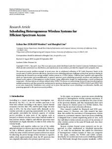
Fig. 3. HBT/RTD oscillator performance: (a) room temperature output spectrum and (b) output power versus temperature.
An indium phosphide (InP) based technology was used for the implementing the active part of the circuit. heterojunction bipolar transistors
(HBTs)
were
monolithically resonant
integrated tunneling
with diodes
DE LOS SANTOS et al.: EFFICIENT HBT/RTD OSCILLATOR FOR WIRELESS APPLICATIONS
(RTDs) in a coplanar geometry. The epitaxial layers for the two device structures were deposited in a single growth run by molecular beam epitaxy on an InP wafer which is patterned by photolithography and dry etching prior to growth. The substrate pattern consists of pedestals, which support RTDs after postgrowth device fabrication, and a lower level which ultimately supports HBTs. Details of the integration process have been reported elsewhere. [16] HBTs fabricated in this process have typical current gain of 40–60 and unity gain cutoff frequencies approaching 100 GHz. The RTDs were designed A cm , with a to yield a peak current density near peak-to-valley current ratio of 10 and a peak voltage position of 0.3 V. The HBT/RTD chip was die-attached using Silver epoxy to a 450 square mil ceramic package [12]. The device contacts were wire bonded to dc bias pads and the inductor was realized with a Gold wire of 1 mil diameter and a length of approximately 130 mils. Fig. 3 shows the measured oscillator performance for the hybrid circuit prototype. With a supply voltage of 1.5 V, the circuit draws a current of 15.5 mA and dBm, Fig. 3(a); this equates delivers an output power of to DC efficiency of 8.84%. The temperature performance of the intrinsic HBT/RTD oscillator, i.e., with no attempt made at temperature-compensation, Fig. 3(b), reveals an output power dBm C between C and C. variation of Future work will address noise performance.
III. CONCLUSION We have presented the description, implementation, and output power and efficiency performance of a novel [14] HBT/RTD oscillator circuit suitable for monolithic integration and low-power/battery operated wireless applications. In particular, the circuit has the potential to exploit the high-frequency/low-power characteristics of the RTD within a monolithic context and thus opens the way for insertion in high-volume applications.
195
REFERENCES [1] G. H. Heilmeier, “Personal communications: Quo vadis,” in Proc. IEEE Int. Solid-State Circuits Conf. Dig., Feb. 1992, pp. 24–26. [2] A. A. Abidi, “Low-power radio-frequency ICs for portable communications,” Proc. IEEE, pp. 544–569, Apr. 1995. [3] H. J. De Los Santos, Introduction to Microelectromechanical (MEM) Microwave Systems. Norwood, MA: Artech House, 1999. [4] F. Capasso, Ed., Physics of Quantum Electron Devices. Berlin, Germany: Springer-Verlag, 1990. [5] K. J. Chen, K. Maezawa, and M. Yamamoto, “InP-based high performance monostable-bistable transition logic elements (MOBILEs) using integrated multiple-input resonant tunneling device,” IEEE Electron Device Lett., vol. 17, pp. 127–129, Mar. 1996. [6] P. Mazumder, S. Kulkarni, M. Bhattacharya, J. P. Sun, and G. I. Haddad, “Digital circuit applications of resonant tunnelling devices,” Proc. IEEE, vol. 86, pp. 664–686, Apr. 1998. [7] C. Pacha, U. Auer, P. Gloesekoetter, A. Brennemann, W. Prost, F.-J. Tegude, and K. Goser, “Resonant tunneling transistors for threshold logic circuit applications,” in Proc. 9th IEEE Great Lakes Symp. VLSI, Ann Arbor, MI, March 4–6, 1999. [8] J. P. A. van der Wagt, A. C. Seabaugh, and E. A. Beam, III, “RTD/HFET low standby power SRAM gain cell,” IEEE Electron Device Lett., vol. 19, pp. 7–9, Jan. 1998. [9] W. Williamson et al., “12 GHz clocked operation of ultralow power interband resonant tunneling diode pipelined logic gates,” IEEE J. SolidState Circuits, vol. 32, pp. 222–231, Feb. 1997. [10] W. Prost, U. Auer, C. Pacha, G. Janßen, R. Bertenburg, W. Brockerhoff, K. Goser, and F. J. Tegude, “InP-based HFETs and RTDs for high speed digital circuitry,” in Proc. Symp. Signals, Syst., Electron., Pisa, Italy, 1998. [11] U. Auer, W. Prost, G. Janssen, M. Agethen, R. Reuter, and F. J. Tegude, “A novel 3-D integrated HFET/RTD frequency multiplier,” IEEE J. Select. Topics Quantum Electron., vol. 2, pp. 650–654, Sept. 1996. [12] H. J. De Los Santos, K. K. Chui, D. H. Chow, and H. L. Dunlap, “DHBT/RTD-based active frequency multiplier for wireless communications,” in Proc. 1997 IEEE Int. Symp. Compound Semiconductors, San Diego, CA, Sept. 8–11, pp. 515–518. [13] H. L. Krauss, C. W. Bostian, and F. H. Raab, Solid State Radio Engineering. New York: Wiley, 1980. [14] H. J. De Los Santos, “Bipolar junction transistor(BJT)-resonant tunneling diode (RTD) oscillator and circuit method,” U.S. Patent 5 883 549, Mar. 16, 1999. [15] H. Fukuyama, T. Waho, and T. Mizutani, “Current-voltage characteristics of GaAs/AlAs double-barrier resonant tunneling diodes with a Si-planar-doped barrier,” J. Appl. Phys., vol. 79, no. 3, Feb. 1996. [16] D. H. Chow, M. Hafizi, W. E. Stanchina, J. A. Roth, J. J. Zinck, J.-J. Dubray, and H. L. Dunlap, “Monolithic integration of resonant tunneling diodes and heterojunction bipolar transistors on patterned InP substrates,” J. Vac. Sci. Technol. B, vol. 16, p. 1413, 1998. [17] S. M. Sze, Physics of Semiconductor Devices, 2nd ed. New York: Wiley, 1981.