that will become hardware into a synthesizable subset of a hard-. Permission to make digital/hard copy of all or part of this work for personal or classroom use is ...
An Efficient Implementation of Reactivity for Modeling Hardware in the Scenic Design Environment Stan Liao� Steve Tjiang� Rajesh Guptay � Advanced Technology Group, Synopsys, Inc.
y Dept. of Information and
Computer Science, UC Irvine.
Abstract—Reactivity is one of the key features of hardware description languages. We present an efficient implementation of reactivity in the Scenic framework that allows the system designer to model hardware blocks. Scenic allows the designer to use C++ to model mixed hardware–software systems with a C++ compiler and a small library and without the need of a complex event-driven run-time kernel often found embedded in hardware description languages (HDL) such as VHDL and Verilog. Moreover, Scenic hardware descriptions can be easily mapped to HDL and synthesized into hardware implementations using commercially available tools. In this paper we present Scenic’s implementation of concurrency (signals and processes) and reactivity (waiting and watching). When C++ is used as an HDL, context-switching overhead can become a significant performance issue during simulation. We introduce the notion of delayed expression objects, or lambdas, to reduce context-switching. Examples and experimental results are presented to show the utility and simulation efficiency using the Scenic framework. I. INTRODUCTION The high level of integration afforded by advances in processing technology has brought new challenges in the design of digital systems. Higher integration has spurred a trend to integrate entire complex systems—consisting of a heterogeneous mixture of hardware and software components—into systemon-a-chip designs [5] [6] [7] [17] [19]. The trend challenges CAD-tool developers to provide tools that can support the design of such hardware–software systems. Several researchers (e.g., [7] [9] [12] [17]) have proposed various methodologies for the hardware–software co-design of digital systems. Commercial tools have addressed some of the issues in co-design such as hardware–software co-simulation [9] [15]. One of the most pressing issues in hardware–software codesign is that of design entry—the lack of a single language in which to describe both hardware and software components. A single language would facilitate seamless hardware–software co-simulation. Moreover, a single language would facilitate the step-by-step refinement of a system design down to its components. Today, a system designer would write system-level models in a high-level programming language such as C or C++. The designer can estimate system performance and verify functional correctness of the designs using commonly available software compilers. However, to implement the design using synthesis, the designer must manually translate those parts of the model that will become hardware into a synthesizable subset of a hardPermission to make digital/hard copy of all or part of this work for personal or classroom use is granted without fee provided that copies are not made or distributed for profit or commercial advantage, the copyright notice, the title of the publication and its date appear, and notice is given that copying is by permission of ACM, Inc. To copy otherwise, to republish, to post on servers or to redistribute to lists, requires prior specific permission and/or a fee. c 1997 ACM 0-89791-920-3/97/06 ..$3.50 DAC 97, Anaheim, California
ware description language (HDL), such as Verilog or VHDL. This process is often tedious and error-prone. Scenic simplifies the process by supplying a single language framework—based on C++—in which the designer describes both hardware and software components. It delegates the complexities of handling hardware semantics to a library of class and methods, thereby facilitating the development of hardware descriptions from existing algorithmic code. In Scenic, we stipulate only that hardware components be synchronous, a weak limitation since most hardware designs are synchronous. We use C++’s facilities to implement hardware-modeling features that can be automatically mapped into synthesizable HDL. Designers can thus continue to use widely available standard compilers and debuggers to verify their designs, and to use commercially available synthesis tools to implement their hardware. A typical design flow in the Scenic framework begins with an untimed description in C++, using a library of new data types useful for modeling hardware. The description can be compiled and simulated for functional correctness. Then, the design may be refined by adding interface specificaiton and timing information, and again the timed description can be compiled with a standard C++ compiler, simulated, and debugged. This paper concerns the implementation of reactivity, a key feature useful for describing hardware. In Section II we discuss requirements in modeling reactivity and its effects. In Section III we describe our implementation of reactivity in the Scenic environment using delayed expression objects. We have written models for moderately complex systems and successfully verified them with modest amount of effort, and we show the advantages of usingdelayed expression objects. Section IV concludes the paper by summarizing the results and plans for future work. II. REQUIREMENTS FOR MODELING HARDWARE Specifically, we can model a hardware system as a reactive system: a system in continuous interaction with its environment. That is, we think of and express (in HDL) hardware as a set of nonterminating processes that react continuously to events in their environment [2]. Kurshan [13] first introduced the concept of reactive behavior, and the concept has since been used in the area of process-control and real-time systems [1], [4]. A notable language based on the notion of reactivity is the synchronous language Esterel [4]. The concept of reactivity appears in Verilog and VHDL as signals and events (a change in a signal’s value) as well as the ability to recognize and respond to events. All existing HDLs incorporate reactivity in using an event-driven model. Reactivity is sufficient to describe most hardware systems at various levels of abstraction: from algorithms to gate-level circuits. However, the use of HDLs in system modeling, architectural evaluations and hardware–software co-design has been mixed at best. One reason for this disappointing result has been the overhead of event processing. Another reason is that HDLs
often do not have the facilities to describe software in an efficient and natural way. HDLs typically have poor facilities to describe data structures. They do not integrate seamlessly to existing software libraries. In Scenic, we approach hardware description by starting with C++, a programming language familiar to most designers when they write software, and unburdened by event processing overhead. The framework uses the object-oriented facilities of C++—subtyping and templates—to implement reactivity in a manner natural to hardware designers, and to assist designer in modeling data-types (e.g., standard logic of VHDL) and structural elements for hardware (e.g., ports and port maps). A. Modeling Reactivity In Scenic, we provide a class library in C++ to support reactivity. Reactivity support requires the following: Concurrency or Parallelism. Hardware is inherently parallel. Concurrency in operations can be modeled using support for program threads and co-routines in the form of libraries. We encapsulate concurrency in an object or class definition. We can then build non-terminating hardware processes by using the subtyping and virtual-function facilities of C++. Signals and Events. Hardware processes require signals and events to communicate. We use templates to provide the concept of signals on which events will be detected. Although thread/concurrency libraries for C++ provide other communication primitives such as semaphores and critical regions, such primitives are better suited for software because they usually assume that processes have easy access to each other’s states— in other words, it is possible to refer to a process’ internal variables. This assumption is ill-suited for hardware modeling and synthesis. Waiting and Watching. Hardware processes interact through events and signals. Thus they need the ability to wait or watch for a particular condition or event. Waiting refers to a blocking action (as in “wait until (expression)”) that can be associated with an event. Watching refers to a non-blocking action that runs in parallel with a specified behavior (as in “do p watching s”). This construct is used typically to handle preemptions [3]; the semantics is such that regardless of the state of execution of p, whenever s occurs, p is terminated. B. Modeling Structures and Data Types In addition to describing behaviors, the ability to describe structures is essential to hardware modeling. A structural description consists of component instances and their interconnection as in a net-list. Two central notions in modeling structures are those of ports and port maps. Scenic models ports using C++ references to signals; signals, in turn, are entities to which ports are mapped. Port mapping takes place at object instantiation time, and the constructor of each process object is responsible for binding signal arguments to the object’s ports. An example will be shown in Figure 2. Another practical feature of HDLs is the use of multiplevalued logic for representing unknown or don’t-care values. Scenic provides the same feature by defining a new aggregate type std_ulogic and overloading the logic operators. A complete implementation of std_ulogic and std_ulogic_vector, as well as bitvector-based signed
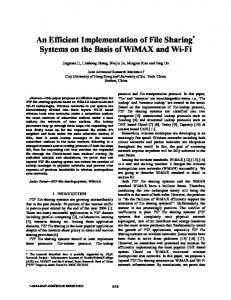
and unsigned arithmetic, is an integral part of the Scenic environment. C. Simulation of Reactive Systems This section provides some background on the Scenic implementation of reactivity by outlining two of the methods to execute models of reactive systems: event-driven and processdriven. Both methods implement processes as either coroutines or threads. Event-driven simulation remains the primary means of executing a model of a reactive system. Traditional event-driven simulators such as those used to implement HDLs maintain a notion of simulated time as well as tracking every write to signals; signal writes can be scheduled to occur at a future simulation time. A write that changes the value of a signal generates an event that can resume waiting processes or divert the control-flow of watching processes. An event-driven simulator requires a complicated scheduler that maintains time and lists of pending signal writes, as well as lists of waiting and watching processes for each signal. In process-driven simulation, processes check for signal changes and conditions on which they are waiting or watching. In the extreme, this can reduce to busy-waiting, an expensive proposition. For synchronous systems, it is often sufficient to perform the checks during clock changes. Some cycle-based simulators use this approach [8]. The process-driven approach, however, may incur many context-switch operations. Event-driven simulators best suit hardware models in which each process is small with only a few inputs and event activity is low—there are few events per unit of simulated time. For such models, an event-driven approach avoids unnecessary computation. For example, an event-driven simulator would avoid evaluating a gate if its inputs has not changed. When event-activity is high or when processes are large with lots of inputs (more inputs means the probability that all inputs remain unchanged is low), the overhead in the scheduler may overwhelm the savings from avoided computations. In system and behavioral models where large processes read and write many signals, the cycle-based simulation offer higher speed. For this reason, microprocessor designers usually build a C-model and simulate using their own cycle-based simulator [8] [18]. As we have intended Scenic for use for systemlevel or behavioral modeling, Scenic implements a cycle-based simulator. Unfortunately, we have little control over contextswitching costs in C++ and these costs can quickly become a bottleneck. For this reason, Scenic uses a hybrid of event-driven and process-driven approaches. Scenic retains a simple scheduler that tracks only clock signals but the checks on signal changes and condition have shifted from processes to the scheduler to reduce context-switching overhead. In the following section we discuss the issues in maintaining simulation efficiency. III. IMPLEMENTATION OF SCENIC AND SIMULATION RESULTS The Scenic environment consists of a library of classes and methods that support hardware modeling. Since a complete description of the library is out of the scope of this paper, we focus on our implementation of processes and reactivity. Fig. 1 shows a high-level view of clocks and processes in the Scenic environment. A hardware model consist of a set of
clk1
clk2
wait
wait wakeup
wait
wakeup proc1
proc2
proc3 signals
Fig. 1. Clocks and processes at a glance. Processes are suspended by transferring control to its clock (via a wait message), and are continued when the clock issues wakeup. Processes communicate through signals. class Counter : public sc_process { const sc_signal& enable; sc_signal& iszero; int count; public: Counter( sc_clock_edge& EDGE, const sc_signal& ENABLE, sc_signal& ISZERO ) : sc_process(EDGE), enable(ENABLE), iszero(ISZERO) { count = 15; // initialization } void entry(); };
(a) ENABLE
enable
EDGE
clock
iszero
ISZERO
(b) Fig. 2. (a) Declaration of the Counter class in C++. (b) The corresponding structure.
processes. Each process is mapped to a thread with its own stack space (execution state). Currently, we use a nonpreemptive thread (co-routine) package [10] for mapping sequential processes. Events generated by each process is synchronized by an associated clock. Each event is identified as a delayed signal assignment, and the associated action is passed onto the clock processes. A process synchronizes with its clock by issuing to it a wait message. The clock processes are responsible for performing the actions (signal updates) at the end of the cycle and for waking up the processes thereafter. A. Describing Process Behaviors A process class is declared by publicly deriving, or subtyping, from the library base class sc_process, thereby inheriting the fundamental capabilities of a process that are defined in the Scenic library. An example is shown in Fig. 2. The constructor for Counter takes as arguments a clock and the signals that comprise its interface. The initializers in the constructor passes on the clock for base-class initialization (sc_process(EDGE)), and binds the port names to internal signal names. The behavior of the user-defined process is separately specified in the member function entry(), as shown in Fig. 3. The examples demonstrate the use of two basic features of
void Counter::entry() { if (enable.read() == ’1’) { if (count == 0) { write( iszero, ’1’ ); count = 15; } else { write( iszero, ’0’ ); count--; } } next(); } Fig. 3. Body of the Counter process. int main() { sc_signal enable; sc_signal iszero; sc_clock clk; Counter counter(clk.pos(), enable, iszero); sc_clock::press_start_button( 1000 ); } Fig. 4. Instantiating a process and starting the simulation
the Scenic library: write() and next(). Calling write() places an event on the clock’s list of actions. For instance, write(iszero, ’1’) schedules an update for the signal iszero, for the next clock edge. The statement next() synchronizes the process with the next clock edge. Note that the function entry() behaves as a VHDL process; that is, its body is repeatedly executed, even though there is no explicit enclosing loop. B. Instantiating Processes In the Scenic environment, a process is instantiated just as any object is instantiated in C++, by defining a variable of the appropriate process class and supplying arguments to the constructor. In Fig. 4, we create the signals enable and iszero, a clock, followed by instantiation of a process of type Counter, and then we begin the simulation for 1000 cycles. In this example, the pos() method is used to obtain the positive edge associated with the clock. (Of course, this code fragment serves only as an illustration and does not do anything useful since there is no stimulus.) It is important to note that the declaration and definition of a process class defines a behavior, whereas defining a variable of a particular class creates an instance. Therefore, we can conceivably create several instances of the same process class without duplicating code or explicitly passing objects as arguments. Object-oriented languages such as C++ offer a less cumbersome way to create instances than procedural languages. C. Reactivity: Waiting and Watching We now describe our implementation of reactivity—waiting and watching. We introduce the notion of delay-evaluated expressions, and then present two implementations that explore the trade-offs in expressiveness and efficiency. We then describe how delay-evaluated expressions are used in conjunction with the C++ exception handling mechanisms to implement watching.
Waiting. A waiting process suspends itself until some event occurs. For example, a process may, after its initialization, wait for a signal start to be asserted before starting its operation. In VHDL one can write: wait until start = ’1’;
Using this wait for a synchronous digital circuit requires that signal start be sampled at a clock edge. This is accomplished as follows: loop wait until clk’event and clk = ’1’; exit when start = ’1’; end loop
The analogous expression in Scenic is: do { next(); } while (start.read() != ’1’);
While this achieves the desired effect, it is not very efficient in practice. Every call to next() causes a context switch to the next process in the clock’s process-list or to the clock, and in some machines context switches can be expensive. The context switches to and from the current process serve only to evaluate the expression E on which the process is waiting. If the evaluation of E can occur outside of the current process, we can avoid many unnecessary context switches, because instead of unconditionally switching back to the process to evaluate E, our decision to switch is now based on the value of E—only when E evaluates to true in the current cycle do we switch. To permit other processes to evaluate the expression E, a process must have a way of making E known externally. Therefore, E must be delay-evaluated, because if we were to write the expression as shown above, it would be evaluated immediately and we would be left with a value not an expression. The key here is to create an object that encapsulates the expression to be evaluated and which provides a method eval() that allows anyone with a handle to the object to force its evaluation. We call such delay-evaluated expressions lambda expressions or simply lambdas (so named because the semantics resemble the �-abstraction operation in �-calculus [16]). We present two different implementations of lambdas. Static Lambda Creation. One way to implement lambdas is to use a closure [16] that consists of a function and a set of arguments serving as the function’s environment of evaluation. For example, we use the following function to represent the condition we set out to wait on. bool signal_is_1(sc_signal& s) { return (s.read() == ’1’); }
A lambda is created simply by supplying a pointer to the function and the signal start which will be passed to the function when the evaluation is forced: sc_lambda start_is_1( signal_is_1, start );
where sc_lambda is the library class that represents a lambda object. Then, in the body of the process, we can write: wait_until( start_is_1 );
to pass to the clock process the static lambda object start_is_1. At each edge the clock process evaluates the
lambda by invoking the method eval(), which effects the application of the function part (signal_is_1) to the argument part (start). The suspended process is waken up only if the result is true. Dynamic Lambda Creation. A serious disadvantage of static lambda creation is that the designer has to write the function representing the lambda and explicitly instantiate the lambda object. This is certainly unintuitive and error-prone. We simplify the creation of lambdas by allowing the designer to write: wait_until( start == ’1’ );
This takes advantage of C++’s ability to overload operators. Here we overload the operator == such that, when a signal appears in the expression, a lambda object is created. In this case, no user-defined function such as signal_is_1 is involved; the lambda object is represented as an expression tree. Evaluation of the lambda object consists of interpreting the tree at run-time. Thus, dynamic lambda objects are less efficient than static ones; the loss is not too significant, however, because most expression trees are very small. The reader must have noticed that we have previously written (start.read() == ’1’), but here we write (start == ’1’) instead. The difference is important and the designer must bear it in mind: in the former we evaluate the expression immediately, but in the latter a lambda is created and passed as argument to wait_until(). Watching. As we have seen in Section II-A, another important property of reactive systems is the capability to react to preemptions or interrupts [3]. One of the most commonly used preemption in hardware design is the use of reset, which, regardless of the present state of the system, always brings the system to the reset state. It is the system’s responsibility to watch for preemptions at all times. It is one area where the ability of existing HDLs such as VHDL and Verilog to model interrupts is severely lacking. For instance, even assuming that all signals (including those carrying preemption) external to process are synchronized at clock boundaries, VHDL requires the designer to test for such signals at every clock boundary: wait until clk’event and clk = ’1’; exit reset_loop when reset = ’1’;
where reset_loop is the outermost loop that encloses the reset sequence and the main loop. If pre-synthesis and postsynthesis simulations are to yield the same results, then these statements are required. This is tolerable if reset were the only preemption that is being watched. However, as we add more preemptions for the process to watch for, the code can become quite unwieldy. Furthermore, if we explicitly check for preemptions on every clock boundary, we would not be able to take advantage of the delayed evaluation of lambda expressions, since the preemptive conditions may occur at any time, in particular before the lambda evaluates to true. We agree with Berry et al. that support for preemption should be orthogonal with respect to other constructs [3]. We have found an elegant way to solve this problem using the C++ exception handling mechanism, namely try, catch, and throw. In Scenic, each process has a watch-list, to which lambda expressions are added during object instantiation. All
Counter::Counter() { watching( reset == ’1’ ); watching( pwr_dn == ’1’ ); watching( test == ’1’ ); } (a) void Counter::entry() { try { /* BODY OF PROCESS */ } catch (sc_user&) { if (reset.read() == ’1’) /* DO RESET */ else { if (pwr_dn.read() == ’1’) /* DO POWER DOWN */ if (test.read() == ’1’) /* DO TEST */ } } } (b) Fig. 5. In Scenic, preemptions to watch for are registered in the constructor, and the handling is accomplished using try/catch. (a) Preemptions are registered in the constructor. (b) Preemption handling is carried out in the catch block.
the lambdas on the watch-list will be evaluated on every clock edge. For instance, the statement in the user-defined constructor watching( reset == ’1’ );
creates a lambda corresponding to the condition that signal reset is raised, and registers this condition with the watch-list. Fig. 5 shows an example with several preemptive conditions. The member function entry() uses the try/catch construct to implement the handling of preemptions. A C++ exception of type sc_user is thrown from the next() or wait_until() functions. These functions receive a notice from the clock process when one or more of the lambdas in the watch-list evaluate to true, and instead of returning normally, they throw an exception which is caught by the catch block. The code within the catch block handles the preemptions. Note that only one type of exception, namely sc_user, is thrown. This design decision allows maximum flexibility for the handlers when two or more preemptions occur during the same clock cycle. For example, the user may decide to prioritize the preemptions or to take special actions for various combinations of preemptions. In Fig. 5, the handlers are written such that: � reset has the highest priority and is handled exclusive of the other two conditions; � pwr_dn has a higher priority than test but they are not exclusive; in other words, if both signals are raised in the same cycle, the actions for pwr_dn will be executed first, and then those for test. D. Clock-Level Asynchrony: Support for Multiple and Nonisochronous Clocks Most real systems, though primarily synchronous, contain some form of asynchrony, either in the form of multiple clocks, or in signal handling even if in restricted places. In this section we describe the modeling of multiple clocks that are non-
Example 2 FSMs IDCT PrioQ
C++ lines 103 308 633
Na¨ıve 8.3 10.0 21.4
Static 7.4 7.7 17.0
Dynamic 7.5 8.6 18.8
Table I. Comparison of simulation times for various examples: na¨ıve, static lambda, and dynamic lambda implementations. CPU times are seconds measured on an UltraSparc (Solaris 2.5).
isochronous with respect to one another [14]. In other words, while each process is synchronous with respect to the clock that drives it, the periods and phases of clocks need not bear any rational relationship with one another. To implement clock-level asynchrony, we first attach two attributes to clocks, namely objects of type sc_clock: the period of the clock, and the time instant at which the clock begins running. For instance, the following declares two clocks which respectively have periods 2 and 3 time units, and begin running at time instants 0.0 and 0.5:
p
p
sc_clock clk1( 0.0, sqrt(2.0) ); sc_clock clk2( 0.5, sqrt(3.0) );
Each clock object is also responsible for keeping record of the time instant when its next edge will take place. When the function sc_clock::press_start_button() is called, the clocks are placed on a priority queue, ordered by the time of their next edge. In a sense we are using an event queue as in any full event-driven simulator; the difference is that the only events in our system are clock edges, and process-level events, synchronized on these edges, are not explicitly manipulated at this level. E. Simulation Results We have written several moderately complex models, along with test-benches, in the Scenic environment. We have compiled the models and the libraries with the GNU C++ compiler, version 2.7.2. Table I shows the examples and the simulation times for 100,000 behavioral cycles. (It is important to note that cycles at this level do not necessarily correspond to machine cycles since the synthesis tools may expand a behavioral cycle into several machine cycles.) Since GNU C++ does not yet support exception handling with code optimization, the simulation speed shown here will be significantly faster as the quality of the compiler is improved. Nevertheless, the results demonstrate significant speed-up achieved by the use of lambdas. Table I shows the simulation times for several examples. “2 FSMs” refers to two interacting finite state machines, each with its own clock. “IDCT” is an implementation of the inverse discrete cosine transform from [11]. Finally, “PrioQ” is an implementation of a priority queue with inheritance for an ATM switching controller. In this table, the na¨ıve construct refers to the following form: do { next(); } while (! condition);
which is a common implementation of reactivity in existing HDLs. Using static lambdas resulted in a speed-up of about 20%. Since most lambda expressions are very small, the difference between static and dynamic lambda creation is less pronounced.
ACTION Signal assignment Wait on clock
BEHAVIORAL VHDL
SCENIC
dout