works by first applying DWT (Discrete Wavelet Transform) to the input image to yield ... KeywordsâCopy-Move forgery; digital signature; digital image forensics ... researchers have developed techniques for detecting this form of image forgery.
Er. Saiqa Khan et. al. / (IJCSE) International Journal on Computer Science and Engineering Vol. 02, No. 05, 2010, 1801-1806
An Efficient Method for Detection of Copy-Move Forgery Using Discrete Wavelet Transform Er. Saiqa Khan Computer Engineering Dept., M.H Saboo Siddik College Of Engg., Mumbai, India
Er. Arun Kulkarni Information Technology Dept., Thadomal Shahani Engineering College., Mumbai, India
Abstract—Copy-Move forgery is a specific type of image forgery, in which a part of digital image is copied and pasted to another part in the same image. This paper describes blind forensics approach for detecting Copy-Move forgery. Our technique works by first applying DWT (Discrete Wavelet Transform) to the input image to yield a reduced dimension representation [1]. Then the compressed image is divided into overlapping blocks. These blocks are then sorted and duplicated blocks are identified using Phase Correlation as similarity criterion. Due to DWT usage, detection is first carried out on lowest level image representation. This approach drastically reduces the time needed for the detection process. Keywords—Copy-Move forgery; digital signature; digital image forensics; DWT; phase correlation
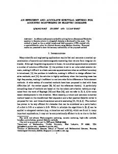
I. INTRODUCTION Advanced digital cameras and newest photo-editing software packages make it relatively easy to create digital image forgeries. There has been some effort in the digital signature and watermarking communities to detect and locate image manipulation. But the limitation in digital signature or watermarking technology is that the media data must be preprocessed when it is established, such as calculating hash values, or embedding watermark in the images. This makes the scope of their application greatly constrained. A specific form of digital tampering is Copy-Move forgery, in which a part of the image itself is copied and pasted into another part of the same image to conceal an important object. Because the copied part come from the same image, its important properties, such as noise, color palette and texture, will be compatible with the rest of the image and thus will be more difficult to distinguish and detect these parts. In Fig.1, an example of copy-move forgery can be seen; where the original image (Figure 1(a)) has two different original emblems whereas in forged one (Figure 1(b)), cloning tool of Photoshop has been used to hide one of them using other emblem from the original image itself. Several researchers have developed techniques for detecting this form of image forgery. Since the key characteristics of Copy-Move forgery is that the copied part and the pasted part are in the same image, a direct method to detect this forgery is exhaustive search, but it is computationally complex and more time is needed for detection. Therefore, this correlation can be used as a basis for successful detection of a forgery by looking
ISSN : 0975-3397
(a)
(b) Figure 1. Example of Copy-Move forgery (a) original image (b) tampered image
for identical image regions [2]. To make the computation quicker, J.Fridrich proposed an effective blocking approach, in which the image blocks are represented by quantized DCT (Discrete Cosine Transform) coefficients, and a lexicographic sort is adopted to detect the Copy-Move blocks [3]. A.C.Popescu developed a similar method by applying the Principal Component Analysis (PCA) to yield a reduced dimension representation [4].G. Li developed a sorted neighborhood method based on DWT (Discrete Wavelet Transform) and SVD (Singular Value Decomposition) [5].The DWT and SVD method suffers from the drawback that the computation of SVD takes lot of time and it is computationally complex. In this paper, a wavelet based approach is presented where the usage of wavelet transform for compression of tampered image has been tested and phase correlation is used as similarity checking criterion for identifying duplicity of overlapping blocks formed from the tampered image. The multiresolution analysis feature of DWT has been explored. Since exhaustive comparisons of blocks have been applied only on the image in the lowest resolution level, the approach has significantly improved the time and accuracy of detection compared to the past techniques of Copy-Move forgery.
1801
Er. Saiqa Khan et. al. / (IJCSE) International Journal on Computer Science and Engineering Vol. 02, No. 05, 2010, 1801-1806 II. PROPOSED ALGORITHM The work on “Detection of Copy-Move forgery in digital images” is implemented in two phases as described below. A. First Phase This phase deals with detection of reference and matching blocks on the lowest level of wavelet transform compressed image as shown in Figure 2 [1]. RGB image
using Discrete Wavelet Transform is to reduce the size of the image at each level, e.g., a square image of size 2j ×2j pixels at level L reduces to size 2j/2 × 2j/2 pixels at level L+1. Methods can differ in the type of the wavelet applied. At each level, the image is decomposed into four sub images. The sub images are labeled LL, LH, HL and HH. LL corresponds to the coarse level coefficients or the approximation image. This image is used for further decomposition. LH, HL and HH correspond to the vertical, horizontal and diagonal components of the image respectively. An example image along with its wavelet transform applied up to level 3 is shown in Figure 4.
Gray scale conversion Wavelet Transform Overlapping block pixels into a matrix Maximum contrast blocks selection Matrix sorting Phase correlation calculation between rows Candidate block co-ordinates into a new matrix
Candidate blocks Figure 2. Detection of Reference and Match Blocks
B. Second Phase This phase deals with checking on different DWT levels to produce more robust output as shown in Figure 3.
Figure 4. An image and its Wavelet Transform
These sub images can be combined together to restore the previous image which was decomposed. Due to this, DWTs are used for iterative comparison of matching blocks. If the number of levels used for decomposition is ‘L’, then the matching performed on the LL image at level ‘L’ is denoted by LLL. Figure 5 shows the image pyramid. At each iteration, the images used for matching of overlapping blocks are LLL, LLL-1,…..LL1..LLL image is the image at the lowest (coarse) resolution.LLL image is used for matching of blocks and then these matched blocks are carried to the next higher level. Final match is performed on the original image itself.
Candidate blocks Candidate blocks as regions in LLL-1 image Region dividing into blocks and comparison Figure 5. Image pyramid
Region comparison directly on LLL-2 image
Region comparison directly on original image and duplicated blocks detection
D. Phase Correlation This is an elegant method used for template matching applications [5]. Figure 6 shows phase correlation between two blocks.
Figure 3. Comparison of reference and matching blocks at all pyramid level
C. Discrete Wavelet Transform Wavelet decomposition of the images is used due to its inherent multiresolution characteristics. The basic idea of
ISSN : 0975-3397
1802
Er. Saiqa Khan et. al. / (IJCSE) International Journal on Computer Science and Engineering Vol. 02, No. 05, 2010, 1801-1806
9.
Figure 6. Phase correlation between two blocks
The ratio R between two images ‘img1’ and ‘img2’ is calculated as follows: R=
F (img1) ×conj (F (img2))
(1)
||F (img1) ×conj (F (img2)) || where ‘F’ is the Fourier Transform, and ‘conj’ is the complex conjugate. The inverse Fourier Transform of ‘R’ is the phase correlation ρ. Figure 6 shows phase correlation between two blocks. E. Algorithm for Detection of Region Duplication Forgery In our approach, detection of Copy Move forgery is done in two phases. In the first phase, the exhaustive search for identical blocks is done only on the reduced dimension representation of the image and in the second phase detected blocks of the first phase are compared at different DWT levels. 1) Algorithm for Detection of Reference and Match Blocks: 1. 2. 3. 4.
5. 6. 7. 8.
Read the image selected by the user as input. If the input image is not a gray scale image then convert it into a gray scale image. Apply wavelet transform up to specified level ‘L’ to the gray image. For each overlapping b × b block in the LLL image 4.1. Form a matrix A of dimension b2 columns and (M-b+1) × (N-b+1) rows by extracting the resulting pixel values by rows into a row of A. 4.2. Form another matrix B same as A with two additional columns for storing top-left coordinates. End Ignore blocks where contrast is minimum. Sort matrix A lexicographically. For each row of A 8.1.Compute the phase correlation for the block corresponding to the current row with the blocks
ISSN : 0975-3397
corresponding to ‘p’ rows above and below the current row. 8.2. If the computed maximum phase correlation value exceeds a preset threshold value‘t’, then store the top left coordinates of the corresponding reference block and the matching block from B matrix in a new row of a matrix. End
2) Algorithm for Comparison of Reference and Matching Blocks: 1. For LLL-1 level in the image pyramid 1.1. For each row of the matrix 1.1.1. Form a reference region by padding ‘m’ pixels on all the sides of the b × b reference block. 1.1.2. Form a matching region by padding ‘m’ pixels on all the sides of the b × b matching block. 1.1.3. For each b × b overlapping of the reference region. 1.1.3.1. Find corresponding match in matching region based on Phase correlation but search process has to be opted for selected part of matching region. 1.1.3.2. If the computed maximum phase correlation value exceeds a preset threshold value, then the top left coordinates of the corresponding reference block and the matching block are stored in a new row of a matrix. 1.2. End 2. End 3. For LLL-2 level to original image in the image pyramid 3.1. For each row of the matrix 3.1.1. Form a reference region by padding ‘m’ pixels on all the sides of the b × b reference block. 3.1.2. Form a matching region by padding ‘m’ pixels on all the sides of the b × b matching block. 3.1.3. Compare them using Phase Correlation. 3.1.4. If the computed maximum phase correlation value exceeds a preset threshold value, then store the top left coordinates of the corresponding reference block and the matching block in a new row of a matrix. 3.2. End 4. End 5. Plot the blocks as copied and pasted regions on the given input image. III. EXPERIMENTAL RESULTS In our experiments, we have tampered several internet downloaded images by copying and pasting one image block over another, in the same image. Our data set consists of data set I has 45 forged images, data set II has 10 noisy images ,data set III has 10 images saved with low
1803
Er. Saiqa Khan et. al. / (IJCSE) International Journal on Computer Science and Engineering Vol. 02, No. 05, 2010, 1801-1806 JPEG levels and data set IV has 25 original images with natural duplication in them. The detected results over tampered bird image for all DWT levels are shown in Figure 7.
(a) (b) (c) Figure 10. Forgery detection result (a) original image (b) tampered blurred image (c) detection result
(a)
(b)
(c)
A. Comparison with Existing Approaches In this section, we shall compare our approach with other existing one. The image used for the comparison is of size 128×128. Table I lists the comparison results. TABLE I. COMPARISON RESULTS OF THE TWO APPROACHES
(d) (e) (f) Figure 7. Forgery detection result (a) original image (b) tampered image (c) detection result on LLL level image (d) detection result on LLL-1 level image (e) detection result on LLL-2 level image (f) detection result on tampered image
To see how this method performs under the noise modifications, we have used US currency note image to illustrate detection as shown in Figure 8.
(a)
(b)
(c)
(d) (e) (f) Figure 8. Forgery detection result (a) original image (b) tampered image (c) detection result with 15% normal noise(d) detection result with 25% normal noise(e) detection result with 35% normal noise (f) detection result with 45% normal noise
The Figure 9 shows the performance of the algorithm for the image having more than one duplicated regions.
(a)
(b)
(c)
Figure 9. Forgery detection result (a) original image (b) tampered image having more than one duplicated result
To examine how this method performs under the blurring modification performed after the forgery is shown in Figure 10.
ISSN : 0975-3397
Algorithm
Image representation
Block size
Block number
Feature dimension
Popescu[4]
PCA
16×16
12769
128
Proposed
DWT
8×8
3249
64
As is well known, the sort matrix scale is the major factor affecting the computation complexity. The total amount of its rows denotes block number, and the total amount of columns denote feature dimension. In our approach selected block size for 128×128 size image is 8 × 8 on DWT first level. Then, it will become 16×16 on original image but sorted matrix size is less because of region comparisons. From Table I, it is obvious that the sort matrix in our approach is smaller in size than those in other two approaches under the same experimental condition. B. Effect of the normal noise values on the detection time The first comparative test evaluates the performance of the algorithm under different normal noise values. The test image is saved in JPEG format. The original test image with forged image and its corresponding results for PCA [4] and our method is shown in Figure 11. For this testing, the block size, b, was set dynamically based on image size. The value of block size is doubled in the next level of DWT and this process of block value continues until final image (highest resolution) is reached for final detection. The normal noise (Nn) values added after forgery in Adobe Photoshop varied from 0