Calculation of Interlaminar. Stresses in Composite Materials ... Contributed by the Applied Mechanics Division for publication in the JOUR-. NAL OF APPLIED ... ed exactly (Hsu and Herakovich, 1977). ... far from the free edge, the classical laminated plate theory solution is recovered ... 2, six general equations are derived ...
C. Kassapoglou1 P. A. Lagace Associate Professor. Technology Laboratory for Advanced Composites, Department of Aeronautics and Astronautics, Massachusetts Institute of Technology, Cambridge, MA 02139
An Efficient Method for the Calculation of Interlaminar Stresses in Composite Materials A simple and efficient method is presented to determine the interlaminar stresses in a symmetric composite laminate under uniaxial loading. Expressions for the interlaminar stresses are assumed in terms of exponentials based on shapes that the interlaminar stresses must take in order to assure overall (integral) force and moment equilibrium. The boundary conditions and the traction continuity between plies are satisfied exactly. The exponential terms in the stress expressions are determined by minimizing the laminate complementary energy. Typical results are presented and compared with previous results found in the literature. The current method is shown to efficiently deal with the problem including the ability to perform the analysis of thick laminates (100 plies or more) with relative ease and cost-effectiveness.
1
Introduction It is well-established (Pipes and Pagano, 1970) that at free edges in composite laminates, interlaminar stresses arise due to a mismatch in elastic properties between plies. Thus, in this region near the free edge known as the boundary layer, Classical Laminated Plate Theory is not valid and a full threedimensional state of stress is present. These interlaminar stresses can lead to delamination and failure of the laminate at in-plane loads which are significantly lower than the loads at which the laminate would fail if only in-plane fracture were the failure mechanism (e.g., Lagace, 1983). Numerous investigators have used a variety of methods to attempt to calculate these interlaminar stresses at straight free edges. These methods include finite difference (e.g., Pipes and Pagano, 1970), finite elements (e.g., Rybicki, 1970, and Wang and Crossman, 1977), and stress potentials (e.g., Wang and Choi, 1982a). There are two main problems in the current methods used to calculate interlaminar stresses. The various methods often yield different results for the same problem (Whitcomb et al., 1982). In addition, the methods require large amounts of computer storage and computer time and are therefore not cost-effective. In addition, some of these analyses do not exactly satisfy the boundary condition that the free edge is stress free. The computation limitations are inherent in the methods which are utilized. Finite difference methods involve the solution of very large systems of equations and require tedious extrapolations. Pipes and Pagano (1970) report using 120 CPU seconds on an IBM 360-365 to solve the 1200 by by 1200 problem for a simple four-ply laminate. Finite element Currently Research Assistant, Beech Aircraft Company, Wichita, KS. Contributed by the Applied Mechanics Division for publication in the JOURNAL OF APPLIED MECHANICS.
Discussion on this paper should be addressed to the Editorial Department, ASME, United Engineering Center, 345 East 47th Street, New York, N.Y. 10017, and will be accepted until two months after final publication of the paper itself in the JOURNAL OF APPLIED MECHANICS. Manuscript received by ASME Applied Mechanics Division, April 23, 1985; final revision February 18, 1986.
methods require the use of meshes with a large number of elements even for the case of four-ply laminates. Other methods proposed are also limited to few plies either because intermediate numbers generated are so large that most computers cannot store them (Pagano, 1978) or involve the use of unknown parameters, the value of which cannot be determined exactly (Hsu and Herakovich, 1977). The eigenfunction method developed by Wang and Choi (1982a, 1982b) involves the solution of a complicated and tedious eigenvalue problem and requires the use of a collocation technique at every ply interface in order to satisfy traction continuity. This limits the application of this technique to relatively thin laminates. These limitations make it hard for the methods to deal with laminates that have more than ten to twelve plies. Thicker laminates generally cannot be handled by the methods developed or require an inordinate amount of computer time and storage, and thus cost. In the preliminary design phase, it is necessary for the designer to have access to an efficient means to analyze laminates in order to select a few for final consideration. Current restrictions on analysis limit the laminates which can be considered. There is only one method, to the authors' knowledge, that is capable of analyzing thick laminates. This is a global-local model developed by Pagano and Soni (1983). However, this method involves substituting part of the laminate with an equipollent system. The solution is very sensitive to the substructuring scheme and the results may differ significantly from one scheme to another. Furthermore, a different "lumping" scheme is required for different plies in the same laminate which makes the procedure inefficient in that it must be repeated for different plies within the same laminate and there are no specific guidelines as to how this "lumping" should be done. The solution method presented herein, based on overall force and moment equilibrium and the principle of minimum complementary energy, calculates the three-dimensional stress state in laminated plates. The analysis is meant to fulfill the
744/Vol. 53, DECEMBER 1986
Transactions of the ASME
Copyright © 1986 by ASME
Downloaded 22 Jan 2010 to 145.94.134.4. Redistribution subject to ASME license or copyright; see http://www.asme.org/terms/Terms_Use.cfm
3
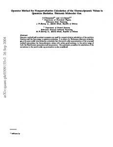
Solution The solution is based upon the qualitative description of the interlaminar stress field obtained by enforcing overall equilibrium (Pagano and Pipes, 1971) and the application of the principle of minimum complementary energy. By judiciously placing a rectangular parallelepiped element so that its x2 faces correspond with the stress-free edge and center plane of a laminate, as shown in Fig. 2, six general equations are derived from overall force and moment equilibrium considerations (Lagace and Kassapoglou, 1985):
\z+ °izdx- j 2 _ °Udx~ J2_ al2dz = 0 - j 2 _ a22dz+ ] z + a2zdx- j z _ u2zdx=0 \z+"zzdx-\z_azzdx
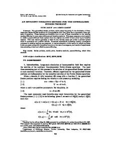
Fig. 1 Geometry for problem of a laminated plate under uniaxial loading
=0
] 2 _ "zizdz- j 2 + ozzxdx+ j z _ oaxdx-h\z+ +
Fig. 2
Free body diagram of a section of a laminate at the free edge
need for a simple, efficient, and cost-effective technique to calculate interlaminar stresses which the designer can use, especially in preliminary design stages, to avoid delaminationprone laminates. 2
Formulation
A composite laminate under uniaxial load is illustrated in Fig. 1. The out-of-plane direction is denoted by z, as opposed to x}. In order to determine the three-dimensional state of stress in the laminate, three assumptions are made. One, each ply is treated as macroscopically homogenous and is represented by its three-dimensional elastic constants. This effective modulus approach has the effect of "smearing out" the individual behavior of the fiber and matrix and is valid over distances sufficiently larger than the size of an individual fiber (0.0076 mm for typical graphite). Two, far from the free edge, the classical laminated plate theory solution is recovered and the interlaminar stresses are thus zero. Three, away from the effects of load introduction, stresses do not depend on the longitudinal direction xx. In addition to these assumptions, the stress field must satisfy several boundary conditions. One, the top and bottom surfaces of the laminate at z equal to ± h/2, where h is the total laminate thickness, are stress free. Two, the x2 faces of the laminate at x2 equal to ±b, with 2b as the total laminate width, are stress free. Three, the boundary condition in the xx direction is that there is some applied uniform traction an. Four, traction continuity must be satisfied from ply to ply. Journal of Applied Mechanics
+
aXzdxdz-