Jul 20, 2015 - [7] TIMOTHY A. DAVIS, Direct Methods for Sparse Linear Systems, Society ... [11] ALAN GEORGE, Nested dissection of a regular finite element ...
AN EFFICIENT SOLVER FOR SPARSE LINEAR SYSTEMS BASED ON RANK-STRUCTURED CHOLESKY FACTORIZATION
arXiv:1507.05593v1 [cs.NA] 20 Jul 2015
JEFFREY N. CHADWICK AND DAVID S. BINDEL Abstract. Direct factorization methods for the solution of large, sparse linear systems that arise from PDE discretizations are robust, but typically show poor time and memory scalability for large systems. In this paper, we describe an efficient sparse, rank-structured Cholesky algorithm for solution of the positive definite linear system Ax = b when A comes from a discretized partial-differential equation. Our approach combines the efficient memory access patterns of conventional supernodal Cholesky algorithms with the memory efficiency of rank-structured direct solvers. For several test problems arising from PDE discretizations, our method takes less memory than standard sparse Cholesky solvers and less wall-clock time than standard preconditioned iterations. Key words. supernodal Cholesky, preconditioners, low-rank structure, randomized algorithms AMS subject classifications. 65F05, 65F08, 65F50
1. Introduction. We consider the problem of solving a sparse linear system Ax = b
(1.1)
in which A is symmetric and positive definite (SPD). In particular, we consider the Cholesky factorization A = LLT ,
(1.2)
where L is a sparse lower triangular matrix; see [12, 9, 7]. After factoring A, one solves (1.1) by two triangular solves, at cost proportional to the number of nonzeros in L. This approach solves (1.1) exactly up to roundoff effects, and modern supernodal factorization algorithms achieve high flop rates by organizing the factorization around dense matrix kernels. The chief drawback of sparse direct methods is that the factor L may generally have many more nonzero elements than A. These fill elements limit scalability of the method in both time and memory used, particularly for problems coming from the discretization of three-dimensional PDEs, where the number of nonzeros in L typically scales as O(N 3/2 ), where N is the dimension of A. Compared to direct factorization, iterative methods for (1.1) generally cost less in memory and in time per step than direct methods, but converge slowly without a good preconditioner. Preconditioning involves a complex balance between the progress in each step and the cost of setting up and applying the preconditioner. Even for a single preconditioner type, there are usually many parameters that are optimized on a problem-by-problem basis. For this reason, packages like PETS provide interfaces to allow users to quickly experiment with different preconditioners and parameter settings [1], while commercial finite element codes often forego the potential benefits of iterative methods and simply use out-of-core direct solvers [26]. Fast direct factorization methods and preconditioned iterative solvers each use a different types of structure. A key idea behind sparse direct methods is that one can use the structure of the graph associated with A to reason about about fill in L. This graph-theoretic approach underlies many modern sparse matrix algorithms, from methods of computing fill-reducing elimination orderings to “supernodal” factorization methods organized around dense matrix operations on columns with similar nonzero structure [7]. In contrast, to solve problems arising from elliptic PDE discretization efficiently, multi-level preconditioners exploit the elliptic regularity of the underlying differential equation. Building on ideas from fast direct 1
2
JEFFREY N. CHADWICK AND DAVID S. BINDEL
solvers for integral equations [15], recent work in “data-sparse” direct solvers uses both types of structure at once, computing a structured factorization that incorporates (approximate) low-rank blocks [14, 30, 25, 28, 13]. In this paper, we describe an efficient sparse, rank-structured Cholesky algorithm for the solution of (1.1) when A comes from discretization of a PDE. Our method combines the efficient memory access patterns of conventional supernodal Cholesky algorithms with rankstructured direct solvers. Unlike prior solvers, our method works as a “black box” solver, and does not require information about an underlying PDE mesh. For several test problems arising from PDE discretizations, we show that our method takes less memory than standard sparse Cholesky codes and wall-clock time than standard preconditioners The remainder of the paper is organized as follows. In Section 2, we briefly review the standard supernodal left-looking sparse Cholesky algorithm on which our method is based. In the supernodal factorization, each supernode has an associated diagonal block storing interactions within that supernode, and an off-diagonal block for storing interactions between supernodes. In Section 3, we describe how our algorithm forms and uses low-rank approximations to the off-diagonal blocks of the supernodes, and in Section 4, we describe our approach to hierarchical compression of the diagonal blocks. We discuss some key implementation details in Section 5, and illustrate the behavior of our algorithm on several example problems in 6. Finally, in Section 7, we conclude and give potential directions for future work. 2. Background and Notation. We focus primarily on supernodal left-looking Cholesky factorization. This method has yielded implementations which make effective use of modern computing architectures to efficiently solve (1.1) [6]. 2.1. Supernodal Left-Looking Cholesky Factorization. Most sparse Cholesky codes have two phases: a fast symbolic analysis phase to compute the nonzero structure of L, and a more expensive numerical factorization phase in which the actual elements of L are computed. The symbolic analysis phase is organized around an elimination tree that encodes the structure of L: in general, lij 6= 0 precisely when there is some k such that aik 6= 0 and j is reachable from k by an elimination tree path that passes only through nodes with indices less than i. Often, the elimination tree has chains of sequentially-numbered nodes corresponding to columns with similar nonzero structure; these can be seen as supernodes in a coarsened version of the elimination tree. Supernodal factorization algorithms organize L around such supernodes, formed by collecting adjacent columns which are predicted to have similar non-zero patterns in L. Supernodal methods achieve high efficiency by storing the nonzero entries for a supernode together as a dense matrix, and by operating on that matrix with optimized kernels from the BLAS. Suppose L ∈ RN ×N is partitioned into M supernodes. Let Cj = (c : cj ≤ c < cj+1 ) refer to the column indices in supernode j, and let CO j = (c : c ≥ cj+1 ) be the list of columns occurring after supernode j. Finally, let Lj refer to the block column Lj = L(:, Cj ). Since L is lower triangular, it follows that Lj (1 : cj − 1, :) = 0. We store the matrix Lj (Cj , :) explicitly as a dense matrix and refer to this as the supernode’s diagonal block LD j . We also define Rj to be the list of nonzero rows of Lj below the diagonal block; that is, � � Rj = k ∈ CO : ∃p ∈ Cj , `k,p 6= 0 = rj1 , rj2 , . . . . (2.1) Since columns in Cj have similar non-zero patterns, we store Lj (Rj , :) as a dense matrix and refer to this as supernode j’s (compressed) off-diagonal block LO j . Left-looking algorithms such as the one implemented in [6] form block columns Lj in order from left to right. We identify the descendants Dj of supernode j as follows: Dj = {1 ≤ k < j : Rk ∩ Cj 6= ∅} ;
(2.2)
AN EFFICIENT SOLVER BASED ON RANK-STRUCTURED CHOLESKY FACTORIZATION
3
that is, supernodes from earlier in the factorization whose off-diagonal row set intersects the column set of node j. We also refer to node j as an ancestor of node k if k ∈ Dj . For convenience, we also define index lists relating rows in supernode j to rows in a the offdiagonal block LO k of a descendant supernode k: D Rk→j = (1 ≤ p ≤ |Rk | : rkp ∈ Cj ) , O Rk→j
= (1 ≤ p ≤ |Rk | :
rkp
(2.3)
∈ Rj ) .
(2.4)
D Intuitively, (2.3) helps us extract the rows of LO k that influence the contents of Lj . Similarly, O O D we use (2.4) to extract rows of Lk needed to form Lj . We will also write Rk→j to denote � � D D the index list corresponding to Rk→j in the uncompressed structure, rkp ∈ Rk : p ∈ Rk→j ,
and similarly for RO k→j . We also find it convenient to define the function scatterRows(B, R1 , R2 ), where R1 ⊆ R2 are ordered index lists, and B has |R1 | rows. This function returns a matrix with |R2 | rows by placing the contents of rows of B in the output according to the positions of entries of R1 in R2 . For example, 0 0 �� � � 1 2 1 2 (2.5) scatterRows , {3, 8} , {2, 3, 5, 8} = 0 0 . 3 4 3 4 We similarly define the functions scatterColumns(B, C1 , C2 ), and scatter(B, R1 , R2 , C1 , C2 ) which composes scatterRows and scatterColumns. Finally, we define gatherRows as a function which reverses the operation of scatterRows; e.g., if scatter(B, R1 , R2 ) = C then gatherRows(C, R2 , R1 ) = B. Forming the numerical contents of supernode j begins with assembly of a block column of the Schur complement: � � X � O D �T D D D scatter LO UD j = A(Cj , Cj ) − k Rk→j , : Lk Rk→j , : , Rk→j , Cj , Rk→j , Cj k∈Dj
UO j
= A(Rj , Cj ) −
X
scatter
�
LO k
O Rk→j ,:
�
LO k
�T D Rk→j ,: ,
RO k→j ,
Rj ,
RD k→j ,
(2.6) � Cj
k∈Dj
(2.7) O D O UD j and Uj are dense matrices with the same sizes as Lj and Lj . We note that if node k O is a descendant of node j, then Rk ∩ Cj ⊆ Rj . The Schur complement in node j is formed by first extracting dense row subsets of LO k for each descendant k, then forming the matrix products from (2.6-2.7) using dense matrix arithmetic and finally scattering the result to UD j and UO . Next, the diagonal and off-diagonal blocks of supernode j are formed as follows: j � � D LD (2.8) j = chol Uj � O D −T LO (2.9) j = Uj Lj
This procedure is summarized in Algorithm 1. 2.2. Fill-Reducing Ordering. Figure 2.1 provides an example of how a nested dissection ordering might be used on a simple two-dimensional domain, and how this ordering influences fill in the Cholesky factor of the reordered matrix.
4
JEFFREY N. CHADWICK AND DAVID S. BINDEL
Algorithm 1: factorSupernode: Computes the diagonal and off-diagonal blocks LD j and LO j for supernode j. Provided inputs are the matrix to be factored, as well as the partially constructed factor L. every supernode k ∈ Dj (node j’s descendants) is assumed to have already been factored. input : A, j, L, Dj O output: LD j , Lj 1 begin 2 // Initialize the Schur complement blocks 3 UD j ←− A(Cj , Cj ) D 4 Uj ←− A(Rj , Cj ) 5 6 7 8 9 10 11 12 13
for each k ∈ Dj do // Build dense update blocks D O D T diagUpdate ←− LO k (Rk→j , :) ∗ Lk (Rk→j , :) O O O D offDiagUpdate ←− Lk (Rk→j , :) ∗ Lk (Rk→j , :)T // Scatter updates to the Schur complement D D D UD j ←− Uj − scatter(diagUpdate, Rk→j , Cj , Rk→j , Cj ) O O O Uj ←− Uj − scatter(offDiagUpdate, Rk→j , Rj , RD k→j , Cj ) // Factor node j’s diagonal block D LD j ←− cholesky(Uj )
15
// Dense triangular solve O D −T LO j ←− Uj (Lj )
16
O return LD j , Lj
14
A
L
F IG . 2.1. Fill during nested-dissection Cholesky factorization for a 2D mesh example (left). When nodes in a mesh are ordered so that a vertex separator appears last after the subdomains it separates (right), fill in the Cholesky factor (indicated by red circles) is restricted to the diagonal blocks corresponding to interactions within each subdomain and within the separator and to off-diagonal blocks associated with subdomain-separator interactions.
3. Off-Diagonal Block Compression. In §2.1 we introduced the notion of supernodes O with dense diagonal and off-diagonal blocks LD j and Lj . In this section, we discuss the proO cess of approximating off-diagonal blocks LO j with low-rank matrices. The matrix Lj stores interactions between supernode j, and other supernodes in occurring later in the factorization. 3.1. Block Selection and Ordering. We use nested dissection [11] to construct a fillreducing ordering as originally discussed in §2.2. We choose nested dissection because the geometric structure introduced by this method yields a factor matrix L in which many dense
AN EFFICIENT SOLVER BASED ON RANK-STRUCTURED CHOLESKY FACTORIZATION
5
...
F IG . 3.1. Nested dissection is applied to a regular, two-dimensional grid. At each level, the domain is recursively subdivided by the introduction of separators. Each image in the sequence depicts a level in the recursive dissection of the domain. Separators at the same level in the nested dissection hierarchy are rendered with the same color. In the rightmost figure we see that five levels of nested dissection fully decompose this domain in to subdomains of unit size.
submatrices are amenable to low-rank approximation. We will discuss this property in more detail in §3.3. Henceforth, we will assume that the matrix A has already been symmetrically permuted using nested dissection. We expect that the interactions between large separators in the factorization will exhibit rapidly decaying rank structure (see §3.3). Therefore, we represent each “large” separator from the nested dissection hierarchy with a supernode. The off-diagonal blocks LO j associated with these supernodes describe interactions between large separators in the factor (see Figure 3.2). Standard sparse Cholesky solvers such as CHOLMOD [6] may optionally use nested dissection for reordering. However, the process of constructing supernodes used by these solvers does not guarantee a one-to-one relationship between supernodes and separators from the nested dissection ordering. In our algorithm, we choose a tolerance τO ∈ Z+ and introduce a supernode for every separator with at least τO variables. The remaining indices in our reordered matrix A are gathered in to supernodes using methods identical to [6]. 3.2. Block Compression Scheme. Consider the state of the factorization immediately prior to forming the factor contents for supernode j:
AD pre AO pre
D sym Lpre AD sym = O j Lpre AO Apost j
I 0
I
LD pre LO pre
T UD j UO j
Upost
(3.1)
Here pre and post refer to the sets of columns occurring before and after supernode j, respectively. Note that the Schur complement Upost is never formed explicitly since we only form Schur complements one supernode at a time. We also note that given the definition of Uj and Lj , it is necessary to apply the scatter operator to these matrices to make (3.1) valid, but this has been omitted here for brevity. Following factorization of node j, we have:
AD pre
AO pre
D Lpre sym sym AD sym = j LO pre AO A post j
LD j LO j
LD pre
LO pre
I
T LD j LO j
e post U
(3.2)
where e post = Upost − LO LO U j j
�T
.
e post must also be positive definite. Assuming A is positive definite, U
(3.3)
6
JEFFREY N. CHADWICK AND DAVID S. BINDEL
j1
j2
j3
j1
j2
j3
F IG . 3.2. Consider the two-dimensional grid on the left, decomposed via nested dissection (see Figure 3.1). If we set τO = 5, then the three largest separators will be identified as supernodes (labelled j1 , j2 and j3 ). The O resulting matrix structure is shown on the right. The off-diagonal blocks LO j1 and Lj2 are shown in white and describe interactions between separator j3 and separators j1 and j2 , respectively. In the domain picture on the left we see that, due to the way these separators intersect geometrically, these interactions tend to mostly occur over large distances. This justifies the use of low-rank matrices to approximate these interactions. The parts of the factor for which we do not apply any compression are shown in gray. These blocks can be evaluated either using the standard supernodal factorization algorithm, or using the interior blocks approach discussed in §5.1.
T If we approximate the off-diagonal part of supernode j with a low-rank matrix – LO j ≈ VU – then the Schur complement in (3.3) is approximated by
Upost = Upost − VUT UVT .
(3.4)
We choose V and U using a method similar to [23] so that this modified Schur complement (3.4) is guaranteed to remain positive definite. Namely, we choose U to have orthonormal O O columns and V to be the projection of LO j on to this basis; V = Lj U. We can write Lj = T T [V V][U U] where U is a (non-unique) matrix with orthonormal columns, U U = 0, and V = LO j U. Given these properties, we can rewrite (3.3) as e post = Upost − VVT − V VT U
(3.5)
Upost = Upost − VVT
(3.6)
and (3.4) as
T
e post + V V . =U
(3.7)
e post is positive definite and V VT is positive semi-definite, it follows from (3.7) that Since U Upost remains positive definite under this approximation. 3.3. Low-Rank Structure. Recall from §3.1 that we use nested dissection to reduce fill and represent large separators as supernodes in the factorization. Nested dissection orderings are built entirely based on A’s graph structure. However, in problems defined on physical domains (say, discretizations of partial differential equations on two- or three-dimensional domains) separators also have a convenient geometric interpretation. In these problems, separators are geometric regions which bisect subdomains of the original problem domain (see Figures 3.1 and 3.2). For example, in many three-dimensional problems the nested dissection
7
AN EFFICIENT SOLVER BASED ON RANK-STRUCTURED CHOLESKY FACTORIZATION
separators are surfaces which cut the domain in to disjoint pieces. Given a partial factorization of a matrix A, the remaining Schur complement U behaves like a discretization of a boundary integral equation [5]. For many problems, these discretizations will yield smooth coefficients for matrix indices which are geometrically distant from each other in the original problem domain. The structure of separators produced by nested dissection tends to ensure that the interactions between pairs of large separators occur mostly over large distances, with only a handful of “near-field” interactions (see Figure 3.2). If supernode j corresponds to a large separator and UO j is this node’s off-diagonal block in the Schur complement, then we O expect that Uj should have rapidly decaying rank structure due to the property discussed O above. As such, UO j (and, likewise, Lj ) admits a low-rank approximation. Therefore, we compress the off-diagonal blocks in supernodes/separators which are sufficiently large (larger than τO ). We use the following notation for this low-rank approximation: T LO j ≈ V j Uj
where Vj ∈ R|Rj |×q , Uj ∈ R|Cj |×q
and
q � |Rj |, |Cj |
(3.8)
Algorithm 2: offDiagonalMultiply: Computes the product B = LO j G given some in|Cj |×r put matrix G ∈ R , r > 0. The function diagonalSolve(j, X, transpose) applies the inverse of LD j to the input matrix. If transpose is set to true, then diagonalSolve −T forms the product (LD X instead. See §4 and Algorithm 4 for a detailed descripj ) tion of diagonalSolve. input : A, j, L, Dj , G output: B = LO j G 1 begin 2 // Apply node j’s diagonal inverse to the input 3 G ←− diagonalSolve(j, G, transpose = true) 4 5
// Multiply by the desired block from A W ←− A(Rj , Cj )G
6
for each k ∈ Dj do // Extract the required sub-matrix from G Gsub ←− gatherRows(G, Cj , RD k→j )
7 8
10
// Form the needed product with two multiplications h iT D Gsub T ←− LO k (Rk→j , :)
11
O T ←− LO k (Rk→j , :)T
9
12 13 14
// Scatter result to the output matrix W ←− W − scatterRows(T, RO k→j , Rj ) return W
3.4. Compression Algorithm. Next we discuss our approach for forming the low-rank T approximation LO j ≈ Vj Uj . Our compression strategy must satisfy two requirements: 1. The off-diagonal block LO j may be expensive to construct and store. Therefore, we wish to build Vj , Uj without explicitly constructing LO j . 2. The original supernode factorization procedure presented in algorithm 1 makes effective use of dense matrix arithmetic, allowing for very efficient implementations [6]. Our compression algorithm should preserve this property.
8
JEFFREY N. CHADWICK AND DAVID S. BINDEL
To satisfy these requirements, we use randomized low-rank approximation algorithms [24, 16]. Similar randomized methods have been used previously in rank-structured sparse solvers [10, 29]. The key insight behind these randomized algorithms is that a “good” rank-q approximation to a matrix B can be found by considering products of the form BG, where G is a randomly generated matrix with q + p columns and p > 0 is a small oversampling parameter (typically p ≈ 5 − 10 is suitable). In this case, we consider a rank-q approximation to be good if it is close (in the 2-norm) to the best rank-q approximation provided by B’s singular value decomposition (SVD). If the singular values of B decay slowly, then obtaining such an approximation may require us to instead form products of the form C = (BBT )s BG, where s ≥ 0 is a small number of power iterations. The theory behind these methods states that C provides a column basis for a low-rank approximation of B which is close to optimal. Moreover, constructing C only requires a small number of matrix multiplications involving B and BT . Therefore, requirement 1 above is satisfied. We can also perform these multiplications in a way that leverages dense matrix arithmetic similar to Algorithm 1, satisfying requirement 2. Algorithm 2 efficiently forums products LO j G for an arbitrary dense matrix G. As dis�T cussed earlier, we also require products of the form LO G. These products are formed j by the function offDiagonalMultiplyTranspose. This function has similar structure fo Algorithm 2. Finally, Algorithm 3 uses the offDiagonalMultiply and offDiagonalMultiplyTranspose T functions to form a low-rank approximation LO j ≈ Vj Uj for node j’s off-diagonal block, where Uj is chosen to have orthonormal columns (as discussed in §3.2). We note that Algorithm 2 assumes the matrix LO k is stored explicitly for all descendants k ∈ Dj . In practice, T some of these blocks may also have been assigned low-rank representations LO k ≈ V k Uk . If this is the case, then we replace lines 10-11 in Algorithm 2 with Uprod ←− UTk Uk � �T D T ←− Vk (Rk→j , :) Gsub T ←− Uprod T O T ←− Vk (Rk→j , :)T.
(3.9)
4. Diagonal Block Compression. Section §3 discussed the process of constructing a sparse Cholesky factorization in which off-diagonal interactions between large separators are approximated with low-rank matrices. In large, three-dimensional problems, larger separators may include thousands to tens of thousands of variables. For these problems, the compression scheme from §3 can provide a significant reduction in both memory usage over standard factorizations, while still providing a factor that serves as an excellent preconditioner. However, if supernode j is large, then building the dense diagonal matrix LD j may also require significant computation and storage. In this section, we discuss an approach to compressing diagonal blocks LD j . 4.1. Low-Rank Structure. In §3 we saw that low-rank behavior in off-diagonal blocks LO j is exposed by the geometric structure of nested dissection. We can reorder variables within a separator to expose similar low-rank structure within diagonal blocks LD j . Since all columns in a given supernode are treated as having the same fill pattern, we are can perform this reordering without affecting accuracy, memory usage, or computation time. Consider the top-level separator shown in figure 3.1. Suppose that the indices of vertices in this separator are ordered sequentially from top to bottom and that the 9×9 diagonal block for this separator is written as a 2 × 2 block matrix (assume, without loss of generality, that the first block
AN EFFICIENT SOLVER BASED ON RANK-STRUCTURED CHOLESKY FACTORIZATION
9
Algorithm 3: approximateOffDiagonal: Builds a low-rank approximation LO j ≈ Vj UTj for node j’s off-diagonal block. This algorithm assumes that node j’s diagonal block has already been factored. The function randomMatrix(m, n) generates an m × n matrix whose entries are drawn from a Gaussian distribution with mean 0 and unit variance. The function makeOrthonormal returns an orthonormal basis for the column space of its input matrix. This can be accomplished by means of – for example – a QR factorization. input : A, j, L, Dj , off-diagonal rank sj , number of power iterations q T output: Vj , Uj such that LO j ≈ V j Uj 1 begin 2 // Initialize a random matrix 3 G ←− randomMatrix(|Rj |, sj ) 4 5 6 7 8 9
// Implicitly form the product LO j G G ←− offDiagonalMultiplyTranspose(A, j, L, Dj , G) // Run additional power iterations for i = 1 to q do G ←− offDiagonalMultiply(A, j, L, Dj , G) G ←− offDiagonalMultiplyTranspose(A, j, L, Dj , G)
11
// Extract an orthonormal row basis for LO j Uj ←− makeOrthonormal(G)
12 13
// Compute Vj by projecting on to Uj Vj ←− offDiagonalMultiply(A, j, L, Dj , Uj )
14
return Vj , Uj
10
row/column has four entries, and that the second has five): � � L11 0 LD = j L21 L22 As a result of the ordering discussed above, L21 stores interactions between vertices in the top half of the separator with vertices in the bottom half. As we discussed in §3.3, the spatial separation between these groups of variables suggests that L21 can be approximated with a low-rank matrix L21 ≈ VUT . We can apply this argument recursively to L11 and L22 to achieve further compression. The example above assumes that the rows/columns of LD j are ordered such that offD diagonal blocks of Lj exhibit low-rank structure. Finding such an ordering is straightforward when A comes from a PDE discretization on a regular mesh like the one pictured in Figure 3.1. However, obtaining a suitable ordering for general, three-dimensional problems on irregular domains is nontrivial. Recall from §3.3 that separators in the nested dissection hierarchy are geometric regions partition the original problem domain. In three dimensions, we intuitively expect these separators to look like two-dimensional surfaces inside of the original problem domain. Our solver exposes low-rank structure in LD j by reordering indices within separators so that off-diagonal blocks in LD describe interactions between spatially separated pieces of the separator region. j We begin by assigning a three-dimensional position xi : i ∈ Cj to each index associated with supernode/separator j. There are many techniques for spatially partitioning the positions xi .
10
JEFFREY N. CHADWICK AND DAVID S. BINDEL
Cj
I1 ∩ I2
I1
AD j
I3 ∩ I4
I2
I3
AD j (I1 , I1 )
sym.
D Aj (I2 , I1 ) AD j (I2 , I2 ) −→ AD j (I3 ∪ I4 , I1 ∪ I2 )
I4
sym. AD j (I3 , I3 )
sym.
AD j (I4 , I3 )
AD j (I4 , I4 )
F IG . 4.1. We recursively partition supernode j’s variable indices Cj resulting in the tree structure shown on the left (assuming two levels of partitioning in this case). We permute the indices in Cj so that, following this permutation, the index blocks associated with leaves in this tree structure appear sequentially along the diagonal of D AD j . The resulting permutation to Aj for this two-level example is shown on the right.
Currently, we use a simple axis-based splitting scheme. We partition the positions xi in to two subsets by sorting them along the longest bounding box axis of the set {xi : i ∈ Cj } and splitting this sorted list in to two equal-sized pieces. This process is applied recursively until the separator has been partitioned in to subdomains with at most τD variables. The paramter τD is chosen in advance as the size of the largest diagonal block that we wish to represent explicitly in the factor matrix. We use this partitioning to reorder the indices within a supernode in a way that exposes low-rank structure. See Figure 4.1 for an explanation of how this permutation is built. Using the two-level partitioning example shown this figure, we label blocks of the diagonal factor block LD j as follows: LD j
LD j,1
0
D Lj,2 LD j,3 = LD j,4
0 LD j,5
0
LD j,6
LD j,7
.
(4.1)
Blocks are numbered in the order in which they must be formed during factorization (intuitively, top to bottom and left to right). In this 4 × 4 example, LD j is be approximated as follows: LD 0 j,1 0 D D T D V (U ) L j,2 j,2 j,3 D . Lj ≈ (4.2) D L 0 j,5 D D T Vj,4 (Uj,4 ) D T D Vj,6 (UD ) L j,6 j,7 D D For block s in this matrix, let Rj,s and Cj,s be the set of rows and columns over which block s D D D D D D is defined, relative to Lj . That is, Lj (Rj,s , Cj,s ) = LD j,s . Similarly, let Rj,s and Cj,s refer to D D the same row and column sets, but relative to the entire factor L, so that L(Rj,s , Cj,s ) = LD j,s . In summary, we permute the original matrix A in two main steps. The first is fill-reducing ordering using nested dissection. As we noted in §3, this step exposes low-rank structure in certain off-diagonal submatrices of L, allowing for compression. The second stage of this permutation consists of reordering indices within certain supernodes formed in the first stage – namly, those associated with large separators. This does not alter the sparsity of L, but does allow us to compress certain off-diagonal submatrices of these large diagonal blocks.
AN EFFICIENT SOLVER BASED ON RANK-STRUCTURED CHOLESKY FACTORIZATION
11
LD j,1 LD j,3 LD j,2
LD j,5
LD j,4
LD j,7 LD j,6
Dj
F IG . 4.2. Block row of a factor in which node j (on the right) has a hierarchically compressed diagonal matrix LD j with structure given by (4.1). Compressed matrices are indicated with a dashed border. Consider the compressed block LD j,6 . When forming products with this matrix (for the purpose of compression), we require contributions from all columns of L with non-zeros in the region highlighted with a thick black border. Observe that this includes D contributions from descendents Dj , as well as other compressed blocks in LD j . In this case, Lj,6 depends on three of node j’s descendents, as well as LD . j,4
4.2. Compression Algorithm. Next, we turn to compression of off-diagonal blocks within a diagonal matrix LD j . As in the compression methods discussed in §3, we use randomized methods to construct low-rank matrix approximations. First, we define the diagonalSolve function, originally introduced in Algorithm 2. We consider a slight variation on this function, in which the index s of a block from LD j is provided as an argument. Invoking this function with argument s solves a system of equations using the smallest diagonal sub-block D of LD j containing Lj,s . Using (4.2) as an example, calling diagonalSolve with s = 2 would solve a system using the inverse of LD 0 j,1 . (4.3) �T D Vj,2 UD LD j,2 j,3 For brevity, calling diagonalSolve with no “s” argument (as in Algorithm 2) solves systems using the entire matrix LD j . This process is summarized in Algorithm 4. Throughout the algorithms discussed in this section, we treat the indices s of blocks in LD j as the labels of nodes in an in-order traversal of a complete binary tree. When we refer to a child or parent of s, we mean the in-order index of the node which is the child or parent of the node with in-order index s in this tree. For example, if LD j has 7 blocks (as in (4.1)), then s = 4 is the root of this tree and has left and right children with indices 3 and 6, respectively. We will now use the diagonalSolve function to build an algorithm for compressing an D off-diagonal block LD j,s . As before, we multiply Lj,s with random matrices without explicitly D constructing Lj,s As in §3.4, these operations depend on the contents of node j’s descendants Dj . In addition, we may need to consider contributions from previously compressed blocks within LD j . See Figure 4.2 for a visual representation of this dependence. The diagonalMultiply algorithm (Algorithm 5) provides the details of this procedure.
12
JEFFREY N. CHADWICK AND DAVID S. BINDEL
Algorithm 4: diagonalSolve: Solves a system of equations using the submatrix of LD j rooted at block s in LD j ’s hierarchical structure. 1 2 3 4 5 6 7 8 9 10 11 12 13 14 15 16 17 18 19 20 21 22 23 24 25
input : j, G, transpose, s begin // Leaf nodes correspond to dense diagonal blocks if Node s is a leaf then if transpose then −T return (LD G j,s ) else −1 return (LD G j,s ) else // Partition G into two parts D |, :) G1 = G(1 : |Cj,s D G2 = G(|Cj,s | + 1 : end, :) // Child blocks of s s1 = left in-order child of s s2 = right in-order child of s if transpose then // Backward substitution G1 ←− diagonalSolve(j, G1 , transpose, s1 ) � D T G2 ←− G2 − Vj,s (UD j,s ) G1 G2 ←− diagonalSolve(j, G2 , transpose, s2 ) else // G2 G1 G1
Forward substitution ←− diagonalSolve(j, G2 , transpose , s2 ) � D T ←− G1 − UD (V ) G 2 j,s j,s ←− diagonalSolve(j, G1 , transpose, s1 ) � � G1 return G2
Lines 7-15 in this algorithm resemble the descendant multiplication from Algorithm 2. Lines 17-35 compute contributions from other blocks inside of LD j . As before, we also require the algorithm diagonalMultiplyTranspose. This algorithm has a similar structure to Algorithm 5 With these two functions, we define a function approximateDiagonalBlock which computes a low-rank representation of LD j,s given some prescribed rank. The structure of this algorithm is not given here since it is nearly identical to Algorithm 3. Finally, we turn to the question of how to construct dense diagonal blocks within LD j . As in Algorithm 1, lines 7 & 10, we will consider update matrices built from off-diagonal blocks in node j’s descendants. In addition, we will need to consider contributions from previously computed low-rank blocks in LD j . The details of this process are given in Algorithm 6. Given algorithms for forming diagonal and off-diagonal blocks in LD j , building this matrix follows a straight forward process of iterating over the blocks of LD j in increasing order s = 1, 2, . . .. At each iteration, we either form the diagonal block LD j,s or a low-rank deD T composition Vj,s (UD ) . Finally, we note that, unlike the off-diagonal compression scheme j,s
AN EFFICIENT SOLVER BASED ON RANK-STRUCTURED CHOLESKY FACTORIZATION
13
presented in §3.2, forming diagonal blocks and approximate off-diagonals in this order does not guarantee that positive definiteness is maintained throughout the factorization. We discuss our simple method for addressing this issue in §5.3. 4.3. Choosing Diagonal Block Coordinates. In §4.1-4.2 we assumed that indices within LD could be reordered to expose low-rank structure in off-diagonal blocks LD j j,s . As we discussed in §4.1, this is accomplished by assigning spatial coordinates to degrees of freedom D within LD j . Indices are reordered such that off-diagonal blocks in Lj describe interactions between spatially separated “pieces” of the separator with which node j is associated. However, we have not yet discussed how these spatial coordinates are determined. In many applications, this information can be determined from the underlying PDE. For example, in §6 we discuss several model problems implemented in the Deal.II finite element library. For these problems, spatial coordinates are determined directly from node positions in a finite element mesh. Unfortunately, this information may not be readily available in some cases. In the interest of building a general, algebraic preconditioner, we wish to also consider cases in which spatial coordinates for system degrees of freedom are not provided. Research in the area of graph visualization has yielded a variety of methods for building visually appealing drawings of graphs [22, 4]. Given a sparse matrix A, we can infer geometric positions for matrix indices by applying these algorithms to the graph structure implied A’s non-zero pattern. In this work, we appeal to spectral graph drawing algorithms, which build positions based on the spectral properties of certain matrices associated with the original system matrix A. In particular, we consider A’s Graph Laplacian L, defined as follows: −1 if i 6= j, Aij 6= 0 0 if i 6= j, Aij = 0 (4.4) Lij = |{k 6= i : Aik 6= 0}| if i = j We evaluate the three lowest-order eigenvectors v1 , v2 , v3 of L and associate the threedimensional position [v1i v2i v3i ] with matrix index i. We find that low-accuracy approximations of these eigenvectors suffice, and we evaluate these eigenvectors using Arnoldi iteration. See §6 for further discussion on the cost of constructing these positions. 5. Additional Optimizations and Implementation Details. In this section we discuss additional optimizations for further storage reduction in our algorithm, as well as key implementation details. 5.1. Interior Blocks. The algorithm discussed in §3-4 builds a sparse Cholesky factor on a matrix permuted with a nested dissection ordering. Separators in the nested dissection hierarchy that are sufficiently large – that is, having more than τO variables – are identified as supernodes in a supernodal Cholesky factorization and the diagonal and off-diagonal blocks for these supernodes are compressed. Supernodes with fewer than τO variables may be factored using the standard supernodal sparse Cholesky algorithm; however, in this section we present a more memory-efficient method for handling these uncompressed blocks. The collection of compressed separators discussed above partitions the domain in to a collection of mutually disjoint subdomains (see Figure 5.1 – left side), which we refer to as interior blocks. This remains true even for non-physical problems in which the “domain” is the graph defined by the sparsity pattern of the matrix to be factored. The nested dissection permutation guarantees that the variables in an interior block appear in a contiguous block in the reordered matrix (see Figure 5.1 – right side). As such, an interior block can be represented by a sequential list of supernode indices. For interior block i (numbered in the order in which it appears in the reordered matrix), we use the notation Bi to denote the list of supernode indices comprising the block. The column list CBi and off-diagonal row pattern RBi
14
JEFFREY N. CHADWICK AND DAVID S. BINDEL
B2
B4
j1
j2
B1
B3 j3
B1
B2
j1
B3
B4
j2
j3
F IG . 5.1. As in Figure 3.2, we apply nested dissection to a two-dimensional grid and set τO = 5. The separators with 5 or more variables partition this domain in to four disjoint subdomains, which we label as interior blocks B1,...,4 . These four blocks are shown as regions surrounded by a dashed line in the left image. The block structure in L resulting from this partitioning is shown on the right. As before, solid white blocks in this matrix denote off-diagonal blocks LO j for which we apply compression according to the methods in §3. Dashed white blocks denote the off-diagonals of interior blocks B1,...,4 . These blocks are not stored explicitly. We do, however, store the diagonal components of interior blocks explicitly, and these entries are evaluated using standard, supernodal Cholesky factorization restricted to the interior block subdomain.
associated with interior block i are defined as follows: [ [ CBi = Cj RBi = Rj \ CBi j∈Bi
(5.1)
j∈Bi
The matrices L(CBi , CBi ) and L(RBi , CBi ) are the diagonal and off-diagonal factor blocks for interior block i (the dashed/white and shaded matrix blocks in Figure 5.1, respectively). Indices within interior block i are reordered via nested dissection to guarantee that L(CBi , CBi ) is as sparse as possible. However, for our purposes we can think of interior blocks as representing the “bottom” level of the nested dissection hierarchy. When building a Cholesky factorization, blocks in a nested dissection hierarchy only depend on blocks from lower levels in this hierarchy. Therefore, the factor contents for interior block i are evaluated as follows: L(CBi , CBi ) = chol(A(CBi , CBi ))
(5.2)
L(RBi , CBi ) = A(RBi , CBi )L(CBi , CBi )−T
(5.3)
We compute L(CBi , CBi ) using a standard, uncompressed supernodal factorization. The matrix L(RBi , CBi ) only stores interactions between the variables of interior block i and supernodes compressed using the methods of §3-4 (see Figure 5.1). As a result, L(RBi , CBi ) may have many non-zero entries, making it expensive to store explicitly. Fortunately, we can still approximately factor A without ever explicitly forming the block L(RBi , CBi ). In the standard supernodal factorization (Algorithm 1), we explicitly form the Schur complement matrix for each supernode. Here, L(RBi , CBi ) must be stored explicitly because it is required when running Algorithm 1 on ancestors of nodes in interior block i. The key insight of our approach is that our factorization algorithm only uses L(RBi , CBi ) in places: 1. We explicitly build Schur complements for small diagonal blocks with fewer than τD rows/columns. This may depend on contributions from L(RBi , CBi ).
AN EFFICIENT SOLVER BASED ON RANK-STRUCTURED CHOLESKY FACTORIZATION
15
2. We must be able to form products of the form L(RBi , CBi )G and L(RBi , CBi )T G where G is an arbitrary dense matrix. These products are required by Algorithms 2 and 5. Forming the diagonal blocks referred to in the first requirement only necessitates the formation of a sub-block of L(RBi , CBi ) with at most τD rows (see Algorithm 6, line 8). This sub-block is needed exactly once for the formation of a diagonal block. We can form small sub-blocks of L(RBi , CBi ) as needed to build diagonal block Schur complements, then discard them immediately afterwards. We also observe that the products from the second requirement listed above can be formed without explicitly forming any part of L(RBi , CBi ). Suppose that we wish to compress blocks in supernode j, and that this node has some descendents in interior block i; that is, Dj ∩ Bi 6= ∅. Forming the product LO j G for some dense matrix G can be done by considering each descendent in Dj individually, as is done in Algorithm 2. Alternately, we can consider all of the descendents in interior block i simultaneously. To do this, we first recall that LBi = L(CBi , CBi ) is computed explicitly using sparse supernodal factorization, meaning that its inverse can be applied quickly. It follows from Algorithm 1 that interior block i’s contribution to the Schur complement UO j is given by L(Rj , CBi )L(Cj , CBi )T . We can use (5.2-5.3) to express the two matrices involved in (5.4) as �−T �−T L(Rj , CBi ) = A(Rj , CBi ) LBi L(Cj , CBi ) = A(Cj , CBi ) LBi
(5.4)
(5.5)
Finally, we can use (5.5) to write the product of (5.4) and an arbitrary dense matrix G (as required by Algorithm 2) as h �−T h B �−1 � �ii Li A(Cj , CBi )T G L(Rj , CBi )L(Cj , CBi )T G = A(Rj , CBi ) LBi (5.6) As suggested by the parenthesis in (5.6), this product is the result of multiplying a sparse matrix with G, followed by two sparse triangular solves involving LBi , followed by another multiplication with a sparse matrix. Since each of these operations can be carried out efficiently, this provides an effective method for forming the matrix products required by Algorithm 2 without having to explicitly store blocks of the form L(RBi , CBi ). A similar method can be used to form products with blocks LD j,s by replacing Rj and Cj in (5.6) (see Algorithm 5) D with RD and C , respectively. j,s j,s While the optimizations discussed here have the potential to significantly reduce storage requirements, this comes at the cost of somewhat more expensive factorization and triangular solves. We provide concrete examples of this time-memory tradeoff in §6.3. 5.2. Estimating Rank. Up until now, we have assumed when building a low-rank approximations to blocks in L that the desired rank for each block is known a priori. In this section, we discuss how block ranks are chosen. We use our approximate rank-structured Cholesky factor as a preconditioner for the Preconditioned Conjugate Gradient method. Therefore, we are also free to use simple heuristics to determine block ranks, with the understanding that the accuracy with which we approximate blocks will influence the effectiveness of our preconditioner. In principle, we could adaptively approximate blocks up to a certain tolerance (see, e.g., [24, 16]); however, our experiments showed that the additional cost of adaptive approximation outweighed the improved accuracy of preconditioners built with this method. Instead, we use a simple heuristic function depending only on the number of rows and columns in the block to be approximated. In particular, we assign the following rank to a block B ∈ Rm×n : √ (5.7) rank(B) = α k log2 (k) + p
16
JEFFREY N. CHADWICK AND DAVID S. BINDEL
F IG . 5.2. Interaction between two square separators with grid-based topology. Assuming that each separator has k variables, then √ the number of variables immediately adjacent to each other in the interaction between these two separators is k.
where k = min(m, n) and p is a small oversampling parameter. To provide a brief, intuitive explanation as to why this function was chosen, we consider the interaction between two separators in 3D space. Suppose that the separators take the shape of regular, square, twodimensional grids intersecting at a right-angle (see Figure 5.2). This may be the case in, for instance, a PDE discretized on a regular, three-dimensional finite difference grid. Assuming √ that each separator has k variables, there are k in each separator which are immediately √ adjacent to the other separator. It is for this reason that we include a term proportional to k in (5.7). We also scale rank(B) by log2 (k) since we empirically observe better preconditioning behavior when larger ranks are used to approximate larger blocks from L. In practice, we also use two different constants in (5.7) – αD and αO – which determine ranks during diagonal and off-diagonal compression, respectively. 5.3. Avoiding Indefinite Factorizations. As discussed originally in §4.2, our scheme for compressing diagonal blocks LD j does not provide a guarantee that Schur complements formed during the factorization will remain positive definite. This could result in our factorization algorithm failing for certain inputs. Fortunately, the argument in §3.2 guarantees that in the absence of compression of diagonal blocks LD j , all Schur complements remain positive definite. This implies that we can avoid the indefinite Schur complements by approximating diagonal blocks with sufficient accuracy. In practice, we address this issue by adapting the diagonal compression parameter αD in the event that an indefinite diagonal matrix is encountered during factorization. Specifically, we initialize αD = 0.5 and if factorization fails due to an indefinite matrix, we increase this constant αD ←− 1.25αD and restart the factorization process. This strategry increases the accuracy with which diagonal blocks are approximated until factorization is successful. 6. Results. We have applied the method described in this paper to a number of sample problems. In §6.1 we demonstrate the behavior of our solver on a challenging nonlinear elasticity problem. When applied to the linear systems arising in this problem, our solver provides significant performance improvements over a variety of standard solvers. In §6.2, we discuss the behavior of our solver on a variety of other sample problems. We consider
AN EFFICIENT SOLVER BASED ON RANK-STRUCTURED CHOLESKY FACTORIZATION
17
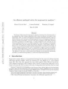
both standard examples implemented using the deal.II finite element analysis library [2, 3] and examples taken from the University of Florida sparse matrix collection [8]. While the performance differences between our solver and standard direct and iterative solvers are less dramatic in these examples, these results demonstrate the robustness of our solver. 6.1. An Example: A Nonlinear Elasticity Problem. In this section, we discuss an example that illustrates the behavior of our current solver. While we have tested our solver on numerous problems, the problem described here poses particular difficulty for standard iterative methods. As such, it is an ideal candidate for a hybrid approach such as ours which leverages the reliability of direct solvers with the low memory overhead of iterative methods. We evaluate our problem using a benchmark problem taken from [27] based on a standard example from the deal.II finite element analysis library [3, 2]. This simulation models quasistatic loading of a nearly-incompressible, hyperelastic block under compression. The code applies a force incrementally over two load steps; at each load step, a nonlinear system of equations is solved to determine the resulting deformation of the block. The nonlinear system is solved by a Newton iteration, and we evaluate the performance of our solver for solving the sequence of linear systems that arise during this process. Because this problem is nearly incompressible, standard displacementbased elements would be prone to locking. Consequently, our test problem uses a mixed formulation with explicit pressure and dilation field variables in addition to the displacement fields. We F IG . 6.1. High-resolution (N = 80), elastic block under consider two versions of this problem – compression. Our sparse rank-structured preconditioner was henceforth referred to as the p = 1 and used to compute the deformations seen here. p = 2 problems. In the p = 1 problem, displacements are discretized with continuous linear Lagrange brick elements, while pressure and dilation are discretized using discontinuous piecewise constant functions. The p = 2 problem discretizes displacements with quadratic elements and uses discontinuous linear elements for pressure and dilation. All variables are discretized on an N × N × N element grid. In all problem instances, the pressure and dilation variables are condensed out prior to the linear solve, so the system we solve involves only displacement variables. 6.1.1. Comparison to Standard Iterative Solvers. We have solved the benchmark problem with the preconditioned conjugate gradient (PCG) iteration using our rank-structured Cholesky preconditioner and several other preconditioners provided in Trilinos [17, 20, 21, 19, 18], a library of high-performance solvers developed primarily at Sandia national labs. Our code consistently out-performed a Jacobi preconditioner, an incomplete Cholesky (ICC) preconditioner, and a multi-level (ML) preconditioner in both iteration counts and wall clock time (Figure 6.2(a)–6.2(b)). Our timing results are summarized in Table 6.1. All results reported in this section were generated on an 8-core Intel Xeon X5570 workstation with 48GB of memory running Ubuntu 12.04, with LAPACK and BLAS implementations provided by the Intel Math Kernel Library version 11.0. We use the preconditioned conjugate gradient (PCG) implementation provided by AztecOO for all tests. All linear systems were solved to a relative `2 residual error threshold of 10−5 . At this accuracy level, the
18
101
101
100
100
10−1 10−2
Jacobi
10−3
10−1 10−2 10−3 ICC
10−4
10−4 ML 10−5
Relative residual
Relative residual
JEFFREY N. CHADWICK AND DAVID S. BINDEL
RSC 0
ICC 5
RSC 0
10
Iterations
Jacobi
10−5
·103
ML 0.5 Seconds
1 ·103
F IG . 6.2. PCG convergence for the first linear solve in the p = 1 benchmark problem with N = 50. Jacobi, ICC, ML and RSC refer to solves preconditioned with Jacobi, incomplete Cholesky (IFPACK), multigrid and rankstructured Cholesky (our solver) preconditioners, respectively. Convergence curves relative to wall clock time start at t > 0 due to time required to construct the preconditioner.
nonlinear iteration required 14–15 linear solve steps to converge (as compared to 12 linear solves for a standard Cholesky solver). Due to the time required to solve linear systems using the standard preconditioners, we only ran these example for N ≤ 50. For the rank-structured Cholesky solver, we ran examples up to N ≤ 80. We observe the following properties for the different preconditioners for this problem: Jacobi: The Jacobi preconditioner (diagonal preconditioner) is simple, but it usually only modestly accelerates convergence. When solving the p = 1 problem, more iterations are required to converge with the Jacobi preconditioner than with more sophisticated preconditioners. However, each iteration is so cheap that this process requires less wall clock time than solves performed with other standard preconditioners. Meanwhile, in the p = 2 problem, the number of iterations required when using a Jacobi preconditioner grows considerably, making other standard preconditioners more competitive. ICC: We timed the PCG iteration using incomplete Cholesky (ICC) preconditioners implemented in both IFPACK and AztecOO. As with most incomplete factorization codes, these solvers require several parameters, including the level of fill allowed in the factorization, drop tolerances dictating which matrix entries should be discarded, and parameters controlling perturbations to the matrix’s diagonal. The latter are required to avoid poorly conditioned factorizations since solvers based on incomplete factorizations appear to encounter severe conditioning issues when applied to this problem. In general, “good” parameter choices depend on the problem. We chose parameters for this problem based on experiments with a small problem instance (e.g., N = 20 for the p = 1 problem). When solving the p = 1 problem, even with the tuned parameters, we require almost as many iterations with IFPACK’s ICC preconditioner as with the much simpler Jacobi preconditioner. Moreover, the incomplete Cholesky preconditioner costs more than applying the Jacobi preconditioner, so the overall time to solve the linear systems is actually larger in this case. Meanwhile, we find that Aztec’s ICC preconditioner is unable to make any progress towards convergence in the
101
101
100
100
10−1 10−2
Jacobi
10−3
ML
10−2 10−3
10−5
RSCICC 0
5
10
Iterations
15 ·103
19
10−1
ML
10−4
10−4 10−5
Relative residual
Relative residual
AN EFFICIENT SOLVER BASED ON RANK-STRUCTURED CHOLESKY FACTORIZATION
ICC RSC 0
Jacobi 5 Seconds
10 ·103
F IG . 6.3. PCG convergence for the first linear solve in the p = 2 benchmark problem with N = 35 (see the caption for Figure 6.2(a)-6.2(b)). Note that the Jacobi solve was run to convergence: the left plot is truncated for clarity.
p = 1 problem. We observe the opposite behavior in the p = 2 problem. Specifically, IFPACK’s ICC preconditioner makes no progress towards convergence, whereas the AztecOO preconditioner performs reasonably well (but still significantly slower than our rank structured solver). In fact, while IFPACK’s ICC solver was the least effective standard solver (in terms of wall clock time) applied to the p = 1 problem, AztecOO’s ICC solver was the most effective standard solver applied to the p = 2 problem. This phenomenon provides further evidence of the difficulty associated with choosing an effective preconditioner for a given problem. ML: While multigrid preconditioners perform well on many problems, on our benchmark we see relatively poor convergence and long solve times. We use an algebraic multigrid preconditioner that solves the problem at its coarsest level using a direct solver provided by Amesos. The next coarsest level applies a symmetric Gauss-Seidel smoother over several sweeps (4 in this case). Finer levels use a degree-2 Chebyshev polynomial smoother. These parameters were chosen based on good convergence behavior on a small problem instance (e.g., N = 20 for the p = 1 problem). When solving the p = 1 problem, this solver requires significantly fewer iterations than the Jacobi or incomplete Cholesky solvers; but because applying the preconditioner is relatively expensive, it takes about as long to solve with the multigrid preconditioner as with a Jacobi preconditioner. When applied to the p = 2 problem, the multigrid preconditioner requires significantly fewer iterations than the Jacobi solver, but many more than the Aztec00 incomplete Cholesky solver. As a result, this solver is the least effective standard solver that we tested on the p = 2 problem. We also note here that multigrid frameworks such as the one provided by ML require tuning a wide variety of parameters (some of which are discussed above). In some cases, tuning problem-specific parameters to achieve good convergence behavior may outweigh the cost of solving the problem with a simpler method. Rank-Structured Cholesky: The conjugate gradient method preconditioned with our rank-
20
JEFFREY N. CHADWICK AND DAVID S. BINDEL
structured Cholesky solver converges quickly, both in terms of the iteration count and in terms of wall clock time. This is a significant improvement over the other preconditioners.
ICC ML Jacobi
25
600 Cholesky
400
Memory (GB)
Solve time (s)
800
20 15 10
200
5
0
0 0
0.5
1 n
Cholesky
30
RSC
1,000
1.5 ·106
RSC
0
0.5
1 n
1.5 ·106
F IG . 6.4. Mean times and memory usage for the p = 1 benchmark problem with problem between N = 20 and N = 80. Solvers based on direct factorization are much faster than the standard preconditioners in this benchmark. Although it takes somewhat longer to solve systems with our rank-structured solver than with an exact factorization, the memory requirements of the latter approach make it infeasible for larger problems.
6.1.2. Comparison to Exact Factorization. Beside comparing to standard preconditioners, we also compare our code to an exact sparse Cholesky factorization. As discussed above, our sparse Cholesky implementation closely mirrors CHOLMOD [6] and achieves similar performance and memory usage for exact factorizations. Because CHOLMOD places restrictions on problem size, we use our code for both the rank-structured approximation and the exact Cholesky factorizations In Figure 6.4, we show how much time and memory we need to solve linear systems with the rank-structured and exact sparse Cholesky factorizations. For this benchmark, both the rank-structured and the exact Cholesky solvers are much faster than the standard preconditioned iterations. The rank-structured Cholesky solver is somewhat slower than the exact Cholesky solver; but the memory requirements of the latter approach make it infeasible for larger problems. 6.2. Other Sample Problems. In this section, we discuss other sample problems arising either from finite element discretizations in Deal.II or from the University of Florida Sparse Matrix collection. For some examples, we also consider the effect of varying the number of power iterations used for low-rank approximation in our solver (see §3.4). We find that increasing this number can result in somewhat more accurate approximation, and a modest reduction in PCG iterations. Finite element analysis of a trabecular bone: We consider the stiffness matrix produced
by finite element analysis of a three-dimensional trabecular bone model. The matrix used
21
AN EFFICIENT SOLVER BASED ON RANK-STRUCTURED CHOLESKY FACTORIZATION
103
103
102
102
101
101
100
100
Relative residual
Relative residual
in this problem is provided in the University of Florida sparse matrix collection 1 , has dimension n = 986703 and has 24419243 non-zeros in it’s lower triangular component. We use low-accuracy eigenvectors of the matrix’s graph Laplacian to compute three-dimensional coordinates for degrees of freedom in this system (see §4.3). Since no right-hand-side vector is provided for this problem, we solve the system Ax = b with the constant vector b = (1 1 . . . 1)T .
10−1 10−2 10−3 10−4
10−2 10−3 10−4 10−5
10−5 10−6
10−1
RSC1 RSC2 ML 0
ICC
2
RSC1 ML ICC 0
4
Iterations
RSC2
10−6
·10
3
0.5 Seconds
1 ·103
F IG . 6.5. PCG convergence for the trabecular bone problem. We compare results using incomplete Cholesky (ICC), a multigrid preconditioner (ML), and our solver using s = 1 or 2 power iterations when building low-rank approximations (RSC1 and RSC2, respectively). We see that the improved accuracy from more power iterations results in a modest reduction in solution time.
Finite element analysis of a steel flange: Here, we consider a linear system arising from a
three-dimensional mechanical problem discretizing a steel flange. This example can be found in the University of Florida sparse matrix collection 2 , has dimension n = 1564794 and has 57865083 non-zeros in it’s lower triangular component. Poisson’s equation: We apply our solver to Poisson’s equation
−∇ · K(x)∇p = f in Ω p = g on ∂Ω
(6.1) (6.2)
where the coefficients K(x) are optionally both inhomogeneous and anisotropic. The basic setup of this problem follows a standard example from the deal.II library 3 . In particular, rather than solving (6.1-6.2) directly, we define u = −K∇p and consider the mixed formu1 http://www.cise.ufl.edu/research/sparse/matrices/Oberwolfach/bone010.html 2 http://www.cise.ufl.edu/research/sparse/matrices/Janna/Flan_1565.html 3 http://www.dealii.org/developer/doxygen/deal.II/step_20.html
22
102
102
101
101
100
100
Relative residual
Relative residual
JEFFREY N. CHADWICK AND DAVID S. BINDEL
10−1 10−2 10−3 10−4
10−1 10−2 10−3
ICC
10−4 ML
10−5
10−5 10−6
RSC2 RSC1 0
1
ML ICC 2
Iterations
RSC1 RSC2
10−6 0
3 ·103
1 Seconds
2 ·103
F IG . 6.6. PCG convergence for the steel flange problem.
lation of this problem: K−1 u + ∇p = 0 in Ω
(6.3)
−∇ · u = −f in Ω
(6.4)
p = g on ∂Ω
(6.5)
This problem is discretized using Raviart-Thomas elements, resulting in a linear system of the form � �� � � � U f M BT = (6.6) P g B 0 Block elimination of (6.6) yields the following block system: SP = BM−1 f − g T
MU = f − B P
(6.7) (6.8)
where S is the positive definite Schur complement matrix S = BM−1 B. (6.7) can be solved via PCG given an efficient procedure for forming matrix-vector products with S. This in turn requires efficient application of M−1 . This will also be accomplished with the conjugate gradient method. In the case K(x) = const, linear systems involving M turn out to be quite easy to solve. In fact, these systems can be solved quickly using standard conjugate gradients with no preconditioning. Nevertheless, this problem provides a useful benchmark for our solver. We also consider versions of the problem in which K(x) is anisotropic and highly inhomogeneous to demonstrate that our solver can also handle these cases. 6.3. Comparisons. In this section we provide timing and memory usage statistics for some of the features discussed in §3-5.
AN EFFICIENT SOLVER BASED ON RANK-STRUCTURED CHOLESKY FACTORIZATION
23
Diagonal block coordinates: In §4.3 we discussed how spatial coordinates for diagonal
Relative residual
block indices can be chosen either geometrically based on information obtained directly from a problem’s discretization, or algebraically via approximations of the low-order eigenvectors associated with the problem’s graph Laplacian. We compare both approaches applied to a linear system taken from the nonlinear elasticity benchmark problem (§6.1). We find that both approaches produce preconditioners which converge in a comparable number of iterations. Recall that these spatial coordinates are used to permute indices within compressed diagonal blocks. We also consider results when randomly permuting these indices to demonstrate the need for an effective permutation. In this case we observe a significant increase in the number of required PCG iterations. We also note that the diagonal rank constant τD had to be increased 101 several times in this case to allow for success100 ful factorization (see §5.3). Convergence plots for these three diagonal block orderings are pro10−1 vided in Figure 6.7. Finally, it is worth noting that the ordering provided by the original 10−2 problem discretization and nested dissection order10−3 ing may be sufficient for diagonal block compression. For the problem considered here we find 10−4 that we observe little difference in the PCG convergence behavior even when no additional per10−5 mutations are applied to diagonal block indices. Geo. Eig. However, it should be noted that this is not 10−6 Random guaranteed to be the case, and a poor choice 0 0.2 0.4 of diagonal coordinates can lead to poor perfor·103 Iteration mance (see the random reordering result in FigF IG . 6.7. PCG convergence using ranure 6.7). dom diagonal block reordering, as well as reInterior block performance: In §5.1 we discussed
ordering based on geometric index positions (Geo.) and positions obtained from a lowaccuracy eigensolve (Eig.).
how to avoid building and storing certain factor blocks explicitly to further reduce memory usage. While this method reduces storage requirements, it comes at the cost of increased factorization and triangular solve time. Here we compare memory usage and solution time results for two examples computed with and without this optimization. 7. Conclusions. In this paper, we have described a direct factorization method for the solution of large sparse linear systems that arise from PDE discretizations. Like standard direct solvers, our approach is black box, and can work with the pre-assembled matrix without prior information about details of an underlying mesh or a specific discretization method. By taking advantage of the low-rank block structure that arises from the underlying PDE, our method requires significantly less memory than standard direct methods, but through careful code organization we retain the high performance of standard direct solvers through use of level-3 BLAS and LAPACK calls. We have demonstrated through examples that our approach retains much of the robustness of standard direct solvers, and yields a faster time to solution than the standard multilevel algebraic multigrid preconditioner ML. Limitations and Future Work: So far, our work has focused solely on symmetric and positive definite matrices. Other authors have showed how to deal with indefinite problems, with a particular focus on Helmholtz equations, and we intend to adapt that work along with standard static pivoting approaches developed in the context of ordinary sparse parallel LU decompositions. We also so far only have limited parallelism through threaded BLAS calls, but intend to extend our code to work in a distributed memory setting in the future.
24
JEFFREY N. CHADWICK AND DAVID S. BINDEL REFERENCES
[1] S ATISH BALAY, J ED B ROWN , K RIS B USCHELMAN , V ICTOR E IJKHOUT, W ILLIAM D. G ROPP, D INESH K AUSHIK , M ATTHEW G. K NEPLEY, L OIS C URFMAN M C I NNES , BARRY F. S MITH , AND H ONG Z HANG, PETSc users manual, Tech. Report ANL-95/11 - Revision 3.3, Argonne National Laboratory, 2012. [2] W. BANGERTH , R. H ARTMANN , AND G. K ANSCHAT, deal.II – a general purpose object oriented finite element library, ACM Trans. Math. Softw., 33 (2007), pp. 24/1–24/27. [3] W. BANGERTH , T. H EISTER , AND G. K ANSCHAT, deal.II Differential Equations Analysis Library, Technical Reference. http://www.dealii.org. [4] G IUSEPPE D I BATTISTA , P ETER E ADES , ROBERTO TAMASSIA , AND I OANNIS G. T OLLIS, Graph Drawing: Algorithms for the Visualization of Graphs, Prentice Hall, 1998. [5] S. C HANDRASEKARAN , P. D EWILDE , M. G U , AND N. S OMASUNDERAM, On the numerical rank of the offdiagonal blocks of schur complements of discretized elliptic PDEs, SIAM Journal on Matrix Analysis and Applications, 31 (2010), pp. 2261–2290. [6] YANQING C HEN , T IMOTHY A. DAVIS , W ILLIAM W. H AGAR , AND S IVASANKARAN R AJAMANICKAM, Algorithm 887: CHOLMOD, supernodal sparse cholesky factorization and update/downdate, ACM Transactions on Mathematical Software, 35 (2008). [7] T IMOTHY A. DAVIS, Direct Methods for Sparse Linear Systems, Society for Industrial and Applied Mathematics, 2006. [8] T IMOTHY A. DAVIS AND Y IFAN H U, The university of florida sparse matrix collection, ACM Trans. Math. Softw., 38 (2011), pp. 1:1–1:25. [9] I. S. D UFF , A. M. E RISMAN , AND J. K. R EID, Direct Methods for Sparse Matrices, Oxford University Press, 1986. ¨ [10] B J ORN E NGQUIST AND L EXING Y ING, Sweeping preconditioner for the helmholtz equation: Hierarchical matrix representation, Communications on Pure and Applied Mathematics, 64 (2011), pp. 697–735. [11] A LAN G EORGE, Nested dissection of a regular finite element mesh, SIAM Journal on Numerical Analysis, 10 (1973). [12] A. G EORGE AND J. W. H. L IU, Computer Solution of Large Sparse Positive Definite Systems, Prentice-Hall, 1986. [13] A G ILLMAN AND PG M ARTINSSON, A direct solver with o(n) complexity for variable coefficient elliptic pdes discretized via a high-order composite spectral collocation method, SIAM Journal on Scientific Computing, 36 (2014), pp. A2023–A2046. [14] L ARS G RASEDYCK , RONALD K RIEMANN , AND S ABINE L E B ORNE, Parallel black box\ mathcal {H}lu preconditioning for elliptic boundary value problems, Computing and Visualization in Science, 11 (2008), pp. 273–291. [15] L ESLIE G REENGARD , D ENIS G UEYFFIER , AND P ER -G UNNAR M ARTINSSON V LADIMIR ROKHLIN, Fast direct solvers for integral equations in complex three-dimensional domains, Acta Numerica, 18 (2009), pp. 243–275. [16] N. H ALKO , P. G. M ARTINSSON , AND J. A. T ROPP, Finding structure with randomness: Probabilistic algorithms for constructing approximate matrix decompositions, SIAM Review, 53 (2011), pp. 217–288. [17] M ICHAEL H EROUX , ROSCOE BARTLETT, V ICKI H OWLE ROBERT H OEKSTRA , J ONATHAN H U , TAMARA KOLDA , R ICHARD L EHOUCQ , K EVIN L ONG , ROGER PAWLOWSKI , E RIC P HIPPS , A NDREW S ALINGER , H EIDI T HORNQUIST, R AY T UMINARO , JAMES W ILLENBRING , AND A LAN W ILLIAMS, An Overview of Trilinos, Tech. Report SAND2003-2927, Sandia National Laboratories, 2003. [18] M ICHAEL A. H EROUX , ROSCOE A. BARTLETT, V ICKI E. H OWLE , ROBERT J. H OEKSTRA , J ONATHAN J. H U , TAMARA G. KOLDA , R ICHARD B. L EHOUCQ , K EVIN R. L ONG , ROGER P. PAWLOWSKI , E RIC T. P HIPPS , A NDREW G. S ALINGER , H EIDI K. T HORNQUIST, R AY S. T UMINARO , JAMES M. W ILLENBRING , A LAN W ILLIAMS , AND K ENDALL S. S TANLEY, An overview of the trilinos project, ACM Trans. Math. Softw., 31 (2005), pp. 397–423. [19] M ICHAEL A. H EROUX AND JAMES M. W ILLENBRING, Trilinos Users Guide, Tech. Report SAND20032952, Sandia National Laboratories, 2003. [20] M ICHAEL A. H EROUX , JAMES M. W ILLENBRING , AND ROBERT H EAPHY, Trilinos Developers Guide, Tech. Report SAND2003-1898, Sandia National Laboratories, 2003. , Trilinos Developers Guide Part II: ASCI Software Quality Engineering Practices Version 1.0, Tech. [21] Report SAND2003-1899, Sandia National Laboratories, 2003. [22] M ICHAEL K AUFMANN AND D OROTHEA WAGNER, eds., Drawing graphs: methods and models, SpringerVerlag, London, UK, UK, 2001. [23] S. L I , M. G U , C. W U , AND J IANLIN X IA, New efficient and robust hss cholesky factorization of spd matrices, SIAM Journal on Matrix Analysis and Applications (to appear), 33 (2012), pp. 886–904. [24] E DO L IBERTY, F RANCO W OOLFE , P ER -G UNNAR M ARTINSSON , V LADIMIR ROKHLIN , AND M ARK T YGERT, Finding structure with randomness: Probabilistic algorithms for constructing approximate
AN EFFICIENT SOLVER BASED ON RANK-STRUCTURED CHOLESKY FACTORIZATION
25
matrix decompositions, Proceedings of the National Academy of Science, 104 (2007), pp. 20167–20172. [25] P ER -G UNNAR M ARTINSSON, A fast direct solver for a class of elliptic partial differntial equations, Journal of Scientific Computing, 38 (2009), pp. 316–330. [26] G ENE P OOLE , YONG -C HENG L IU , AND JAN M ANDEL, Advancing analysis capabilities in ansys through solver technology, Electronic Transactions on Numerical Analysis, 15 (2003), pp. 106–121. [27] S. R EESE , P. W RIGGERS , AND B. D. R EDDY, A new locking-free brick element technique for large deformation problems in elasticity, Computers and Structures, 75 (2000), pp. 291–304. [28] P HILLIP G S CHMITZ AND L EXING Y ING, A fast nested dissection solver for cartesian 3d elliptic problems using hierarchical matrices, Journal of Computational Physics, 258 (2014), pp. 227–245. [29] J IANLIN X IA, Randomized sparse direct solvers, SIAM Journal on Matrix Analysis and Applications (to appear), (2012). [30] J IANLIN X IA , S HIVKUMAR C HANDRASEKARAN , M ING G U , AND X IAOYE S. L I, Superfast multifrontal method for large structured systems of equations, SIAM Journal on Matrix Analysis and Applications, 31 (2009).
26
JEFFREY N. CHADWICK AND DAVID S. BINDEL
Algorithm 5: diagonalMultiply: Given an input matrix G, forms the product LD j,s G, D D where LD is an off-diagonal block in L . This is done without forming L j,s j j,s explicitly. The alignSet function performs the following operation: alignSet(S1 , S2 ) = {i − min(S2 ) + 1 : i ∈ S1 }. We will use this function to express row and column sets for block s relative to other blocks in the hierarchy. input : j, G, transpose, s D , UD output: Vj,s j,s 1 begin 2 Apply necessary diagonal block inverse to G 3 s1 = left child of s 4 G ←− diagonalSolve(j, G, transpose = true, s1 ) 5 6 7 8 9 10
// Initialize a workspace for multiplication D W ←− A(RD j,s , Cj,s )G // Apply contributions from supernode descendants for each k ∈ Dj do // Extract the required sub-matrix from G D D Gsub ←− gatherRows(G, CD j,s , Rk→j ∩ Cj,s )
12
// Form the needed product with two multiplications h iT D D Gsub T ←− LO k (Rk→j ∩ Cj,s , :)
13
D D T ←− LO k (Rk→j ∩ Rj,s , :)T
11
14 15
// Scatter result to the output matrix D D W ←− W − scatterRows(T, RD k→j ∩ Rj,s , Rj,s )
16 17 18 19 20 21 22 23 24 25 26
// Apply contributions from other blocks in LD j p = parent of s while p is not null do // Block p contributes to s only if it appears // earlier in the ordering if p < s then // Get necessary row and column ranges from p D D D D // This is valid since Rj,s ⊂ Rj,p and Cj,s ⊂ Rj,p D D Rsub = alignSet(Rj,s , Rj,p ) D D Csub = alignSet(Cj,s , Rj,p )
31
// Perform multiplication similar to (3.9) T D Uprod ←− (UD j,p ) Uj,p D T ←− [Vj,p (Csub , :)]T G T ←− Uprod T D T ←− Vj,p (Rsub , :)T
32 33
Accumulate result in workspace W ←− W − T
27 28 29 30
34 35 36
Continue moving up the block hierarchy p ←− parent of p return W
AN EFFICIENT SOLVER BASED ON RANK-STRUCTURED CHOLESKY FACTORIZATION
D Algorithm 6: factorDiagonal: Builds a factored diagonal block LD j,s within Lj . s is assumed to be the index of a diagonal block. We introduce two new pieces of notation p p D D D here: Rk→j,s = {1 ≤ p ≤ |Rk | : rkp ∈ CD j,s } and Rk→j,s = {rk ∈ Rk : rk ∈ Cj,s }. That is, these are rows from descendant k which are relevant to the formation of diagonal block s within LD j .
1 2 3 4 5 6 7 8 9 10 11 12 13 14 15 16 17 18 19 20 21 22 23 24 25 26 27 28
input : j, s output: LD j,s begin // Initialize Schur complement with matrix contents. D // This is a diagonal block, so RD j,s = Cj,s . D D D Uj,s ←− A(Rj,s , Cj,s ) // Accumulate contributions from descendants. for each k ∈ Dj do // Build dense update block D D D T diagUpdate ←− LD k (Rk→j,s , :)Lk (Rk→j,s , :) // Scatter updates to the Schur complement D D D D D UD j,s ←− Uj,s − scatter(diagUpdate, Rk→j,s , Cj,s , Rk→j,s , Cj,s ) // Accumulate contributions from previous blocks // in LD j . p ←− parent of s while p is not null do // Block p contributes to s only if it appears earlier // in the ordering if p < s then // Get necessary row and column ranges from p D D D D // This is valid since Rj,s ⊂ Rj,p and Cj,s ⊂ Rj,p D D Rsub = alignSet(Rj,s , Rj,p ) D D Csub = alignSet(Cj,s , Rj,p ) // Build a dense update matrix T D Uprod ←− (UD j,p ) Uj,p D T ←− Uprod [Vj,p (Csub , :)]T D T ←− Vj,p (Rsub , :)T // Subtract update from Schur complement D UD j,s ←− Uj,s − T
30
// Factor node j’s diagonal block D LD j,s ←− Cholesky(Uj,s )
31
return LD j,s
29
27
28
JEFFREY N. CHADWICK AND DAVID S. BINDEL
Jacobi
ICC (IFPACK)
ML
RSC
N n Total time (s) Mean time (s) Total iterations Mean iterations Total time (s) Mean time (s) Total iterations Mean iterations Total time (s) Mean time (s) Total iterations Mean iterations Total time (s) Mean time (s) Total iterations Mean iterations
20 27783 194 14 49579 3541 207 15 48637 3474 270 19 5949 425 32 2.3 349 24
30 89373 1170 84 87957 6282 1334 95 87244 6231 1447 103 10170 726 173 12 615 41
40 206763 4065 271 133361 8890 5159 344 132981 8865 4763 318 15249 1017 618 41 1209 80
50 397953 10520 701 170750 11383 13540 903 168172 12110 11360 757 19109 1274 1470 98 1514 100
60 680943
70 1073733
80 1594323
2862 191 1729 115
6174 412 2278 151
12350 823 4050 270
TABLE 6.1 Nonlinear elasticity (p = 1) performance results: Relative performance of standard iterative methods (Jacobi, incomplete Cholesky, and multigrid) compared to rank-structured Cholesky.
N n Total time (s) Mean time (s) Total iterations Mean iterations Total time (s) Mean time (s) Total iterations Mean iterations Total time (s) Mean time (s) Total iterations Mean iterations Total time (s) Mean time (s) Total iterations Mean iterations
10 27783 501 36 60289 4306 61 4.4 897 64 918 66 9149 653 42 3 121 8
15 89373 3731 267 110971 7926 287 20 1590 113 4431 317 13770 983 200 13 196 13
20 25 30 35 40 45 206763 397953 680943 1073733 1594323 13610 33920 907 2261 Jacobi 175525 231833 11701 15455 955 2473 5097 10150 ICC 64 165 340 677 (Aztec) 2689 3914 5341 7030 179 260 356 468 13920 34950 73690 144900 227800 928 2330 4913 9660 15187 ML 20748 26534 32292 40126 43509 1383 1768 2152 2675 2900 616 1460 2844 5139 9873 14900 41 97 190 668 658 993 RSC 343 438 497 668 1438 1429 22 29 33 44 95 95 TABLE 6.2 Nonlinear elasticity (p = 2) performance results: Relative performance of standard iterative methods (Jacobi, incomplete Cholesky, and multigrid) compared to rank-structured Cholesky.
AN EFFICIENT SOLVER BASED ON RANK-STRUCTURED CHOLESKY FACTORIZATION
Symbol A L cj,s , cj,e Cj O C � 1j 2 Rj = rj , rj , . . . Lj O LD j , Lj D UD j , Uj Dj D O Rk→j , Rk→j
O RD k→j , Rk→j
D Rk→j,s , RD k→j,s
V j , Uj LD j,s D Vj,s , UD j,s D D Rj,s , Cj,s D RD j,s , Cj,s
29
Meaning System matrix (generally assumed to have been permuted with fillreducing ordering). Cholesky factor matrix (of permuted system). First and last column in supernode j. Supernode j’s column set. Set of columns occurring after supernode j. Set of non-zero rows in supernode j’s off-diagonal. Supernode j’s block column in L. |Cj |×|Cj | Diagonal and off-diagonal blocks of Lj , respectively. LD j ∈ R O |Rj |×|Cj | and Lj ∈ R . O Schur complement matrices corresponding to LD j and Lj Indices of supernode descendants of supernode j; Dj = {1 ≤ k < j : Rk ∩ C� j 6= ∅}. D Recalling that Rk = rk1 , rk2 , . . . , Rk→j = {1 ≤ p ≤ |Rk | : rkp ∈ Cj } p O and Rk→j = {1 ≤ p ≤ |Rk | : rk ∈ Rj }. That is the set of rows in O node k needed to construct LD j and Lj , respectively (relative to the row O space of Lk ). p p Similar to the definitions above, RD k→j = {rk ∈ Rk : rk ∈ Cj } and p p RO k→j = {rk ∈ Rk : rk ∈ Rj }. That is the set of rows in node k O needed to construct LD j and Lj , respectively (relative to the full row space of L). p D D D Similar to Rk→j and RD k→j . Rk→j,s = {1 ≤ p ≤ |Rk | : rk ∈ Cj,s } p p D D and Rk→j,s = {rk ∈ Rk : rk ∈ Cj,s }. That is, these are rows from descendant k which are relevant to the formation of diagonal block s within LD j . Low-rank representation for supernode j’s off-diagonal block (LO j ≈ T Vj Uj ). Block s from the diagonal matrix LD j . Low-rank representation for block s of LD j . Row and column sets over which LD is defined, relative to the dense j,s matrix LD . j Row and column sets over which LD j,s is defined, relative to the full system A (or L). TABLE 7.1 List of symbols