A complete solution including this wideband speech coder, channel coding for various GSM chan- nels, and dynamic rate adaptation, easily passed all Selection ...
AN EMBEDDED ADAPTIVE MULTI-RATE WIDEBAND SPEECH CODER Alan McCree, Takahiro Unno, Anand Anandakumar, Alexis Bernard , and Erdal Paksoy DSP Solutions R&D Center, Texas Instruments, Dallas, Texas ABSTRACT This paper presents a multi-rate wideband speech coder with bit rates from 8 to 32 kb/s. The coder uses a splitband approach, where the input signal, sampled at 16 kHz, is split into two equal frequency bands from 0-4 kHz and 4-8 kHz, each of which is decimated to an 8 kHz sampling rate. The lower band is coded using the Adaptive Multi-rate (AMR) family of high-quality narrowband speech coders, while the higher band is represented by a simple but effective parametric model. A complete solution including this wideband speech coder, channel coding for various GSM channels, and dynamic rate adaptation, easily passed all Selection Rules and ranked second overall in the recent 3GPP AMR Wideband Selection Testing. Besides high performance, additional advantages of the embedded split-band approach include ease of implementation, reduced complexity, and simplified interoperation with narrowband speech coders.
1. INTRODUCTION Wideband speech coding, using the bandwidth from 0 to 7 kHz, offers the potential for a significant improvement in speech quality over traditional narrowband coding (0-4 kHz) at comparable bit rates (8-32 kb/s). Potential applications for wideband speech coding include Voice over Internet Protocol (VoIP), high-quality audio conferencing, and third-generation wireless communications. In this paper, we present an adaptive multi-rate (AMR) wideband speech coder designed for the Third Generation Partnership Project (3GPP) AMR Wideband standardization, an extension to the recently-completed Adaptive Multi-rate (AMR) narrowband standard. We have previously demonstrated the feasibility of producing high-quality speech with an embedded, split-band coding scheme based on the ITU standard G.729 Annex E [1] . This paper presents a complete embedded AMR wideband system, based on the AMR narrowband standard [2]. In extensive 3GPP AMR Wideband Selection Testing, this coder easily passed all Selection Rules and ranked second overall. The organization of this paper is as follows: Section 2 provides an overview of the wideband coder. Section 3 presents recent improvements made to the coding scheme: low-delay filterbanks, highband quality improvements, and extensions to higher bit rates. Section 4 describes our AMR Wideband candidate in detail, including source coding, channel coding, and dynamic rate adaptation. Finally, key results of the Selection Testing are provided in Section 5. 1 Currently with Department of Electrical Engineering, University of California, Los Angeles, CA
2. WIDEBAND CODER OVERVIEW We use a split-band coding approach, using a high-quality CELP coder based on the AMR narrowband standard for the lower band and a simple parametric coding scheme for the upper band. The AMR narrowband coder was originally standardized for GSM applications, but has also been selected by 3GPP for third generation systems and by TIA for TDMA wireless appplications. This coder provides good quality at a range of bit rates from 4.75 to 12.2 kb/s. By using a parametric coder for the highband information, we are able to maintain high speech quality at a low data rate for the high band (1.35 or 2.3 kb/s), leaving as many bits as possible available for high-quality coding of the lowband signal. 2.1. Embedded Split-band Coder A block diagram of our coder is shown in Figure 1. The input signal, sampled at 16 kHz, is lowpass filtered from 0-4 kHz, downsampled to 8 kHz sampling rate, and encoded with the AMR narrowband CELP speech coder. The highpass-filtered input signal is also downsampled to 8 kHz and encoded with a parametric coder. The coding of the highband uses information from the lower band original signal, as described in the following section. At the receiver, the CELP decoder generates the coded narrowband speech; this signal is then upsampled and lowpass filtered. The highband decoder uses the coded bitstream as well as information from the lowband coded speech to synthesize a highband signal, which is then upsampled, highpass filtered, and combined with the coded baseband speech to produce wideband speech output. We use a high-quality filterbank for the filtering decomposition; perfect reconstruction filters are not useful in this context since the highband speech waveform is not preserved by our parametric coder. This implies that the narrowband speech coding output is independent of the highband signal, so that the narrowband bitstream can be embedded in the overall bitstream. Also, this split-band approach ensures that a narrowband analog input signal, such as from a traditional telephone line band-limited to 3.4 kHz, can still be encoded well with the wideband coder. 2.2. Highband Coding Method The highband signal is generated using a modulated noise excitation signal with linear predictive (LP) synthesis [1]. The modulation signal, based on the time envelope of the 3-4 kHz region of the decoded baseband signal, introduces a time-domain pitch structure to improve the perceived quality of voiced speech. In addition, a high-frequency reversal technique makes the expected distribution of the high-frequency LP coefficients similar to that of narrowband LPC, allowing the highband LPC quantizer to re-use the baseband coder line spectral frequency (LSF) quantization tables, simplifying the overall coder implementation.
��� ���� ��� ��� � �����
������� ��� � � � ���
������� ��
������
������� � ��� � � ���
� � ����� ��������� �
��� ���� ��� ��� � �����
� ����
������
�%��������� � ������� � + )* ()
&' � � ! � �� ���� ��� � �����
� � !"� #� ��� ��� � � � ���
��� �$����
������
� � !"� #� ��� � ��� � � ���
� � ! � �� ���� ��� � �����
� ����
������
Fig. 1. Block diagram of the split-band coder.
2.3. Advantages of the Embedded Approach
3. IMPROVEMENTS TO THE WIDEBAND CODER Our wideband coder includes three significant improvements over the baseline method. First, a low-delay filterbank reduces filtering delays without degrading subjective quality. Second, noise smoothing applied to the highband signal significantly improves the perceptual quality in acoustic background noise. Finally, new baseband coders provide better speech quality at higher bit rates. These improvements are described in this section.
10
0
Log magnitude in dB
The embedded nature of this coder presents several advantages: ease of implementation due to the reuse of the AMR narrowband code, high-quality encoding of narrowband sources, potential tandem-free operation between AMR wideband and narrowband, and low complexity, since the computationally-intensive CELP search routines are run at only an 8 kHz sampling rate.
−10
−20
−30
−40
−50
−60
0
1000
2000
3000
4000
5000
6000
7000
8000
Frequency in Hz
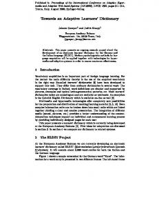
In our earlier work, high-order linear phase FIR filters were used. These provided high speech quality, but with a total filtering delay approaching 10 ms. For some applications, such as wireless communications, this delay is excessive. Therefore, we have designed a low-delay IIR filterbank using 12th-order Butterworth lowpass and highpass filters. As can be seen from the lowpass filter magnitude response shown in Figure 2, these filters have good stopband attenuation with reasonably sharp transition bands. Other IIR filter designs, such as elliptical or Chebyshev, provide sharper transitions, but have poles that are very close to the unit circle. The milder poles of the Butterworth design provide a smooth phase response in the passband, as shown by the group delay plot in Figure 3. This figure also shows that the group delay in the passband region is approximately 4 samples at the 16 kHz sampling rate, so that total delay through the filterbank is about 0.5 ms. An additional benefit of these weaker poles is that implementation in fixed-point arithmetic is straightforward.
Fig. 2. Log magnitude spectrum in dB for Butterworth lowpass filter.
25
20
Group Delay in Samples
3.1. Low-delay Filterbank
15
10
5
3.2. High-Band Quality Improvements In the baseline embedded wideband coder, the highband excitation signal is generated by sample-by-sample multiplication of a random noise source by the envelope of the 3-4 kHz region of the baseband decoder output. This method produces high-quality output for clean input speech signals. However, for lower bit rates in the presence of acoustic background noise, the lowband coder does not always code the 3-4 kHz band accurately. As a result,
0
0
500
1000
1500
2000
2500
3000
3500
4000
Frequency in Hz
Fig. 3. Group delay in samples (at 16 kHz) for Butterworth lowpass filter.
���%� ��� !%��� ���� ����%�
���%� � �0��1���� �� ���� � �
��� !"��
� . ���%� � � ������� � ���� �
#� ����#�
� � � ��� �%� ���
#� � � �� ���� ��� �/�����
� � ! � #�
� �-� � ! �� �
�� �"� ��� � ��! ����������� � �
α
#���� ������� ,� ��� �
����� ��2������ ����� � 3
�%� ���/ ���� � � ��� !"��
� !
Fig. 4. Block diagram of the highband decoder.
the output time-domain signal in this band shows more rapid time variation than the input. This, in turn, causes the high-band signal to have rapid amplitude variations, which are perceived as busy high-frequency noise upon listening. Our solution for this problem is to smooth the modulating signal at the decoder, as shown in Figure 4. This creates a more slowly varying envelope signal in the presence of background noise, and reduces the annoying “busy” noise. The equation for this smoothing is as follows: 465 798 :NMO@B4H8 :