we face in this paper, is to effectively support the designer in performing design activities on such hierarchical multi-view design descriptions. In the next section ...
An Enhanced Flow Model for Constraint Handling in Hierarchical Multi-View Design Environments Pieter van der Wolf, Olav ten Bosch and Alfred van der Hoeven Delft University of Technology Department of Electrical Engineering / DIMES Mekelweg 4, 2628 CD Delft, The Netherlands Abstract In this paper we present an enhanced design flow model that increases the capabilities of a CAD framework to support design activities on hierarchical multi-view design descriptions. This flow model offers new constructs for the configuration of complex design constraints in terms of conditions on the hierarchical multi-view structure of a design. The design flow management system enforces these constraints and uses them to inform the designer more effectively about the validity of verification results and the executability of tools. This helps to make the design process less error prone and to improve productivity. Our solution is original in that we introduce the notions of design hierarchy and equivalence in a design flow model. We thereby bridge a gap between the areas of data management and design flow management. Strong points of our solution are its simplicity and the seamless integration with existing flow management concepts.
1. Introduction CAD frameworks play an important role in building as well as in operating integrated design environments. They must help designers to keep track of the state of design and to select the most appropriate design activity that is to be performed next. The design descriptions stored in a CAD framework database can be complex hierarchical multi-view structures. Design activities may be performed at different levels in the design hierarchy and at different levels of abstraction. These design activities yield a potentially large number of interrelated partial design descriptions, each having their own status. This makes it hard for the designer to keep track of the overall state of design and plan his design activities. The problem we face in this paper, is to effectively support the designer in performing design activities on such hierarchical multi-view design descriptions. In the next section we quickly review the state of the art in CAD frameworks, to assess how far frameworks got in their evolution from design databases to design assistants. In section 3 we define in more detail the problem
������������������ This research was supported in part by the commission of the EU under ESPRIT contract 7364 (JESSI-Common-Frame). Permission to copy without fee all or part of this material is granted, provided that the copies are not made or distributed for direct commercial advantage, the ACM copyright notice and the title of the publication and its date appear, and notice is given that copying is by permission of the Association for Computing Machinery. To copy otherwise, or to republish, requires a fee and/or specific permission.
that we address and present requirements. Before taking off, we summarize our starting points in section 4. Section 5 is the key section of this paper, in which we present an enhanced flow model that allows complex constraints to be configured conveniently and permits the state of design to be represented effectively to the designer. In section 6 we present an example to illustrate the capabilities of the enhanced flow model. The implementation in the Nelsis CAD Framework is discussed in section 7. Section 8 presents our conclusions.
2. State of the Art In the early eighties, the first role allotted to CAD frameworks was that of common data repository, or design database. Subsequently, more functions were added to support the management of design descriptions, for example, to support versioning, multiple representations, etc. CAD frameworks started to fulfil a second role, that of design data manager. A design data management system maintains information about the structure and status of the design to provide management support and enforce constraints on the design process. Browse facilities were introduced to visually present this information to the designer. The third major role allotted to CAD frameworks is that of design process manager. With the increasing number of tools in today’s CAD systems, there is a growing need to support the designer in correctly executing these tools to perform his design tasks. The terms design methodology management and design flow management are both used to denote framework services that help the designer to correctly perform design activities according to a pre-defined design procedure. For example, such services may inform the designer for a particular piece of design about which tools have been run, which can be run, and which can not be run. An excellent overview of the state of the art in the area of design flow/methodology management is presented by Kleinfeldt et.al. in [1]. Typically, a design flow management system permits a design flow to be pre-defined, or configured. A design flow is the definition of a design procedure in terms of design activities which may be performed by tools, and dependencies between design activities. See, for example,
1994 ACM 0-89791-690-5/94/0011/0500 $3.50
[2, 3] and [4]. A design flow is defined in terms of the constructs provided by a design flow model. For example, several systems employ a design flow model based on a variant of the data flow paradigm [2, 4]. Several researchers [5, 6] claim that systems which require a design flow to be pre-defined are not suited to design styles that require a lot of freedom. We do not agree with this view. We take the approach that a design flow management system must allow the required degree of freedom to be configured in the appropriate design flow. Upon actual use of the design flow management system by the designer, that is, when tools are actually run to operate on design data, the system must keep track of the state of design. For this purpose the CAD framework must administer information about relevant events that affect the state of design. As shown in [2, 3] and [7], flow-based browse facilities can represent the state of design and the design history to the designer. Such facilities present the configured flow and allow this flow to be ‘colored’ with identifications of design descriptions. This may inform the designer about the derivation history of a design description or show in which design activity it may be involved next.
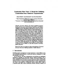
3. Problem Definition and Requirements 3.1 Global problem definition From the overview above we conclude that CAD frameworks have come a long way to assist the designer in performing the design process. However, today’s systems are still limited in their capabilities to inform the designer about the state of design for complex hierarchical multiview design descriptions. Such design descriptions are composed of large numbers of interrelated partial design descriptions, typically called design objects by the framework community. Examples of relationships between design objects are hierarchical relationships, which relate design objects upon hierarchical composition, and equivalence relationships, which relate design objects that are known to be different representations of the same design. Figure 1 presents the hierarchical multi-view structure of an example design. It shows a hierarchical layout design description with equivalent extracted circuit design objects and derived DRC-results.
DRC_RESULT
LAYOUT
=
DESIGN OBJECT
=
HIERARCHICAL RELATIONSHIP
=
EQUIVALENCE RELATIONSHIP
CIRCUIT
Figure 1. The hierarchical multi-view structure of an example design.
A major problem for a designer operating on such potentially complex design structures is to keep track of the
state of the design and to decide which design activity to perform next on which part of the design. In particular when teams of designers are operating concurrently on different parts of the design, while propagating their changes now and then, it gets hard to keep an overview of the verification status of the design and to identify parts that need to be reworked. This significantly hampers the productivity of designers and makes the design process more error prone. In this paper we study how the capabilities of CAD frameworks can be enhanced to better inform the designer about the state of design for complex hierarchical multi-view design descriptions. We want the framework to effectively support the designer in performing his design activities on such design descriptions. Consider, for example, a designer working with his fellow designers on a complex hierarchical chip layout. People working on different parts are running DRCs, netlist extractions and simulations to verify their parts, and perform updates as flaws are detected. For the designer doing the top level assembly it must now, for example, be easy to conclude that his DRC results and simulation results have been invalidated due to modification of a lower level component. The system must be able to tell him which component was modified and what its status is. Further, the system must help him to pick the best design activity to perform next and help avoid useless tool runs. For example, the system may promote DRC checks on component layouts before the activation of a routing package that assembles a compound layout from these component layouts.
3.2 Initial investigation The problem defined above touches both the areas of design data management and design flow management. Data management is concerned with the administration of the hierarchical and equivalence relationships and their consistency when changes occur. Design flow management is concerned with the execution of design activities in the right order and the presentation of the design status to the designer. Existing design flow management systems have only limited knowledge of the hierarchical multi-view structure of design descriptions. In particular the hierarchical composition of design descriptions is ignored by these systems. Their flow models do not include the notion of hierarchy (i.e. design hierarchy1). However, the above example shows that the state of a design description may depend in a complex way on the states of multiple individual design objects and the relationships that may exist between these design objects. The executability of tools and the validity of verification results for a design description may be subject to complex conditions on its hierarchical multi-view structure. This
������������������ 1. Flow models can be hierarchical in the sense that they allow design flows to be defined hierarchically. However, this is another issue for which the term hierarchy happens to be used as well.
reasoning suggests that we must somehow establish a closer link between the areas of design data management and design flow management. Our goal is to provide a framework service that is able to clearly represent the state of design to the designer, taking into account the intricate relationships among design objects, and allows complex constraints for the execution of design tools to be configured and enforced. Such a service must have at its disposal all the necessary information about the design data and the design history. This information is typically termed meta data by the framework community [8]. Modern CAD frameworks maintain meta data administrations as they track design activities. Such a meta data administration contains the domain-neutral knowledge of the CAD framework about the state of design in terms of: � the design objects and their relationships, and � the operations performed on the design objects. In this paper we focus on the exploitation of the information already present in such a meta data administration to the advantage of the designer. Publications focusing on design tracking for the administration of meta data are [5, 9, 10]. We assume that a facility for maintenance of the consistency of the administered information is already in place. Hence, all meta data in the administration is valid. For example, when a low level component in a hierarchical design is modified, the consistency mechanism invalidates the equivalence relationships for which validity can no longer be guaranteed. This may include a traversal upward in the design hierarchy to perform the invalidation. We will not discuss strategies for change propagation and consistency maintenance in this paper.
3.3 Requirements We define the following requirements for our new framework service: � The executability of tools and the validity of verification results may be subject to complex conditions on the state of design objects and the relationships among design objects. We must allow these conditions to be configured as constraints on the design process. � As the designer performs his design activities, the framework must guarantee that the configured constraints are obeyed. � The representation of the state of design to the designer must show whether or not the configured constraints are satisfied. It must be easy for him to learn which data is valid, what the history of this data is, which tools can be executed, etc. � It must be user friendly. The new service must be easy to use by both the configurator and the designer. Constraint configuration must be simple. It must be easy for the designer to understand why constraints are satisfied or violated. For this purpose the system must offer an explanation facility.
�
It must be efficient. The new service should not introduce unacceptable performance degradations. In the next section we present our starting points before presenting our solution to the defined problem in section 5.
4. Starting Points 4.1 Meta data management Our first starting point is that the hierarchical multi-view web is administered in the meta data as design objects and their hierarchical and equivalence relationships. In the Nelsis CAD Framework, meta data is organized according to a semantic data schema [11], which represents the object types known to the framework [8]. A simplified version of this data schema is shown in figure 2. HierarchyRel
VersionDerivRel
P
C
O
D
EquivalenceRel
O
D
DesignObject
Name
Vstatus
Transaction
ViewType
EqClass
Designer
Figure 2. Backbone of the Nelsis data schema. Boxes represent object types and lines connecting boxes represent attribute relationships. The central object type is DesignObject. It has the attributes Name, VersionStatus, ViewType and Designer. Via the types HierarchyRel, VersionDerivRel and EquivalenceRel, hierarchical relationships, version derivation relationships and equivalence relationships between design objects are administered. A hierarchical relationship represents the instantiation of a child design object in a parent design object. A version derivation relationship administers that a derived design object is a new version of an original design object. An equivalence relationship relates a derived design object to an original design object in a way specified by the equivalence class. The type Transaction is used to administer the operations performed on a design object.
4.2 Design flow basics Our second starting point is a flow model for the specification of tools and their interdependencies in a design flow. The Nelsis CAD Framework uses a design flow model as described in [4, 10]. Central in this model is the notion of activity. An activity is a design function of a tool. A tool may perform any of its activities any number of times during a single tool run. Because of the ability to describe the design process at the level of activities rather than at the level of tool runs, we say that the design flow model supports fine-grained design flow management. An activity has input and output ports, which describe its data access and production. The type
of an input port determines whether the data access via that port is required or optional. The viewtype of a port specifies which type of design objects can be accessed or produced via that port. Ports can be connected by channels to describe allowed data transfer. A channel connects a number of output ports (producer ports) to a number of input ports (consumer ports). Design flows can be described hierarchically using flow graphs. A flow graph is either an activity or consists of several other flow graphs, in which case it is a compound flow graph. Constructs like and’s, or’s and loops can be expressed by combining channels and ports. Figure 3 shows a design flow with flow graphs (rectangles), ports (small squares) and channels (arrows). A
C
E
B
D
F
Figure 3. An example design flow. Flow graph C needs data produced by flow graph A or B and flow graph E needs data from flow graph C and D. Flow graph B may consume data produced by itself. When an activity accesses or produces a design object via a port, this is administered by a transaction in the meta data. Each design object is created via one particular output port of one particular activity in the design flow, which is called the production port of that design object. An activity is allowed to access a design object only if it contains an input port which is connected by a channel to the production port of that design object. An activity is allowed to produce a design object only if it has an output port of the proper view type. An activity is executable with respect to a set of design objects if for all its required input ports there is a design object that the activity may access. An activity has completed successfully if it has produced a design object for all its output ports. In the user interface, the state of (part of) the design is represented by a colored flow [7]. A colored flow consists of the configured design flow, with a number of related design objects assigned to it. Design objects are related if they have been involved in the same run of an activity. A design object assigned to the design flow colors the production port of the design object, the input ports that have a channel connected to the production port, and the channel parts in between. The executability and successful completion of a flow graph is indicated by a color. DO2 DO1 A
C
B
D
E
F DO3
Figure 4. Colored flow with 3 design objects assigned.
Figure 4 shows a colored flow with design objects DO1, DO2 and DO3. Dashed flow graphs are executable and thick flow graphs have been completed. The flow coloring paradigm inherently offers powerful capabilities to visualize the intricate relationships among tools and data.
5. Enhancing the flow model The design flow model presented above permits definition of constraints on the design process that originate from the data or time dependencies between activities. Such design constraints are specified as conditions on the executability or completion of an activity based on the state of the design objects on its input and output ports. Input ports restrict the access of design objects to those of the right view type for which there exists a channel from the production port to the input port of the activity. Output ports specify which data an activity must produce in order to complete. See, for example, figure 5 which shows the activity definition for a simulator with two input ports, one for the circuit and one for the stimuli, and one output port for the simulation result. The circuit must have been produced by the circuit extractor. port1: layout
Extractor
port2: circuit
port1: circuit port2:
Simulator
port3: sim-result
stimuli
Figure 5. Activity definitions of an extractor and a simulator in a design flow.
A limitation of this design flow model is that we cannot express conditions on the state of (related) design objects for which no accesses are performed. For instance, we can not express that a layout to circuit extractor may only be executed on layouts for which all subcomponents have been DRC-ed. We want to be able to handle design constraints that take the hierarchical multi-view web of design objects into account. We introduce the notion of complex constraint. Definition 5.1: A complex constraint specifies a condition on the executability or the completion of an activity based on the relationships and the states of design objects in the hierarchical multi-view web of design objects. We investigate whether the inherent constraint definition capabilities of the basic flow model can be enhanced for expressing complex constraints in design flows. A condition on the executability or completion of an activity may relate to design objects that are not involved in a run of this activity. In order to specify such a condition, we need a way to refer to these design objects. Because we already have flow constructs to specify conditions on design objects that are involved in the activity run, it is a logical step to use the same sort of construct for design objects that are not involved in a run of this activity. We introduce a special type of port which acts as a placeholder for design objects that have to satisfy a
certain condition, even though they are not accessed or produced. We call such a port a condition port. Condition ports can be connected to channels to specify production constraints in the same way as non-condition ports. In addition to the specification of constraints on design objects by means of ports and channels, we need a construct to refer to relationships between design objects. For this, we introduce a new flow construct, the object relationship constraint (ORC). An ORC relates two ports of an activity and is used for two purposes: 1. to demand the existence of a relationship of a particular type between the design objects on the ports. 2. to specify a relationship via which a set of design objects can be found for which additional constraints must hold. An ORC has a number of attributes which define its detailed properties, like the type of relationship it refers to and the type of constraint. An ORC may refer to a hierarchical relationship (hierarchy ORC) or to an equivalence relationship of a certain equivalence class (equivalence ORC). Since hierarchical and equivalence relationships can be traversed in two directions, an ORC is a directed relationship. A hierarchy ORC demands the design objects on its ports to have a hierarchical relationship. We distinguish between recursive hierarchy ORCs, for which the design hierarchy must be traversed recursively, and non-recursive hierarchy ORCs, for which just one level must be traversed. An additional ORC attribute quantifies the set of design objects that have to satisfy the constraint. We allow three quantifiers to be assigned to ORCs: (for all), — — (none exists). Figure 6.a —� (at least one exists) and shows an activity which descends the design hierarchy of its input design object recursively. ORCs are drawn as dashed edges. Since both ports are connected to the same channel, both the parent design object and the component design objects have the same production requirements. We have the following categories of equivalence ORCs: � check equivalence ORC: An ORC of this type specifies that the activity is executable only if the equivalence of the specified equivalence class exists between the design objects on the ports of the ORC. Since an equivalence can only relate existing design objects, this type of ORC can be defined for input ports only. We allow four quantifiers to be assigned to check equivalence ORCs: (for all), — — (none exists) and O —� (at least one exists), (optional). Figure 6.b shows an activity with a check equivalence ORC. � produce equivalence ORC: An ORC of this type specifies that the activity has been completed successfully only if an equivalence relationship of the specified equivalence class has been produced between the design objects on the ports of the ORC. Figure 6.c shows an activity with a produce equivalence ORC from an input port to an output port.
�
auto equivalence ORC: An ORC of this type specifies that the activity has been completed successfully only if an equivalence relationship of the specified equivalence class exists. If the tool does not produce the equivalence, it is created automatically by the design flow management system. Figure 6.d shows an activity with an auto equivalence ORC.
rec-hier
check-equiv
a.
b.
produce-equiv
auto-equiv
c.
d.
Figure 6. The use of different types of ORCs in activity definitions.
In figure 7 we present two examples of the use of condition ports and ORCs. In figure 7.a we see an activity C which can be executed on a design object only if there exists another design object which is equivalent with the input design object via some equivalence class and which is produced by activity B and for which holds that all its children have been produced by activity B too. Condition ports are drawn as small circles. Figure 7.b shows an activity which may only execute on root design objects (the non-recursive hierarchy ORC demands that there does not exist a parent design object for the input design object).
A
check-equiv hier rec_hier C
B
a.
b.
Figure 7. The use of condition ports and ORCs. With the addition of ORCs and condition ports to the basic design flow model, we have created a flexible way of expressing complex constraints. A number of useful ORC types have been defined. With only two new flow constructs we have given the flow configurator a powerful method to enhance the configured design flow with design constraints that closely reflect the specific needs and possibilities of his design environment. This enables the design flow management system to present the state of design to the designer in a more effective way, including the adherence of the design to the configured application specific design constraints.
6. An Example Design Flow
6.2 The simulator
In this section we describe the design flow configuration for an example design environment and illustrate how the new framework service supports the designer in performing design activities. The design flow is depicted in figure 8.
Figure 10 shows the activity definition for the expensive simulator. This tool may only be executed on circuit design objects that have been derived from DRC-ed layout design objects. The circuit design object and stimuli design object are accessed via ports 3 and 5, respectively. Port 4 and ORC A indicate that the simulator traverses the circuit hierarchy recursively. ORC B and condition port 2 specify that there must exist a layout object that was used to extract the circuit object at port 3. ORC C and condition port 1 specify that this layout design object must have been DRC-ed before the simulator may be started. Port 1 has been connected to the output port of the design rule checker (see figure 8) to indicate that design objects at port 1 must have been produced by that particular design rule checker. The activity completes when the simulation result has been related to both the circuit object and the stimuli object via equivalence relationships, as specified by ORC D and ORC E. The simulation run is invalidated if one of these equivalences is invalidated.
design rule checker
expensive simulator
layout editor
extractor
results viewer simulator
stimuli editor
Figure 8. Designer’s view of a design flow for an example design environment.
The example design environment contains tools for layout design and verification. Layout design descriptions can be DRC-ed and circuit design descriptions can be extracted from them. The simulators depicted in figure 8 need two design objects, one circuit design object created by the extractor activity and one stimuli design object created by the stimuli editor activity. The stimuli object contains the simulation control statements and the simulation input data. The expensive simulator is a cpu and memory intensive tool which may only be executed on a circuit design object if the layout design object from which it was extracted has been verified by the design rule checker. We describe how the extractor and the expensive simulator have been configured using the new constructs.
6.1 The extractor
port 2: layout
port 3: circuit
port 4: circuit
port 5: stimuli
ORC C: check-equiv
ORC B: check-equiv ORC D: auto-equiv ORC A: rec-hier port 6: sim-result
ORC E: auto-equiv
Figure 10. Configurator’s view on the activity of the
The extractor tool is a single level hierarchical extractor. Its activity definition is displayed in figure 9. When invoked, the extractor derives an equivalent circuit for the layout design object at port 1. The extractor may only be invoked if the conditions as specified by input ports 1, 2 and 3 and ORCs A and B are satisfied. ORC A and port 2 specify that the children of the design object at port 1 are accessed as well. Via ORC B and input port 3, it is mandated that for each child design object there must be an equivalent circuit design object. In designer’s terms, this means that the children of the layout design object at port 1 must have been extracted previously. During extraction a circuit design object is created at port 4, and an equivalence between the design objects at port 1 and port 4 is inserted, as specified by ORC C. port 1: layout
port 1: drc-result
ORC C: auto-equiv ORC A: hier
port 2: layout
port 4: circuit ORC B: check-equiv
port 3: circuit
Figure 9. Configurator’s view on the activity of the hierarchical layout-to-circuit extraction tool.
’expensive simulator’.
6.3 The design flow in motion For the example design environment, we demonstrate how the designer is assisted in making the right tool choices. Figures 12-15 represent the state of design as shown to the designer by the flow-based browser. The representations of the activity states used in these figures are displayed in figure 11. disabled
executable
completed
Figure 11. Representations of the activity states. In figure 12, a designer has created a hierarchical layout design object A composed of design objects B-F. When he wants to perform a layout-to-circuit extraction, to be able to perform a simulation next, he notices that the extractor activity remains disabled. When he prompts the browser for the reason why, the explanation facility informs him that there are no equivalent circuit design objects for one or more of the children of layout design object A. After having extracted circuit design objects for these children, the browser updates the flow coloring and allows him to extract an equivalent circuit design object for design object A.
A B D
design rule checker
C E
F
layout editor
design rule checker
expensive
expensive
simulator
simulator extractor
extractor
layout editor
results viewer
results viewer simulator
simulator stimuli editor
stimuli editor
Figure 15. Colored design flow for design object A after
Figure 12. Designer’s view of the design flow after creation of a hierarchical layout design object.
In order to simulate his extracted circuit design object, the designer needs to create a stimuli design object with the stimuli editor. The new state of his design is displayed in figure 13. design rule checker
expensive simulator
layout editor
extractor
results viewer simulator
stimuli editor
Figure 13. Colored design flow after layout-to-circuit extraction of the hierarchical layout design object A and stimuli editing.
The simulator activity is enabled for execution, whereas the expensive simulator activity is not. When he asks the browser, the explanation facility informs him that the layout design object from which he extracted the circuit to be simulated has not been DRC-ed yet. After having remedied this omission he can simulate his design and view the result. The resulting state of design is shown in figure 14. design rule checker
modifying layout design object D.
When the designer asks how the extractor may be enabled for object A, he will be directed to object D which needs to be extracted first.
7. Implementation We have implemented the new flow constructs in the Nelsis CAD Framework. We refer to [10] for a description of the architecture of this CAD framework, and its design flow management system in particular. Nelsis has a common meta data database for data management information, design flow definition, and design flow run-time information, structured according to a single data schema. This data schema evolves as new services are added to the framework. Our new flow constructs require a small extension of the data schema, in order to permit the ORCs and condition ports to be configured. Figure 16 shows parts of the new data schema. Lines connecting corners of boxes indicate specialization. We have introduced a new object type ORC. An ORC relates a Source port to a Destination port. An ORC can be an equivalence ORC (object type EqOrc), in which case it also has an equivalence class (object type EqClass). The PortType attribute is used to distinguish condition ports. Data Management Part
expensive
EqOrc
Flow Configuration Part
simulator
Orc
EquivalenceRel layout editor
extractor
results viewer
O
S
D
simulator
D
EqClass
OrcType
stimuli editor
Figure 14. Colored design flow after simulation of the
DesignObject
Port
extracted, hierarchical circuit design object.
Now suppose that the designer does not approve of his simulation result and decides to modify layout design object D. Upon this modification the consistency mechanism invalidates the equivalence relationships between design object A and its DRC result and between design object A and its derived circuit. Note that we do not distinguish between static version binding and dynamic version binding. Upon static binding the invalidation of the equivalence may be implicit, since a new version of A gets created upon inclusion of a new version of D. Due to the (implicit or explicit) invalidations, the flow browser does not display the derived design objects. The extractor activity and the expensive simulator activity are disabled. Figure 15 displays the resulting design state.
PortType
ViewType
FlowGraph
Figure 16. Part of the new data schema for meta data management, including the object type ORC.
The design flow management system of Nelsis has been implemented as a kernel service and a flow-based user interface [10]. The kernel service keeps track of all relevant events that affect the state of design and maintains the meta data administration. It responds to requests from clients, which may be tools as well as the flow-based user interface, and notifies them when changes occur. From the tool requests it learns which activities are performed and which design objects and relationships are
accessed by these activities. The framework kernel has been enhanced with a constraint checking facility, which permits a constraint to be checked for a set of design objects. Upon access to a design object via a port, the flow management kernel has the corresponding constraint checked. Upon activity completion it checks whether for all produce equivalence ORCs an equivalence has been produced and inserts the missing equivalences for the auto equivalence ORCs. The flow-based user interface employs the principle of flow coloring, as explained in [7]. The flow coloring algorithm has been extended to produce colorings that conform to the configured constraints. When it gets notified of the invalidation of an equivalence, it has the constraints that refer to the corresponding equivalence class reevaluated. This may yield a new flow coloring in which activities have become disabled or verification results have become invalid. The evaluation of individual constraints is done via the new facility. Further, the user interface is extended with an explanation facility which allows the end-user to ask why a constraint is not satisfied. Internally this causes the user interface to re-issue the constraint evaluation and display the textual response. For example, failure of a constraint defined by a hierarchy ORC and a check equivalence ORC may produce the response: "Component D of layout A has no equivalent circuit design object". As described in [7], the flow-based user interface has been integrated with other browsers such as a hierarchy browser and a version browser.
8. Conclusion We have introduced a small number of simple constructs as extensions to a basic design flow model. These additional constructs enhance the capabilities of a design flow management system to support the designer in performing design activities on hierarchical multi-view design descriptions. The graphical user interface exploits the constraints to inform the designer more effectively about the state of design when he is executing the configured design process. This includes an explanation facility that can tell why a tool is not yet executable or why a verification result is no longer valid. Key to our solution is that we establish a closer link between design flow management and design data management. Van den Hamer and Treffers have claimed that the topics of design data management and design process management are very closely interrelated, and that a single set of concepts must handle both areas in a consistent way [2]. We share this view and believe that the simplicity of our solution is largely due to the recognition of the ‘interrelatedness’ of both topics. One may wonder why we didn’t resort to an extension language facility for the expression of complex design constraints. A language based approach could provide us with the rich set of constructs offered by general purpose programming languages. Potentially, this would make the facility for constraint definition more expressive.
However, we felt that this advantage was outbalanced by the advantages of our approach. Our solution is very simple. It yields a small number of simple constructs that perfectly fit in our approach to design flow management. The system configurator does not have to (learn and) use a language. Constraint configuration is done via some extra commands in our graphical design flow editor. The constraints directly relate to known flow constructs. The simplicity helps to keep the explanation facility simple and effective. A language based approach can make the failure of a constraint hard to explain to the designer (in his terminology). Finally we think that the simplicity of our concept contributes to an efficient implementation. Another observation is that tools may become simpler as the generic mechanisms of CAD frameworks become more powerful. In our case, if the framework guarantees that complex tool-specific constraints are adhered to, then the tools themselves would not have to check these constraints. Tool builders could then focus on the algorithmic kernel of their tool, and have the boundary conditions for its operation configured in the framework.
References 1. 2. 3. 4.
5.
6. 7.
8.
9.
10.
11.
S. Kleinfeldt, M. Guiney, J. Miller, and M. Barnes, ‘‘Design Methodology Management’’, Proceedings of the IEEE 82(2) pp. 231-250 (Feb 1994). P. van den Hamer and M.A. Treffers, ‘‘A Data Flow Based Architecture for CAD Frameworks’’, Proc. ICCAD - 90, pp. 482-485 (1990). J.B. Brockman and S.W. Director, ‘‘The Hercules CAD Task Management System’’, Proc. IEEE ICCAD - 91, pp. 254-257 (1991). K.O. ten Bosch, P. Bingley, and P. van der Wolf, ‘‘Design Flow Management in the NELSIS CAD Framework’’, Proc. 28th ACM/IEEE Design Automation Conference, pp. 711-716 (June 1991). A. Casotto, A.R. Newton, and A. Sangiovanni-Vincentelli, ‘‘Design Management based on Design Traces’’, Proc. 27th ACM/IEEE Design Automation Conference, pp. 136-141 (1990). M. Rumsey and C. Farquhar, ‘‘Unifying Tool, Data and Process Flow Management’’, Proc. EURO-DAC 92, pp. 500-505 (Sept 1992). K.O. ten Bosch, P. van der Wolf, and P. Bingley, ‘‘A Flow-Based User Interface for Efficient Execution of the Design Cycle’’, Proc. IEEE/ACM International Conference on CAD - 93, pp. 356-363 (Nov 1993). P. van der Wolf, G.W. Sloof, P. Bingley, and P. Dewilde, ‘‘Meta Data Management in the NELSIS CAD Framework’’, Proc. 27th ACM/IEEE Design Automation Conference, pp. 142-145 (June 1990). V. Vasudevan, Y. Mathys, and J. Tolar, ‘‘Damocles: An Observer-Based Approach to Design Tracking’’, Proc. IEEE/ACM International Conference on CAD - 92, pp. 546-551 (Nov 1992). P. Bingley, K.O. ten Bosch, and P. van der Wolf, ‘‘Incorporating Design Flow Management in a Framework Based CAD System’’, Proc. IEEE/ACM International Conference on CAD - 92, pp. 538-545 (Nov 1992). J.H. ter Bekke, Semantic Data Modeling, Prentice Hall, Englewood Cliffs, N.J. (1992). ISBN 0-13-806050-9.