In order to develop new automation and control systems as well as to train grid operators on new functions of the Smart. Grid appropriate methods and tools are ...
An Environment for the Coordinated Simulation of Power Grids together with Automation Systems Filip Andr´en, Matthias Stifter, Thomas Strasser Energy Department – AIT Austrian Institute of Technology Vienna, Austria {filip.andren, matthias.stifter, thomas.strasser}@ait.ac.at
Abstract—Today an increasing complexity can be observed due to the ongoing technical developments in the power and energy domain. More and more components of the electric power system, especially in the distribution grid, are equipped with digital communication interfaces and intelligent controllers. This allows a better and more comprehensive management and diagnostic of the whole electric energy system as it was the case before. This means that the future distribution system becomes a Smart Grid. In order to develop new automation and control systems as well as to train grid operators on new functions of the Smart Grid appropriate methods and tools are necessary. The goal of this paper is to introduce and describe a simulation/emulation environment which covers the physics as well as control of power systems, including supervisory tasks and communication issues. A selected example of the proposed coordinated simulation is provided and discussed. Index Terms—Power system analysis computing, power systems control, power system management, power systems simulation, voltage control, SCADA systems, Smart Grids.
I. I NTRODUCTION The future electric energy system has to deal with an increasing integration of Renewable Energy Resources (RES) in order to reduce the global greenhouse gases, especially the CO2 emissions [1]. As a result, especially the current energy production (i.e., bulk generation) is changing from a centralized to a distributed system. This change has a big influence also on transmission and distribution grids; a high degree on automation and distributed control is usually necessary in order to cope with the ever changing complexity of such Smart Grids [2]. From a technical point of view the integration and active networking of existing and new components as well as the corresponding automation and control concepts are necessary in order to manage the upcoming high complexity of the future power grids [3]. This can only be reached if innovative methods from the Information and Communication Technology (ICT) domain are taken into account. Therefore, a focus on the further research, development and education addressing the needs of the future Smart Grid is essential. This means, that topics related to the electrical power system, control and ICT have to be addressed in a holistic manner [4]–[6]. With the realization of such cyber-physical power system also appropriate testing and validation approaches are of high importance. In this context the validation of system behavior as well as corresponding devices and components (e.g., in-
verter systems, battery charging devices, current limiters, and controllers) are very important. Moreover, their integration become an essential part of the Smart Grid planning and development and has to be done before the deployment of the system in the power grid is accomplished. [7] The main aim of this paper is to address both topics; the electrical power system as well as the ICT/automation part and to introduce a corresponding simulation/emulation environment for Smart Grid research, development, validation and training. Because a comprehensive emulation of both worlds (power and ICT systems) in one multi-domain simulator is hardly achievable, a coordinated simulation of the power grid together with automation systems is suggested and introduced. The proposed co-simulation approach is characterized by using a power system modeling and simulation environment where detailed component models are simulated in a dedicated tool. Automation and control algorithms are emulated in a control systems tool and the supervisory tasks and system operation are carried out in a connected Supervisory Control and Data Acquisition System (SCADA). The rest of the paper is organized as follows: A brief description of the related work and state-of-the-art regarding simulation of power and energy systems is given in Section II. Section III provides an overview of the proposed co-simulation concept whereas in Section IV the used modeling and simulation environment covering the physical system and ICT-related topics is described. A simple simulation example which is used for education and training purposes is introduced in Section V. This example serves also for the validation and proof-ofconcept of the proposed co-simulation approach. Finally, the summary and the conclusions are provided in Section VI. II. R ELATED W ORK The importance of simulation methods for the development of Smart Grid systems and applications has already been stated as a very important topic by Podmore and Robinson [8]. The existing approaches and tools for power systems and device simulation can be divided into offline steady state, offline transient and real-time simulation. Offline steady state simulation comprises power flow, optimal power flow, reliability computations etc. whereas offline transient simulation comprises time domain simulation with no real-time constraint. In addition, real-time simulation is basically time domain simulation with the additional constraint that time available
for computation of the next state and output is limited. A very good overview of common modeling and simulation approaches in this area is provided by Milano [9]. All of this approaches have in common that they are covering mainly continuous time models [10]. On the other hand communication and control models— which are also very important for Smart Grid systems—are more related to discrete event simulation and therefore need different modeling and simulation approaches [10]. Another interesting simulation-related experiment is described by Steurer et al. [11]. The approach of applying controller-hardware-in-the-loop simulation method in power and energy systems for validating control functions is described. Simulation of physical models is realized in realtime simulators and control algorithms are executed on real controller hardware. This is of great interest for Smart Grids applications where real world tests of devices are often hardly possible during there development. It has to be noted that individual domains covered by Smart Grids—power grid, communication system, controllers—have been modeled and simulated separately in the past. New requirements in the Smart Grid context demand for the first time a simultaneous coverage of both domains in energy system simulation [10]. Summarizing, most of the above mentioned work either focus on a very detailed analysis of the power grid and its connected components (e.g., generators, loads, storages, switches, breakers) or the simulation and emulation of automation and control functions. In some work coupling of the different domain models in a co-simulation environment has already been covered with a focus either on the physical system, the communication network or the controllers. The integration of automation and supervisory tasks—which are also very important for future power systems—has not been discussed in detail so far as it is covered by this work. III. C O -S IMULATION C ONCEPT: M OTIVATION , R EQUIREMENTS AND A RCHITECTURE A. Background and Motivation The main idea of the co-simulation environment—proposed in this paper—is to provide a flexible concept for simulation and development of automation systems as well as corresponding functions (incl. SCADA, distributed control and communication aspects) for its usage in the domain of Smart Grids. This includes automation concepts and algorithms for different control levels in the electrical grid, e.g., on component level as well as on a management level. Thus the simulation environment must be flexible enough to cope with simulations of electrical energy grids combined with detailed simulations of the grid components. Moreover, educational aspects are also addressed with this simulation concept. Before the newly developed control algorithms and automation concept can be installed in the field, the grid operators have to be trained in advance on the new features and functions. Normally, an online training direct in the field is not always possible or of high risk. A
simulation/emulation environment therefore seems to be a very good alternative. Since such an emulated environment has to cover different real world use cases, the corresponding models have to be detailed enough and need to cover physical issues as well as automation and communication related topics. In principle such an environment can be realized within a multi-domain simulator or with a coupling of different, highly specialized simulation/emulation tools. Due to the fact that the ICT domain—incl. SCADA system, visualization, communication network, device controllers, etc.—has to be modeled and simulated together with power system physics, high demands are put on a multi-domain simulation tool. In the rest of this paper a co-simulation approach is used since it seems to be more suitable to address the challenging requirements for Smart Grid system design, development, implementation and validation. B. Requirements for Coordinated Simulation of Power Systems In order to realize a co-simulation environment for Smart Grid systems as motivated above, the following main requirements have to be taken into account: • Covering multiple domains: Different components of a Smart Grid system that have to be adequately modeled by the simulation environment, covering the physical system, the underlying communication network, control algorithms and automation/supervisory functions. • Scalability and extendability: The modeling and simulation framework must allow simulating problems of different sizes (from a very detailed analysis of grid parts and components up to a large distribution network with all connected components like generators, loads, etc.). • Flexible simulator coupling: Depending on the scope of the simulation different coupling methods between the four model domains (power grid, communication network, control algorithms and automation/supervisory system) must be possible. The coupling methods, besides the model granularity, have a major impact on simulation performance and result accuracy. • Integration of real components: In order to be as close as possible to the real world either detailed models of the physical as well as ICT components have to be integrated in the emulation environment. Sometimes, the implementation of detailed models is time consuming or not always possible due to high complexity. The connection of real components in a laboratory environment to the co-simulation framework has to be supported too. C. Concept and Architecture The proposed co-simulation concept is shown in Fig. 1. The concept uses a power system analysis tool for the overall simulation of electrical energy systems. For detailed analysis of the connected grid devices (if necessary) a component simulator is used which is interfaced to the grid simulator. Control components can be either low level control components for automation of the grid components or high level control components for the overall supervisory control and
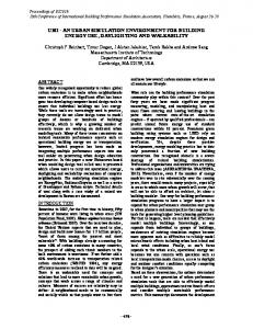
management of the power grid. Thus control components must be properly interfaced to the different simulation tools. Since control components are also dependent on information from each other, interfaces between the control components have to be provided too. In addition, also the communication network between the different ICT/automation components as well as control devices needs to be taken into account in this co-simulation environment. Especially communication related issues can have a big influence on the operation of the whole automation system. For example, data losses as well as delayed messages can influence management and control algorithms and therefore also the operation of the Smart Grid. This could lead to undesired system behavior and grid instability and needs to be properly addressed. A detailed analysis of such effects can be carried out in such a co-simulation environment. HV/MV Network
Power Grid Simulation
HV/MV Network
MV/LV Substation
Distributed Energy Resource DER (e.g. PV, wind, etc)
MV/LV Substation ~
Breaker/Switches
~
Communication Network
Stationary Loads (e.g. Buildings, etc.)
Feeder
Moveable Loads (e.g. ElectroVehicles, etc.)
local I/Os
(DER) Component Simulation
IED Central Voltage Control
local I/Os
IED Local Control
IED Local Control Communication Network
Controller Emulation
IED Local Control
Fig. 1. Overview of the coordinated simulation environment.
IV. M ODELING AND S IMULATION E NVIRONMENT This section provides an overview of the modeling approaches used for the different parts of the proposed cosimulation environment. The different tools used for the specific simulations provided by this approach are also described. Moreover, the possibilities of coupling the simulation environment together as well as the used interfaces are discussed. A. Simulation Tools and Environments The co-simulation environment for Smart Grid systems consists of the following five parts: 1) Power Grid Modeling: For the study of power systems general models are used. They are usually composed out of simplified component models, especially for investigations of operation strategies and interactions between the grid, generators, loads and storage devices. Normally, for such simulation experiments the simple power flow analysis is used. Compared
to the proposed structure of a general purpose software suite for power system analysis, as described by Milano [12], separate simulations of the grid components correspond to external power flow simulations used for analysis. For the proposed cosimulation environment the commercial power system analysis simulation suite DIgSILENT PowerFactory [13] is used. The reason for this choice is the availability of several algorithms and system models provided by this tool. Among various other functions, power flow, short circuit, harmonic and stability analysis as well as steady state simulations are possible, which are of interest for the topic discussed in this paper. 2) Detailed Modeling of Grid Components: In addition to the above described modeling approach sometimes a much more detailed view on the connected components (e.g., substation, DER devices, loads, breakers, switches, inverters) is required. Such a detailed analysis of the components is not directly covered by the DIgSILENT PowerFactory tool. Therefore, in this co-simulation environment the MATLAB/Simulink environment [14] is suggested. The main reason for using MATLAB/Simulink is the availability of various toolboxes (e.g., SimPowerSystems) with validated models of different components. Moreover, component models can be developed in this environment in a reasonable time. A further advantage of this choice is the possibility of direct coupling with DIgSILENT PowerFactory. 3) Communication System Modeling: As already mentioned before, also the underlying communication infrastructure which connects the management and automation tools with power grid components in a Smart Grid can have a big influence regarding operation [10]. For example, a time delay or a packet loss in a control loop can lead to undesired behavior. Therefore, also the analysis of the information and data exchange in a Smart Grid system is important. Similar to the physical model of the power grid, simple but also detailed models of the communication network are needed for different purposes in the proposed co-simulation environment. There are several interesting commercial (e.g., OPNET, NetSim) and open source tools (e.g., OMNeT ++, ns-3) for communication simulation available on the market. For this work, this part of the co-simulation environment have not been analyzed in detail so far. This is subject for future research. 4) Control Algorithm Modeling: The approach which is applied in this paper will focus on the control algorithm definition and implementation using the IEC 61499 reference model for distributed automation and control systems [15]. This standard is suggested as promising implementation language and candidate for control algorithms and Intelligent Electronic Devices (IED) according to IEC 61850 [16] in Smart Grid applications [17], [18]. One of the main advantages of the IEC 61499 is the fact that the developed control algorithm models are executable. This means that they can be executed in a simulation environment but also in the real hardware environment with a minimal amount of adaptation work [19]. In the proposed co-simulation environment, the IEC 61499 compliant open source framework 4DIAC is used since it provides an open and extensible control framework [20] which
is essential for research purposes. Other control approaches and tools could be used in this environment as well. 5) Supervisory System Modeling: SCADA systems for supervisory control, monitoring and diagnostics are widely used for the operation and management of power transmission (called Energy Management Systems) and distribution systems (called Distribution Management Systems). They usually interact with distributed controllers (e.g., RTUs1 , PLCs2 , IPCs3 ) on the field level via common SCADA system communication protocols (e.g., IEC 60870, IEC 61850, OPC-DA/UA, CIM, TCP/IP, UDP/IP). For research and educational purposes the open source tool ScadaBR [21] is used in the proposed cosimulation environment. The reason for this choice is similar to the control algorithm modeling one, as an open source tool provides the possibility for easier extension of features, functions and protocols compared to commercial tools. B. Simulator Couplings and Interfaces For the proposed co-simulation environment simple TCP/IP interfaces between the tools were used in a first step. The information model used is an ASN.1 code [15] which is simple to implement and it is used in the IEC 61499 standard for the data exchange over TCP/IP or UDP/IP. All of the used tools also provide this interface or provide possibilities to implement it as shown in Fig. 2.
Grid Component Simulation (e.g., Distributed Energy Resources)
Supervisory Control and Monitoring Simulation
Component Simulation
SCADA Emulation
ASN.1 over TCP/IP
Electricity Grid Simulation
Power System Analysis
ASN.1 over TCP/IP
ASN.1 over TCP/IP
Controller Emulation
(Embedded) Control System Development and Simulation
Fig. 2. Co-simulator couplings and used communication interfaces.
1) Power Flow Interface: The interaction between DIgSILENT PowerFactory and MATLAB/Simulink is based on the power flow calculation of the simulated grid in DIgSILENT PowerFactory and the component simulation in MATLAB/Simulink. DIgSILENT PowerFactory provides grid voltage and grid frequency to MATLAB/Simulink, which provides generated active and reactive power to DIgSILENT PowerFactory. It is important that these simulations are synchronized with each other, therefore a synchronization mechanism is required. The solution applied was to use DIgSILENT PowerFactory as simulation master, i.e., each simulation step in DIgSILENT PowerFactory triggers a component simulation of the same step in MATLAB/Simulink. 1 Remote
Terminal Unit Logic Controller 3 Industry PC 2 Programmable
2) Control Interface: On one hand the control interface is the interface between the control components and the power system simulations; on the other hand it is also the interface between the control components themselves. The communicated data and information consists of measurements and set points. Usually such co-simulations are performed using Hardware-in-the-Loop (HIL) simulations running in real-time [11]. Due to the physical decoupling between the power and control systems, and the use of real-time simulations, there is no need for an additional synchronization mechanism of the control interface. In addition a communication interface between the device level control, which is modeled in the IEC 61499 4DIAC environment and the SCADA system level (i.e., ScadaBR) is necessary. In a first step the same mechanism (i.e., ASN.1 over TCP/IP) as for the grid and component simulator coupling was applied. In the future a more sophisticated modeling and simulation approach is planned, taking also the communication network and corresponding SCADA system protocols (e.g., IEC 60870, IEC 61850) into account. V. S IMULATED E XAMPLE AND R ESULTS In order to show how the proposed co-simulation environment can be used for development and validation of Smart Grid automation concepts, as well as for training and educational issues, a simple example was chosen, which will be explained below. A. Test Case Motivation and Scenario Description The goal of this simplified co-simulation example was to implement a voltage control algorithm with the 4DIAC environment and to emulate the supervisory control and the visualization with the ScadaBR tool. The idea of the simulation is to present and discuss how the co-simulation environment can be used to design automation algorithms for Smart Grids. To show this issue the following scenario is used: A power system simulation is executed using DIgSILENT PowerFactory. This is coupled with a detailed simulation of a PV system in MATLAB/Simulink and with a control algorithm emulation in 4DIAC. For the power grid model a simple low-voltage grid connected to an onload tap-changer with RES have been modeled in the DIgSILENT PowerFactory environment. The goal of the control algorithm simulated in 4DIAC is to control the tap-changer of the transformer to keep the voltage in the grid within the allowed limits. 1) Power System Model: A model of a typical rural 0.4 kV low-voltage (LV) grid was simulated using DIgSILENT PowerFactory, as seen in Fig. 3. It consists of three feeders with 13 loads representing households and 9 PV systems. The feeders are between 200 and 250 meters. Although the network model can be used for unbalanced analysis (3 phase / 4 wires) with the earthing impedance modeled in place, for this simulation it is simulated as a balanced, symmetric system. Load profiles are represented by 10 minute mean values, based on real 1 second measurement data [22].
A simulation step size, TP S , of 10 minutes was used for this experiment. Since the model uses power profiles for the loads and the generation with a sample time of 10 minutes no dynamics can be simulated and thus the relative long step size is motivated. For the co-simulation the power system model was connected with a detailed simulation of a PV system and a tap-change controller, marked green and orange in Fig. 3.
3) Central Voltage Controller: In order to keep the voltage between its allowed limits, a tap-change controller was implemented and simulated in 4DIAC. This algorithm is shown in Fig. 5. The algorithm receives the current voltage from some selected measurements in the grid together with the actual tap position of the transformer. If this voltage is higher or lower than certain specified limits, Vmax and Vmin , the algorithm increases or decreases the current tap position by one step and sends the new position to the power system simulation in DIgSILENT PowerFactory, where it is applied to the transformer tap changer model.
Fig. 5. Voltage controller implementation.
Fig. 3. Power distribution system model.
2) PV Model: A detailed PV system model was executed in MATLAB/Simulink, as seen in Fig. 4. The model consists of an inverter and a PV module, which uses a profile as input. The generation profile used for this simulation experiment has a resolution of 1 second sample time. The simulation in MATLAB/Simulink is connected with and controlled by the power system simulation in DIgSILENT PowerFactory. Because of the higher time resolution model in MATLAB/Simulink, the PV model is simulated using a smaller time step, TP V , of 1 millisecond. Thus, when the simulation is triggered by DIgSILENT PowerFactory, MATLAB/Simulink simulates 10 minutes using its own time step. DIgSILENT PowerFactory provides the PV model with the current grid voltage. This voltage is used during the 10 minutes simulation in MATLAB/Simulink. Once the detailed simulation is finished the resulting active and reactive power is returned to DIgSILENT PowerFactory, which uses these results as further inputs.
powergui
Ppv
Ppv Ppv
Ug
From Workspace
Scope1 PV Grid
Fig. 4. PV system component model.
The control algorithm is modeled and executed in the IEC 61499 environment 4DIAC. Since IEC 61499 defines an event-based control flow this has some consequences for the control model and the execution used in the co-simulation experiment. If dynamics are simulated, a timing behavior must be included in the control model since it has no own execution cycle. In case when no dynamics are simulated, no special considerations have to be made for the control model. The model is only executed once when new data are received, which is sent by DIgSILENT PowerFactory once every simulation step TP S . From the point-of-view of the power system simulation, the control algorithm is executed without any delay, however with a simulation step of 10 minutes this is a reasonable simplification. 4) SCADA System: In the ScadaBR tool a sketch of the used power distribution grid as well as a simple animation, showing the bus voltage at the transformer and at the PV system, was implemented. It is possible to switch on/off some distribution feeders. Fig. 6 shows the simplified SCADA application. B. Simulation Results The following Fig. 7 provides an overview of the simulation result of the used co-simulation example. The upper plot shows the power fed into the grid by the PV system modeled in MATLAB/Simulink, the middle plot shows the highest voltage in the grid, which was measured at the PV system (marked green in Fig. 3) and the voltage at the transformer. As it is seen in this figure, the voltage rises when the PV generation increases after 06:00. When the voltage reaches Vmax = 1.05 it causes the control algorithm to increase the tap position, which decrease the voltage. VI. S UMMARY AND C ONCLUSIONS A co-simulation environment covering electric power system and detailed component models of distributed generators together with automation and SCADA systems is introduced.
ACKNOWLEDGMENT This work is supported by the Austrian Climate and Energy Fund and by the Austrian Research Promotion Agency (FFG) under the project “DG-EV-HIL”. R EFERENCES
Fig. 6. Supervisory tasks with SCADA tool.
Power [kW]
0 −2 −4 −6
0
3
6
9
12 Time [h]
15
18
21
0
Voltage [p.u.]
1.1 V Transformer V PV
1.05 1 0.95
0
3
6
9
12 Time [h]
15
18
21
0
0
3
6
9
12 Time [h]
15
18
21
0
Tap position
1.5 1 0.5 0 −0.5
Fig. 7. Simulation results: PV power, grid voltage and tap position.
Also the communication network in a Smart Grid application is addressed by this concept. This approach is able to analyze complex behavior of future Smart Grids and provides an environment for validation of control functions. It is suitable for training and education of students and operators. A simple voltage control example covering three domains— electric power system, automation and supervisory control— has demonstrated the practical usage of the proposed approach. The future work is focused on the integration of a more detailed model of the communication network and its corresponding SCADA system protocols.
[1] IEA, “World Energy Outlook 2009,” International Energy Agency (IEA), Paris, Tech. Rep., 2009. [2] ——, “Technology Roadmap, Smart Grid,” International Energy Agency (IEA), Paris, Tech. Rep., 2011. [3] M. Liserre, T. Sauter, and J. Hung, “Future energy systems: Integrating renewable energy sources into the smart power grid through industrial electronics,” Industrial Electronics Magazine, IEEE, vol. 4, no. 1, pp. 18–37, Mar. 2010. [4] H. Farhangi, “The path of the smart grid,” Power and Energy Magazine, IEEE, vol. 8, no. 1, pp. 18–28, Jan.-Feb. 2010. [5] V. Gungor, D. Sahin, T. Kocak, S. Ergut, C. Buccella, C. Cecati, and G. Hancke, “Smart grid technologies: Communication technologies and standards,” Industrial Informatics, IEEE Transactions on, vol. 7, no. 4, pp. 529–539, Nov. 2011. [6] SMB Smart Grid Strategic Group (SG3), “IEC Smart Grid Standardization Roadmap,” International Electrotechnical Commission (IEC), Geneva, Switzerland, Tech. Rep. Ed. 1.0, 2010. [7] S. Amin, “Electricity infrastructure security: Toward reliable, resilient and secure cyber-physical power and energy systems,” in Power and Energy Society General Meeting, 2010 IEEE, Jul. 2010, pp. 1–5. [8] R. Podmore and M. Robinson, “The role of simulators for smart grid development,” Smart Grid, IEEE Transactions on, vol. 1, no. 2, pp. 205–212, Sep. 2010. [9] F. Milano, “An open source power system analysis toolbox,” Power Systems, IEEE Transactions on, vol. 20, no. 3, pp. 1199–1206, Aug. 2005. [10] H. Lin, S. Sambamoorthy, S. Shukla, J. Thorp, and L. Mili, “Power system and communication network co-simulation for smart grid applications,” in Innovative Smart Grid Technologies (ISGT), 2011 IEEE PES, Jan. 2011, pp. 1–6. [11] M. Steurer, F. Bogdan, W. Ren, M. Sloderbeck, and S. Woodruff, “Controller and power hardware-in-loop methods for accelerating renewable energy integration,” in Power Engineering Society General Meeting, 2007. IEEE, Jun. 2007, pp. 1–4. [12] F. Milano, Power System Modelling and Scripting. Springer, Jan. 2010. [13] DIgSILENT, “Combined Transient and Steady State Simulation (RMSEMS),” DIgSILENT GmbH, Tech. Rep., 2007. [14] Matlab/Simulink, “The language of technical computing,” Mathworks, Tech. Rep., Access Date: February 2013. [Online]. Available: http://www.mathworks.com [15] IEC, IEC 61499: Function blocks, International Electrotechnical Commission (IEC) Std., Rev. 2nd Edition, 2012. [16] ——, IEC 61850: Communication networks and systems for power utility automation, International Electrotechnical Commission (IEC) Std., Rev. 2nd Edition, 2010. [17] DKE, “The German Standardisation Roadmap E-Energy/Smart Grid,” German Commission for Electrical, Electronic & Information Technologies of DIN and VDE, Frankfurt, Germany, Tech. Rep., 2010. [18] G. Zhabelova and V. Vyatkin, “Multiagent smart grid automation architecture based on IEC 61850/61499 intelligent logical nodes,” Industrial Electronics, IEEE Transactions on, vol. 59, no. 5, pp. 2351–2362, May 2012. [19] T. Strasser, M. Stifter, F. Andren, D. Burnier de Castro, and W. Hribernik, “Applying open standards and open source software for smart grid applications: Simulation of distributed intelligent control of power systems,” in Power and Energy Society General Meeting, 2011 IEEE, Jul. 2011, pp. 1–8. [20] A. Zoitl, T. Strasser, and A. Valentini, “Open source initiatives as basis for the establishment of new technologies in industrial automation: 4diac a case study,” in Industrial Electronics (ISIE), 2010 IEEE International Symposium on, Jul. 2010, pp. 3817–3819. [21] ScadaBR. (Access Date: February 2013) Open-Source Data Acquisition System. [Online]. Available: www.scadabr.com.br [22] ESEA, “Adres-concept load profiles,” http://www.ea.tuwien.ac.at/ projekte/adres concept.