MATHEMATICAL COMPUTER MODELLING
PERGAMON
Mathematical
and
Computer
hlodelling
36 (2002)
461-471 www.elsevier com/locate/mcm
An Exact Approach for Batch Scheduling in Flexible Flow Lines with Limited Intermediate Buffers T. SAWIK University Department
of Mining
of Computer
Al. Mickiewicza
and Metallurgy
Integrated
30, 30-059
Manufacturing
Krakow,
Poland
[email protected]
(Received March 2002; accepted April 2002) Abstract-The paper presents a mixed integer programming approach for makespan mmimization in flexible flow lines. The line consists of several processing stages in series, separated by finite intermediate buffers, where each stage has one or more parallel identical machines. The problem objective is to determine a minimum length schedule for a mix of part types, where identical parts are scheduled consecutively. The limited intermediate buffers between the stages result in a scheduling problem with machine blocking, where a completed part may remain on a machine and block it until a downstream machine becomes available. Numerical examples modeled after real-world surface mount technology lines for printed wiring board assembly are provided and some computational results are reported to illustrate the approach. @ 2002 Elsevier Science Ltd. All rights reserved.
Keywords-Batch scheduling, Surface mount technology line.
Mixed integer programming,
Hybrid flowshop,
Limited
buffers,
NOMENCLATURE 9
batch (part type), g E G =
ma
number of parallel processors stage 2
n
total number of parts
tI,...,V) i
processing
stage, 2 E I = { 1,.
3
processor
in stage Z, J E Jz =
, m}
T,9
{I,...,m,) k
part,kEK={l,...,n}
size of batch g (number of parts of type 9)
m
processing time in stage i of part type 9
Input Parameters b,
in
IJ
number of batches (part types)
K9
subset of parts of type g
Qafg
large numbers not less than the schedule length
number of processing stages
This work has been partially supported Center (U.S.A.).
by AGH and KBN (Poland)
and by the Motorola
0895-7177/02/$ - see front matter @ 2002 Elsevier Science Ltd. All rights reserved. PII: SO895-7177(02)00176-0
Advanced
Typeset
Technology
by d,#IBX
T.
462 Decision Variables
1%~k
c max
schedule length
C,k
completion
d Iii
SAWlK
&Jk
time of part k in stage i
departure time of part k from stage 2
1, if part k is assigned to processor J E J, m stage i E I; otherwise
y.fLJ
=
0
1, if batch f precedes batch 9; otherwise yfg = 0
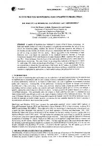
1. INTRODUCTION A flexible flow line (FFL) consists of several processing stages in series, separated by finite intermediate buffers, where each stage has one or more parallel identical machines, e.g., [l]. The line produces several different part types. Each part must be processed by at most one machine in each stage. A part which has completed processing on a machine in some stage is transferred either directly to an available machine in the next stage or to a buffer ahead of that stage. The limited intermediate buffers between the stages result in a blocking scheduling problem, e.g., (2,3], where a completed part may remain on a machine and block it until a downstream machine becomes available. This prevents another part from being processed on the blocked machine. A practical example of an FFL is an automated surface mount technology (SMT) line for printed wiring boards assembly (see [4]), which includes three different processes in the following sequence: solder printing, component placement, and solder reflow. An example of an SMT line with parallel stations is shown in Figure 1. The line consists of a board loader, a solder printer, two parallel placement machines for small components, and two additional shuttles routing the board to the next available placement machine, one placement machine for fine pitch components, and a reflow oven. The assembly process is as follows: a tote of bare (preassembly) boards is brought to the beginning of the line, and a material loader loads each board separately on the conveyor. Each board is transported by the conveyor system through each processing stage in the line and then is stored again in a tote box. The loader and the tote box are used as the input and output buffers of the line. There are external buffers in front of and behind each placement machine, except the last one. In addition, every placement machine has its own internal input and output buffers of a fixed capacity.
Figure 1. An SMT line with parallel stations.
The objective of an FFL scheduling is to determine the detailed sequencing and timing of all processing tasks for each individual part, so as to maximize the line’s productivity, which may be defined in terms of throughput or the schedule length (makespan) for a mix of part types. The problem of minimizing makespan in an FFL line is clearly NP-hard. An FFL line is a generalization of a multistage hybrid flowshop with parallel identical machines in each stage and unlimited intermediate buffers. Minimizing makespan in the hybrid flowshop is NP-hard, e.g., (51. Also, the m-machine flowshop with finite intermediate buffers is NP-hard even for m = 2 (see [6]). Furthermore, well solvable special cases such as two-machine flowshops with unlimited buffers [7] or with no buffers [8] are not directly applicable in the FFL environment.
463
An Exact Approach
In practice, to executing
scheduling of an FFL daily production
is often based on daily demands and a simple approach
plan is the use of batch scheduling, where parts of one type are
processed consecutively. finite intermediate
Since the batch sequencing problem in the two-machine flowshop with a buffer is NP-hard (see [9,10]), minimizing makespan in the batch scheduling
of a flexible flow line is NP-hard In high-volume
production,
as well. the production
plan is often split into several identical
sets of
smaller batches of parts that are scheduled repeatedly.
The smallest possible set of parts in
the same proportion as the daily part mix requirements
is called the minimal part set (MPS),
e.g., [11,12]. Research on scheduling algorithms for FFL is mostly restricted to heuristics which seek good solutions within reasonable computation times, e.g., [1,3,12,13]. This paper, however, provides the reader with an exact approach based on a mixed integer programming
formulation
FFL scheduling problem, e.g., [4,14-161. The formulation can be applied for constructing
of the optimal
batch schedules for small size batches of different part types (e.g., for MPS) and for various FFL configurations by using commercially available software for mixed integer programming. This has been illustrated in the paper with numerical examples that have been modeled after real-world SMT lines using an advanced algebraic modeling language AMPL and the CPLEX solver. The paper is organized as follows. In the next section, a mixed integer programming formulation is presented for batch scheduling in a flexible flow line with machine blocking. Numerical examples modeled after real-world SMT lines and some computational results are provided in Section 3, and conclusions are given in the last section.
2. MIXED INTEGER PROGRAM FOR BATCH SCHEDULING A FLEXIBLE FLOW LINE WITH MACHINE BLOCKING In this section,
a mixed integer programming
flexible flow line with limited intermediate
IN
model is presented for batch scheduling in a
buffers.
A unified modeling approach is adopted with the buffers viewed as machines with zero processing times. As a result, the scheduling problem with buffers can be converted into one with no buffers but with blocking, e.g., [3,15]. The blocking time of a machine with zero processing time denotes part waiting time in the buffer represented by that machine. We assume that each part must be processed in all stages, including the buffer stages. However, zero blocking time in a buffer stage indicates that the corresponding part does not need to wait in the buffer. Let us note that for each buffer stage part completion time is equal to its departure time from the previous stage since the processing time is zero. Notation used to formulate the problem is shown in the Nomenenclature,
where buffers and
machines are referred to as processors. The flexible flow line under study consists of m processing stages in series. Each stage i, m) is made up of m, 2 1 identical parallel processors. Let ._7,be the circular set (i = l,..., of indices of parallel processors in stage i. The system produces various types of parts. Let G = Cl,. , v), K = (1,. . . , n), and &, = {CfEG:f.+g_l b, + 1,. . . , CfEG:f.+g-l bf + b,} be the ordered sets of indices, respectively, of all batches of parts, all individual parts, and all parts of type g E G. (bg, n = Cg=, b,, and v denote, respectively, the number of parts of type g, the total number of parts, and the number of batches in the schedule.) All parts are scheduled in batches of parts of the same type and within the batch individual parts are processed consecutively part-by-part. No setups are required between different parts or different batches of parts. Each part must be processed without preemption on exactly one processor in each of the stages sequentially. That is, each part must be processed in Stage 1 through Stage m in that order. The order of processing the parts in every stage is identical and determined by an input sequence in which the parts enter the line, i.e., a so-called permutation flowshop is considered.
T. SAWIK
464
For every part
k, denote
time in each Stage i, and by d,k its departure
by c& its completion
time from Stage i. Let rsg 2 0 be the processing preemption
indicates
that
time in Stage i of each part
part k f KS completed
type g E G.
Processing
in ‘Stage i at time c& starts
without
its processing
in
that stage at time c,k - rZg. Part k E Kg completed in Stage i at time c& departs at time d,k 2 C& to an available processor in the next Stage i + 1. If at time c& all m,+r processors in Stage i f 1 are occupied,
then
the processor
in Stage i is blocked
by part
k until
time d,k = c,+lk_ - r,+lg
when part k E Kg starts processing on an available processor in Stage i + 1. The objective is to determine an input sequence of batches and an ~signment processors
in each stage over a scheduling
that is, to minimize
the makespan
of part k in the last stage m. The mixed integer program buffers is presented Minimize
C,,,
horizon
to complete
= max&K(Cmk),
for batch
scheduling
all the parts
where Cmk denotes
in a flexible
of parts
time,
the completion
time
fiow line with finite
in-process
below. c max,
subject to part ussign~e~~
(1)
con~tru~nts
=1;
t3
hjk JEJ, +xxt(j,J,),kfl
to
in minimum
i E
%k;
=
I,
Jo
i
E
k E K,
I,
Jz, gEG>
(2)
k E Kg : k < last (Kg),
m, > 1;
(3)
part completion construints Clk
> rig;
cak - c%-lk 2 rag;
9 E G,
k E Kg,
i E I,
gEG,
(4 kEKg:i>l;
(5)
part depu~uTe constraints
part noninte~fe~nce
c,k 2 dzlc;
i E I,
cnak = drnk;
k E K;
(6) (7)
construints cak + i E I,
Qa.fg(2 + Yfg
j c 4, %I + Qwt3
i f I, buffenng
kEK:i d,l f r,f;
f,g E G,
lEKg:f
f,gEG,
ZEKg:fl;
(10)
maximum completion time constraints
d,k f
1 hEf:h>z
cnak 2 Gmax;
k E K,
rhg < Grnax;
i E I,
g E G,
k E Kg : i < m,
(11) (12)
An Exact Approach
Cd
-
Cl1 5
c
cm, -
465
c >g bjw
b_P-lf~fv -
%i
(1- ~gj) -
jEG:j
fEG:fg
G,
gE
lEKg:rnr=l,
m,=1;
batch processing constraints Czk+m,
i E I,
g E G,
2 c,k;
i E I,
g E
G,
> d,k + rtg;
i E I,
g E
G,
>
cak+l cak+l
& + rtg;
variable elimination
< last(K,),
m, > 1,
(14)
k E Kg : k < last(K,),
ml > 1,
(15)
k E Kg : k < last(K,),
m, = 1;
(16)
constraints Yfg =
variable
k E Kg : k+m,
0;
f,gEG:.f
29;
(17)
nonnegativity and integrality constraints ctk
i
2 0;
dzk 2 0; +k
c
I,
k E K,
i E I,
k E K,
E
i E
{&I};
I,
~EJ,,
(18) (19) kEK,
(20)
f,g E G.
Yfg E (07 11;
(21)
The objective function (1) represents the schedule length to be minimized. Assignment constraint (2) ensures that in every stage each part is assigned to exactly one processor, and (3) assigns successive parts of one type alternatively to different parallel processors (next(j, Jz) is the next processor after j E J, in the circular set J, of parallel processors at Stage i). Constraint (4) ensures that each part is processed in the first stage, and (5) guarantees that it is also processed in all downstream stages. Constraint (6) indicates that each part cannot be departed from a stage until
it is completed
in this stage,
and equation
(7) ensures
that
each part
leaves the line
as soon as it is completed in the last stage. Constraints (8) and (9) are part noninterference constraints. No two parts can be performed on the same processor simultaneously. For a given sequence of parts, only one constraint of (8) and (9) is active, and only if both parts k and 1 are assigned to the same processor. Equation (10) indicates that processing of each part in every stage starts immediately after its departure from the previous stage. Constraint (11) defines the maximum completion time of all parts. Constraint (12) relates part departure times to makespan directly. Every part must be departed from a stage sufficiently early in order to have all of its remaining tasks completed within the remaining processing time. Constraint (13) ensures that each part is processed within the time interval remaining after processing of all preceding parts and before processing of all succeeding parts. Flow time c,~ - (err - rrg) of each part 1 E Kg cannot be greater than the makespan C,,, minus sum of processing times of all preceding parts in the first stage
c
fEG:f
and sum of processing
b.mmg + g
times of all succeeding
rmg+
c
jeG:jg
bp,fygf.
T. SAWIK
466
Constraint (13) is valid only for the line that begins and ends with a single processor, which is typical for SMT lines. Batch processing constraints (14),(15) along with (3) ensure that parts of one type are processed consecutively in each stage with parallel processors, whereas consecutive processing of identical parts in each stage with a single processor is imposed by (16). Parameter
Qifs in (8) and (9) IS a large number
for Stage i when batch bound
on the schedule
f precedes
batch
g. Qifs
x
cc
UB =
c
rtzf -
hEI:ht
b9ri9
~EI gEG
(23)
7lli
program
includes
various
cuttin, u constraints exploiting special FFL configurations (e.g., constraints (12),( 13)) an d some properties of batch processing on parallel promay have a cessors ((3), (14), and (15)) an d on a single processor (16). Th e cutting constraints great impact on reducing computational effort required to find the optimal solution. The model proposed for batch scheduling in flexible flow lines with limited intermediate buffers is a general formulation and includes various special cases. For example, if m, = 1, ‘v”i E I : SEG rig > 0, the model reduces to batch scheduling in the m-machine flowshop with finite inc process buffers, and if rtg > 0, V’i E I, g E G the model can be applied for batch scheduling in a flexible flow line with no buffers. If completion and departure times are equal for each processing stage and part, i.e., c& = dik, ifi E I, k E I