provided insights on specific applications of multimedia telecommunications in ... Alternatively, desktop multi-point videoconferencing software can be used. ...... Extractor is a C# component linked to the TELOS kernel by a C# connector. The.
An Executable Model for Virtual Campus Environments Gilbert Paquette and François Magnan {gilbert.paquette, francois.magnan}@licef.teluq.uqam.ca CICE Research Chair, LICEF Research Center, Télé-université Abstract. In this chapter, we revisit an innovative model of a Virtual Campus developed and implemented in the second half of the nineties and we compare it with the main evolution in the field of eLearning that has occurred in the last decade. We present the vision and the orientation principles for a new Virtual Campus model and a conceptual framework for a Virtual Campus support system called TELOS. This TELelearning Operation System is service-oriented and ontology-driven and it aims to support a larger set of actors than before while generating a cascade of portals based on aggregation scenarios. We summarize the technical architecture of that system that provides an implementation of the new Virtual Campus model, present some use cases and discuss its intended benefits for eLearning systems.
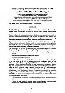
Introduction Distance education, or distributed learning, has finally acquired general support from most circles. More than a hundred countries have built distance universities. Most campus universities are developing distance education units or courses. All major companies are building training Intranets for their personnel. An eLearning industry has developed to provide eLearning tools and services. At the turn of the century, distributed learning had appeared to be an indispensable solution to the exponential growth of information in the knowledge society and for the support of new cognitive and learning activities it demands from individual and organizations. The extremely rapid spread of the Internet has accelerated this movement. The concept of a virtual campus, resting on the networking of actors and resources much more diversified than in the past, has become prevalent. These resources or learning objects include not only multimedia or Web-based documents, but also learning scenarios and persons to interact with: instructors and tutors, subject-matter experts, training managers, and professors acting as designers. LICEF, founded in 1992 as Télé-université’s research center adopted right from the start, the many dimensions of a Virtual Campus Model as its unifying research orientation [1]. The first research efforts provided insights on specific applications of multimedia telecommunications in distance learning. The Virtual Learning Center (VLC) model and architecture has been identifies as the central parts of the virtual campus. Within a VLC, five theoretical actors were then identified: learners, trainers, content experts, designers, and managers. Sixty-three roles have been defined for these actors, each one being a set of use cases. Then, for some of these roles, we have build object oriented graphs to design or reuse tools to be integrated in a VLC. In 1997, the Virtual Campus has become a powerful integrative concept at Télé-université and elsewhere. An ambitious five-year plan was supported by the Ministry of Education to transform the 23-year old distance university into a virtual campus based on a merge of hypermedia and telecommunications technologies. At the same time we had decided to re-implement the VLC architecture on a web-based 1
platform. In 1999, we had achieved the Explor@ implementation [2] and we had started using it to develop and deliver telelearning courses and environments at Télé-université and other institutions. Since the turn of the century, a rapid evolution has occurred marked by the convergence of three main movements. First, we are in the midst of the evolution towards a new generation of the Internet based on services oriented system and the semantic Web. Second, an international standardization movement in the field of eLearning has gained momentum, particularly on the concept of learning object repositories. Third, a growing emphasis on the use of Web portals as the main information and knowledge exchange media has provided more flexible learning environments than the first generation of LCMSs. Taking in account this evolution we have conducted work in the last three years on two fronts: implementing a new VLC system at Télé-université called Concept@, based on Web-based learning portals, and launching a new R&D program, within the LORNET1 pan-canadian research network, aiming to develop TELOS, a new generation for a Virtual Campus support system. In this chapter, the first section will revisit our initial Virtual Learning Center model, its actors, their activities, resources and delivery models to underline its strengths and identify its limits. The second section will focus on new vision and on orientation principles taking in account recent evolutions in the field of Web-based learning. The third section will present the conceptual framework of the TELOS system, its main services and its conceptual ontology. The fourth section will summarize the technical architecture of the system as it is actually being developed within the LORNET project. The fifth section will present some use cases that can already be supported by the system, to show some of its possibilities. A concluding section will discuss our hopes and prospects for this new Virtual Campus Model.
1. Revisiting Virtual Campus Models We will first summarize the Virtual Campus model that we have developed at the LICEF research Center in the mid-nineties. Then we will compare this achievement with the evolution that has occurred since then. Finally, we will identify why a new Virtual Campus Model is needed. 1.1. A first virtual campus model At the end of the nineties, some mega trends became prevalent. The exponential growth of information and the management of knowledge, the ubiquity of the Internet for the delivery of multimedia material, the emphasis on the acquisition higher-order skills and new collaborative learning paradigms, all leading to the advent of various form of telelearning or distributed learning. Behind terms like “distance education”, “online learning”, “telelearning” and “multimedia training”, is a multi-facetted reality from which we can identify the following delivery models. “High-tech” Classrooms group students and trainers in a single location, together with sophisticated multimedia and network equipment. Networked computers can give access to web sites, internet multimedia presentation as well as videoconferencing with the outside world. Many universities and organizations build electronic campuses on this model, to help manage the many possible transitions from a predominant classroom presentation model to more interactive and flexible ways to learn and teach. Distributed Classrooms are quite similar, close to the fact that learners and trainers are in two or more distant locations. Learning events use generally specialized and sometimes costly, real-time videoconferencing system. Alternatively, desktop multi-point videoconferencing software can be used.
1
LORNET is a pan-canadian research network, a five year project aiming to developed eLearning and knowledge-based technologies for the Semantic Web.
2
Both of these first two models are close to traditional classroom teaching, some would say with more hype but not many pedagogical gain. Hypermedia self-training on the Web or CD-ROM gives preference to an individualized learning approach to Education. In the “pure” model, there is neither trainer nor collaboration between learners in the system. A training manager supplies learning resources: self-training modules, interactive or passive Web sites, multimedia material on CD-ROM or DVD. The main benefit of this model is to enable the learner to progress at her own pace, wherever she is and whenever she chooses. Asynchronous “online” training departs from this individualistic view. It is organized and led by a trainer or a teacher, priming interaction with the learners or between learners for team work and discussion groups. Unlike the above classroom like models, these interactions are asynchronous, retaining some of the flexibility of self-training, with the exception that the pace between modules is decided upon by the teacher. The main tools and activities are forums, email, FTP transfer, together with less frequent audio or videoconferencing, online presentations, and real-time collaborative activities. Communities of Practice focus on a professional task. The learners are basically content expert trying to extend their knowledge through the asynchronous exchange of information via forums, email, or document transfer. They progress through team problem solving and know-how sharing around projects. Unlike the previous model, there is no trainer acting as a content expert or pedagogical coach, but a group animator that possesses less knowledge in the subject matter than the learners, but more knowledge of methods to support group interaction. Performance Support Systems integrate training even more closely to the actual work process and tasks in an organization. Extensive use of the organization’s data banks and support software are made both ways: to use training material to help job performance and also to use real problems and tools to support training at and outside the job. online help, adviser systems, human supervisors are supporting these training – working activities. This model promotes just-in-time information to help the user focus, alone or in teams, on real-life situated problems. We decided to design a Virtual Campus model that could encompass any mix of these eLearning delivery methods, in particular to integrate the best features of the last four models. Actors in a Virtual Campus In this Virtual Campus model, we have identified five categories of actors. Each actor is personified by different persons or digitized agents playing a variety of roles and relying on a variety of resources, documents, communication, and production tools. Figure 1 present the main interactions between these actors2. There is a basic cycle where an Informer, responsible for the information process, investigates the structured body of knowledge in a domain to make available new information to the learner. The learner, ruling the learning process, transforms this information into personal knowledge. The other three actors, acting as facilitators, support this basic process in different ways. The Designer constructs the learning environment, in particular the learning scenarios. The Trainer is pedagogical adviser, mainly coaching the learner according to the learning scenarios. The Manager, organizes groups and events with respect to the learning scenarios and is also an adviser on any organizational issues. 2
The letters on the links have the following meanings: an R link between an actor, represented as an hexagon, and a process represented as an oval, means that the actor is responsible for the process; an I/P link between a resource represented as a rectangle, and a process either means that the resource is produced by the process or is an input to the process; an S link means that a class of actors is a sub-class of a larger class. These conventions follow those of the MOT knowledge modeling technique [3, 4] we have developed during the nineties.
3
_______ _
_ _ _ _ Þ ß à á â áã ß ã ä å
Figure 1: Actors and main telelearning process Interaction spaces and resources Each actor, depending on the delivery model and other factors, needs resources that are distributed in interaction spaces. Table 1 presents a resource distribution into five spaces for a learner. A similar distribution would be made for a trainer’s or a designer’s environment. Table 1: Example of resources distribution in an learner’s environment
4
Each interaction space offers resources grouped according to a major function in the environment: selfmanagement of the telelearning system, information access, production of new information, collaboration and communication with other learners (or similar actors), and assistance from other facilitators such as trainers, informers, managers or designers or from computer agents or help files. Figure 2 presents the user interface for a learner environment in the Explor@ implementation. Environments for other actors would be similar.
Figure 2: A course website and the resources in an actor’s environment The first two windows enable a user to enter an organization’s Web site and choose a course and a role. The next two windows are the course entry page and the environment window. This last window provides a set of menus giving access to interaction spaces into which the resources are available whether they are multimedia document, communication or self-management tools or access to persons to interact with. These resources are classified in a number of interaction spaces such as the ones in table 1 1.2. The Explor@ Implementation of the Virtual Campus Model Figure 3 presents a conceptual view of the architecture of the Explor@ system. The system deals with four types of objects: actors (or roles), learning objects (or resources), knowledge and competency, and operations/activity structures (or functions). Actors operate functions composed of operations (or activities) where learning objects are used or produced. Knowledge and competencies describe the information owned, produced or processed by actors, processed in operations or contained in resources. Four corresponding managers store and retrieve information in a database, construct information structures and display information to users.
5
* Services
* 1
Materials
1
* 1 Events
Tools
1
Use and produce «subsystem» Resource Manager
*
Learning Objects
Operation Structures
Reference
Rule
«subsystem» Operations Manager
Reference «subsystem» Knowledge Manager
Knowledge and comptencies
Actors
Facilitators
«subsystem» User Manager
Others Learners
Figure 3: High Level Architecture of the Explor@-2 System 1.3. Values and Limits of the Explor@ Implementation of the Virtual Campus Model The Explor@ system, based on this Virtual Campus Model was put in operation in 1999. Compared to distance learning platforms or Learning Content Management System (LCMS) as they were beginning to emerge, it had a number of innovative features. •
Explor@ operated on basic main data structure structures, an activity or operation structure and a knowledge and competency structure, unlike most LCMS that provides only an activity structure. The activity structure decomposes a course or a learning program into modules and units-oflearning, down to terminal activities. The knowledge and competency structure describes the structure of subject matter to be learnt. The association between the two structures helps learners and facilitators to target learning objectives, to obtain or provide assistance, and to evaluate the learners’ progress towards these objectives.
•
Explor@ was build around a resource aggregation paradigm and reusability principle (the term “learning object” was not used at the time but the idea is the same), making it possible to assemble a set of educational support tools and resources to be reused across programs, courses or activities delivered by an organization and more generally on a international scale. In 2002, a learning object manager based on the LOM was added to the Explor@ tool set.
•
The system had no limitation on the number of actors, adding more flexibility compared to the traditional learner-trainer-manager trio found in most LCMSs. In one application for a lawyer’s training program, we had to design seven kinds of actors with each a different environment.
6
•
Each course could be designed to meet different needs implementing different pedagogical approaches, by using a variety of proprietary or third-party tools, made available to learners, course designers and other facilitators, such as instructors, content experts (informers), training program administrators, etc.
•
An Advisor Editor, enabled the designers to build a set of rules that would trigger help/assistance in various forms (questions, messages, visual cues) on user demand or when certain conditions were met by values in the user properties tracked by the system.
•
Explor@ was designed to support the integration of existing Web sites without changing their format, thus allowing an organization to transform its training/learning methods progressively. For example, one could take a Museum Web site and use Explor@ to add learning scenarios, documents, communication tools and other resources very easily, without changing the Web site.
•
Finally, the open modular structure of the system made it possible to significantly reduce design time, speeding up the implementation and allowing periodic updates by the design team or the online tutor. Environment maintenance also became much easier. Once the first course was implemented, each additional course integrated into Explor@ could be limited to a few Web pages and hyperlinks to existing documents.
Despite these interesting features, Explor@ has some important limitations that explain why its use was finally more limited than we expected. First, it is not totally Web-based requiring the installation of the Java virtual machine on the client, which created some deployment difficulties for novice users. Furthermore, the system is not multiplatform. It works well only on the Windows operating system and many times, adaptation had to be made when a new version of the operating system or a new Web browser became available. On another dimension, the multi-actor capability is incomplete; each actor has his own environment but joint interfaces are not available which makes it difficult to play some multiactor scenarios built with the IMS-LD specification for example. Also the transfer from the design environment to the delivery actors’ environments has to be made manually. Finally, there is limited interoperability with other systems even though some SCORM export and import functionalities have been introduced. These technical limitations to Explor@ could be mostly removed using recent advances in software engineering and eLearning standards, while keeping most of its conceptual virtual campus model. At Téléuniversité, we have used DotNetNuke as a portal generation kernel and we have integrated to it the main modules of the Explor@ system through the use of Web services. This has led to CONCEPT@, the new platform that is actually replacing Explor@ and other home-made eLearning systems as the institutional tool to generate portals for designers, for learners and for tutors at Télé-université. An interesting feature of the new architecture is that it is layered, that is a design portal is assembled and used to generate specific portals for a program or for a course.
2. Vision and Orientation for a New Virtual Campus Model At the turn of the century, new set of concepts began to emerge from different fields such as Web-based layered learning portals, service oriented frameworks, model-driven or ontology-driven architectures and multi-actor scenarios and workflows on which we have based a new Virtual Campus model, despite the technical improvements from Explor@ to Concept@. We will discuss briefly each of these developments and then present the vision and orientations of a new Virtual Campus model.
7
2.1 Major Innovations and Trends From LCMSs to Web-based learning portals. In the last 10 years hundreds of distance or e-learning platforms (or LCMSs) such as WebCT, BlackBoard, LearningSpace, Docent, Moodle have been used to deliver learning on-line. Recent reviews of e-learning platforms show that there are not great differences between them. Most platforms are mostly designed for a limited set of predefined actors (author, trainer, learner). They are focused on a limited array of pedagogical and delivery models for self-training and online asynchronous conferencing. Their efficiency as quick authoring tools for the web is often achieved by reducing drastically the variety of instructional strategies, each course having similar structures and components. The advent of learning portals and Web services presents an interesting evolution towards more flexibility, towards another vision of learning than just giving access to a predefined, preformatted and pre-digested content. Learning portals promote learning models where activities emerge such as in project-based learning New open source tools like DotNetNuke based or Uportal have been made available to help construct course, program or even institutional portals more easily than before. One level up: aggregating custom-made platforms. Compared to the evolution of generic software (text editors, spreadsheets, etc.), e-learning systems are now in a similar position than the integrated software of the last decade where text, spreadsheets and database editors could transfer data only within the integrated suite. Similarly, eLearning platforms offer a set of wired-in tools that are difficult to interoperate with tools from other platforms. Just as integrated suites of generic software have been replaced by integration mechanisms at the operating system level, we aim to design TELOS on the same interoperability principles. The new Virtual Campus model for TELOS will extend the portal assembly mechanisms to enable technologist to built their own platforms (or eLearning desktops) in a variety of distributed learning environments or models such as electronic performance support systems (EPSS) integrated in a workplace activity, communities of practice, formal on-line training and technology-based classroom, and different forms of blended learning or knowledge management platforms. Service-oriented frameworks [5] are rapidly gaining popularity with the wide adoption of Web Services, and because of the lower costs of integration coupled with flexibility and simplification of software configurations. For example, a student record system may expose services defining student enrolment and registration processes and related information, which can then be used by a learning management or a library system. A framework creates a broad vocabulary (an ontology) that is used to model recurring concepts and integration environments and is equivalent to the concept of a pattern in the software development community. One of the primary goals of a service-oriented framework is to encourage “coherent diversity”, by providing alternate service definitions which can then be used to meet the diverse goals of the organisation. An interesting aspect of a service-oriented Framework is, for each identified service, to be able to reference one or more open specifications or standards that can be used in the implementation of the Service, for example the IEEE-LOM for resource referencing services or IMS-LD for multi-actor learning scenario composition services. This is the case of ELF, the eLearning Framework [26], which is a service-oriented factoring of the core services required to support e-Learning applications, portals and other user agents. Each service defined by the Framework is envisaged as being provided as a networked service within an organization, typically using either Web Services or a REST-style HTTP protocol. Another example is the Open Knowledge Initiative (OKI) [27], which specifies a system architecture by identifying a set of services upon which learning tool developers can base their work. OKI is taking a layered approach defining clean boundaries between a layer of common services and an upper layer of educational service, each services made through an API to help integrate applications. The TELOS conceptual framework, which will be presented in section 3, has also been designed as a service oriented framework, to facilitate the aggregation of services in order to create custom-made platforms and eLearning and Knowledge Management applications. 8
Model-driven, ontology-driven architectures. Model-driven architectures involve three types of models: a platform independent model (PIM), a platform specific model (PSM), and a Code model [8]. The main gain is the generation of the code from the model in successive layers, the model being reusable in other context with few adaptations. Ontology-driven architectures [6, 7] add to this paradigm an explicit ontology structuring of the objects processed by the system, acting as its executable blueprint. They therefore tend to maximize the PIM and minimize the PSM and Code models. This programming style follows a pattern analogous to the Prolog programming language. Here the declarative part is encoded in the ontology, in our case through OWL-DL statements that are similar to Prolog statements. The execution part is encoded in parameterized queries prepared for an inference engine that will process the queries, the result of the query being events that trigger the execution of one of the services. In the TELOS software development process, this strategy is used to cover the most fundamental elements of the core. Multi-actor learning designs and workflows. We have pointed out earlier some weaknesses of our first Virtual Campus model. All kinds of actors can have their specific environment but these environments are each mono-actors. This question is now solved partly in workflows modelling languages such as BPMN, the Business Process Modeling Notation [18] and in a eLearning design specifications like IMS-LD [16]. Some instructional design graphic software such as LAMS, and our own MISA scenarios using the MOT graphic editor are able to represent multi-actor scenarios of workflows. Unfortunately, these representations are either informal like LAMS, semi-formal like MOT, or they are incomplete for learning design modeling, such as BPMM Workflow models. Multi-actor learning designs and workflows provide a central aggregation mechanism grouping actors, the operation they perform and the resources they use or produce from or for other actors. The notion of a multi-actor scenario is a central piece of the new Virtual Architecture model and its TELOS implementation [9, 10]. 2.2 Orientation Principles Here we present the main orientation principles [11] that lead the development of the architecture of the TELOS system. Solving Real Learning and Knowledge Management Problems. The TELOS system aims at facilitating learning and knowledge management activities. This entails the need to examine real educational and knowledge management problems, to analyze them thoroughly and to provide solutions to real user problems, not only in terms of system’s tools, but also in terms of processes to use them effectively in real contexts. We must avoid being technologically driven instead of solution-driven, so the driving force is the careful definition of use cases that guides the design of the architecture and the development of the system. Reusing and Integrating Existing and New Tools. LORNET is an oriented research project aiming to integrate technologies from different fields and to develop new ones when they are educationally significant. We reuse, as much as we can, existing editors, communication tools, interoperability protocols and specification from norms and standards international bodies, guided by uses cases that underline the need for new tools or new ways to assemble or extend them. In these activities, we focus on specific TELOS core components that facilitate the reuse of existing tools by their users. Concentrate on Essential Developments - Reduce risks. The goal of the architecture is to reduce the risks by shifting the accent from tool development to careful analysis, evaluation and well-planned specification. This will enable the TELOS team to focus on essential developments, and leave more costly development or adaptation to industrial, university or public partners in the network. Flexible and Pragmatic Aggregation. Pragmatic aggregation means a convergence of technological means and human interventions or interactions to achieve certain goals. So the system should have enough flexibility to be used in a variety of situation, from formal well-planned instruction, to more or less
9
structured self-training, emerging communities of practice or performance support systems integrated with work environments. The success of TELOS will come from its demonstrated utility in a diversity of situations. A Society of Human and Computer Agents. Software engineering sometimes sees the “system” to be solely composed of software components separated form their users. At the opposite, we adopt a multi-agent view where human and computer agents are interacting components of the system, providing services to each other. Extending the “Human-in-the-loop” we recognize that sometimes, organizational adaptations, advising, documentation support or human communication activities can be more appropriate (and less costly) than building new tools. This approach also favors maximal results with realistic efforts. Build Technology-Independent Models. The important work involved in the TELOS system should survive the rapid updating pace of technologies in general. At the start, it enable TELOS to operate on different, network, hardware and operating system configurations, and to integrate it with other learning or knowledge management systems. The architecture is built to protect the conceptual models from technological instability. The conceptual specifications are kept separate from any implementation. The TELOS system should then be able to reuse such “conceptual programs” despite different previous technology environment, and adapt it to new technological implementations. So the conceptual models are not just prerequisite to building the TELOS system; they are part of the system, as one of its most fundamental layer. Learning Ecosystem Models for Planning, Support and Evaluation. Most distributed learning systems today do not have a model of the processes, the users, the operations and the resources that they intend to support. Besides direct support for learning and knowledge management tasks, we aim to introduce tools to model the complex processes involved in a distributed learning system, before its use (to design it), during its use (to support users and observe their behavior) and after its use (to evaluate and maintain the system). These modeling components and tools are built-in features of the TELOS system. They aim to enable users to interact efficiently in pre-planned, as well as emerging and user-controlled events where the initial environment is transformed, thus implementing a “learning ecosystem” approach. Modularization and Layer Independence. The very flexible system envisioned will amount to a very small kernel, at a very high level of abstraction, capable of assembling services that generally form the core of a system, for example functions like learning object aggregations, component coordination and control, ontology-based indexation and search, scenario modeling and so on. The architecture will promote horizontal modularity: horizontally between components, and vertical layer independence from an abstract representation, to a concrete implementation, to a run-time version of TELOS applications. Construct Reusable and Interchangeable Models and Components. TELOS being model-oriented, it then becomes possible to implement the model components in various forms and alternative tools, classified by their functionalities and grouped in interoperable classes. TELOS then appears as a flexible assembly system enabling the integration of tools, already existing or to be produced, by various groups, to support a variety of learning and knowledge management models. Even at the kernel level, the general functions could be covered by one or more alternative “kernel” modules, accessible on a service bus for selection by system configurators and designers. An Assembly and Coordination System. The TELOS kernel will then be mainly a set of computer agents capable to play parts of “TELOS scripts”, using alternative compilers or interpreters within different operating systems. TELOS will not be another huge distributed learning platform or a system to generate rigid platforms, even though it can assemble components specific to some intended set of applications. The term “TEleLearning Operating System” should be seen as a metaphor. TELOS is planned essentially as a set of coordination and synchronization functionalities supporting the interactions of persons and computerized resources that compose a learning or knowledge management system. 10
2.3 System’s Levels and Main Actors Figure 4 shows a cascade of more and more specific system levels and their corresponding actors. The TELOS core is managed, adapted, extended by system engineers. With it, technologists in different organisations produce one or more TELOS Learning and Knowledge Management System (LKMS), each generalizing the idea of an “on-line platform” adapted to an organization’s particular needs. Unlike the present situations, each platform is extensible, and its components are reusable in other platforms. With a TELOS LKMS, designers can create, produce, deliver and maintain a number of Learning and Knowledge Management Applications (LKMAs), that is courses, learning events, knowledge management portals, etc. The LKMS is a platform for the aggregation of resources, activities and actors. Each LKMA, composed using a LKMS, groups one or more actor-specific aggregates called Learning and Knowledge Management Environments (LKMEs) intended for certain types of learners and facilitators: content experts, coaches, tutors, evaluators, managers, etc. An LKME is an aggregate of documents, tools, services, operations (activities) and actor agents. Before delivery, an LKMA and its different LKMEs are instantiated by an actor called an application administrator to start a new session involving a group of participants. Using these instances, the participants produce results that are resources and outcomes called Learning and Knowledge Management Products (LKMP) which are stored in a database for reuse or adaptive support.
Figure 4: Four-level Cascade of Systems and Products The roles played by a person are interchangeable. Some persons acting as learners or facilitators can also be their own designers, and their own technologists or even engineers. Conversely, persons building environment can also be facilitators to designers. The interchange of roles can be provided by software role agents providing an interface between a human or system actor and the functionalities and data needed to achieve that role. Also some of the roles can be played by software agents, for example an intelligent advisor agent or a peer help or resource finder acting as a facilitator.
3. A Virtual Campus Framework and an Ontology for TELOS In this section we present a conceptual framework [12] for a new virtual campus model. We first present the main operations and actors in the model. Then, we identify a service-oriented framework to support 11
these operations. Finally, the model takes the form of an ontology that will expand into the TELOS technical ontology that is the main core element of the TELOS system. 3.1 Main operations and actors in the Virtual Campus model On figure 5, we present the more general use cases of the Virutal Campus model. A TELOS user (or a team of users), possibly helped by a facilitator providing assistance services, takes the responsibility to perform a TELOS operation. In this operation, users and facilitators use or modify resources in the TELOS Core and produce new resources that sometimes are embedded or referenced in the TELOS Core.
Figure 5: TELOS main operations, actors and resources Every time a user performs an operation, his/her previous knowledge and competencies are changed to new ones, which is the essence of learning by doing and doing by learning. In the TELOS system, it is possible to represent explicitly knowledge and evolving competencies related to the resources (persons, operations, documents and tools) using one or more semantic referentials. Semantic referentials can take the form of standard or specific metadata, classifications, taxonomies, thesauri or ontologies. In TELOS the operations are driven (or at least initiated) by human actors through some user-interfaces and mediated by computer programs, and sometimes by software actors. There are three basic groups of operations depending on their level of granularity.
12
• •
•
Basic operations on a resource consist of asking or delivering a service using a resource either directly, or indirectly, mediated through a resource provided by the system. Resource life cycle operations consist of a series of four sub-operations (phases) where a resource is composed, managed (prepared) for use, used in some activity, and analyzed, providing feedback to start, if necessary, a new resource life cycle. These operations are generally performed in sequence by corresponding actors called respectively composers, administrators, explorers (resource users) and facilitators (acting as analysts to provide assistance and feedback). System generation cascade operations are even more global. They consist of using the TELOS Core to produce a platform, technically called an LKMS: Learning and Knowledge Management System, designing with it one or more LKMA, Learning and Knowledge Management Applications (courses, learning events, knowledge management environments) and finally, using these applications to learn and to produce results grouped in a portfolio or LKMP: Learning and Knowledge Management Products.
The combination of the resource life cycle and the system generation cascade operations are shown on figure 6.
Figure 6: Resource life cycle and system cascade actors Figure 6 shows that the resource life cycles apply to each of the four levels of systems or products: Core, LKMS, LKMA and LKMP. At level IV, the TELOS core is managed, adapted, extended by actors called engineers. It is instantiated and prepared for use by a Core administrator, used by a technologist to build a LKMS, and analyzed by a Core facilitator to provide assistance and feedback to the other three actors of the Core life cycle. An analogous life cycle happens at level III where this time, the technologist is the composer of the LKMS and the designer is the user, helped by a LKMS or platform administrator and a facilitator. At level II, the designer is the composer of a LKMA and the learner a user, again helped by a
13
LKMA administrator and a facilitator. Finally, at level , within a LKMA, the composer and users are learner that produce and use resources and outcomes grouped in a LKMP. We can use different metaphors to describe these general processes. In a manufacturing metaphor, the resource life cycle corresponds to a process where a product passes through different productions operations. For the system generation cascade, the TELOS Core is like a factory that produces machine components or complete machines; the products of this first factory are used to build machines that will be used in other factories (LKMSs) to build cars, aircrafts, etc. (LKMAs), which are used by end users to produce an outcome (e.g. to travel). Using a biological metaphor, a simple operation corresponds to a life moment of an organism; a resource life cycle is an ontogenesis, the process of an individual organism growing from a simple to a more complex level. Finally, a system generation cascade is similar to the evolution of life, a process that generates new organisms from parents. These images are important to understand the role of the TELOS Core within an evolving TELOS system. As a manufacture, the TELOS Core itself starts with a complete set of components to produce LKMS factories, but it will also be open to improvement, adding new processes and operations, to produce more versatile machines. 3.2 A Service-oriented framework for the Virtual Campus model From an elaborated set of use cases, we were able to design a service-oriented framework for the new Virtual Campus model, bringing it closer to a possible implementation. Figure 7 present the main classes of services, each being explained in [12, 10] •
•
•
•
Kernel Communication services. The Virtual Campus model is a distributed architecture on the Internet. To become a node in the Virtual Campus, each user installs a kernel on his machine that provides basic communication services with other nodes where resources are distributed. These services include for example a service registry, the location of resources on the nodes of the network, connectors to provide communication with resources built with different technologies, protocol translation and so on. Resource interfacing services .Basic resources are documents in a variety of media formats, tools to process documents, operations that can be applied to other resources and finally persons interacting on the network. All these resources usually will required to be interfaced in different way (by a communication agent for format translation, through encapsulation for tracing, etc.) in order to be reached and to participate in the learning and/or knowledge management processes Resource life cycle services. These services provide a number of editors for a composer to build, adapt and aggregate resources, thus producing a model of the resource. This model needs to be managed by an administrator before the instances can be explored by a user and later on analyzed for assistance and feedback by a facilitator. Aggregates management services. These services provide management functionalities for the main aggregates (or Web portals) used in the Virtual Campus: Core, LKMSs, LKMAs and LKMPs portals. For example, they will help in the storage, modification, display, evolution and maintenance of versions of Core, the interoperability between platforms (LKMSs), the management of courses (LKMAs) and the LKMPs such as Portfolios.
14
Figure 7: The Virtual Campus Service Oriented Framework •
•
Semantic services. The services enable users to query or edit semantic resources, for example ontologies or metadata, and to create semantic referentials to be used to reference resources Resource publication services enable users to package resources with their semantic references, enabling various kind of resource search, retrieval and launching. With these services a user can call upon federated or harvested search operations to jointly display documents, tools, operations (including activities and units-of-learning) related to some domain knowledge and competencies. Common services. We have grouped in this category all the lower level services that are called by the services in the preceding category. They correspond to operations that all the actors need to make or called upon while participating in the Virtual Campus.
3.3 The Virtual Campus model as an ontology An important goal is to embed in the system technology-independent models, to help the system survive the rapid pace of technology evolution. For that purpose, the conceptual specifications of TELOS, expressed as ontologies should not be kept separate from their possible implementation. The TELOS system should be able to reuse ontologies as “conceptual programs”. In this vision, the conceptual models are not just prerequisite to the construction of the TELOS system; they are part of the system, as one of its most fundamental layer. These considerations motivated the need for an ontology-driven architecture (ODA) 0 combined with a Service Oriented Architecture SOA which also promotes the use of many international standards like OWL, IMS-LD, XPDL, SOAP, LOM, SWRL and RuleML. We have translated the use cases and the service-oriented framework of the Virtual Campus model into an OWL-DL ontology. We have selected to use OWL-DL ontologies [13] for TELOS applications for a number or reasons. It is one of the three ontology Web languages that are part of the growing set of World Wide Web consortium recommendations related to the Semantic Web. Of these three languages, OWL15
DL has a wide expressivity and its foundation in Description Logic guarantees its computational completeness and decidability. Description Logic [14] is an important knowledge representation formalism unifying and giving a logical basis to the well known traditions of frame-based systems, semantic networks, object-Oriented representations, semantic data models, and formal specification systems. It thus provides an interesting logical framework to represent knowledge. On a more practical side, a growing number of software tools have been designed to process OWL-DL XML files and to put inference engines at work to query the ontology in order to execute processes in a system. Figure 8 presents a part of the conceptual ontology for the Virtual Campus model. The first graph presents the three main categories of objects, that is Actors (Users and Handlers) that perform Operations, which use and produce Resources. Operations and Actors are also TELOS Resources (as shown by the S links). This graph is built using the graphic symbols of the MOT+OWL software that covers all OWL-DL primitives. This software translates graphs into standard OWL-DL XML files.
Figure 8: Part of the Virtual Campus Conceptual Ontology
16
Each of these classes of objects are further defined in sub-models that present their classifications and their properties. The second graph of figure 8 shows the taxonomy of operations that correspond to services in the service-oriented framework [15] shown on figure 7. In the following section, we explain how this ontology was revised and expanded to build the TELOS technical ontology, a central part of the implementation of the new Virtual Campus model.
4. The TELOS Software Architecture In the present section, we give a high-level overview of the software architecture. First, let’s look at a simple picture showing the coordination of the basic concepts of the Virtual Campus model inside a given TELOS node.
Figure 9: The "Global Picture" of a TELOS node We see in Figure 9 the TELOS Core which is the central controller of a TELOS system. The Core contains the TELOS Kernel basic communication services, the resources organized in libraries, the semantic layer, the local bus, the global bus and the runtime environment. The resources are the persistent data of the TELOS node. They can be users, multimedia files, software components, learning objects or aggregations of other resources created by users. This last type of resources is of a very important nature. It enables users to create new eLearning tools by gluing existing software components. It also enables users to model collaborative workflows describing knowledge, processes and practices in work processes or learning scenarios. The semantic layer is where all TELOS concepts are declared are related together through logical constraints. It defines the global behavior of TELOS. The semantic layer also contains the domain ontologies created by users that later permits semantic classification of the resources involved in the resource libraries using semantic descriptors, that is metadata records describing resources according to the domain ontologies of the system. The semantic layer is the foundational element of the ODA (Ontology Driven Architecture) behind TELOS. The TELOS runtime contains the running instances of the resources that need some temporary data persistency like software components and interactive learning objects. This runtime environment is connected to the core through the “Local Bus”. The Local Bus is the abstraction layer that let’s the core 17
speak to resources implemented in various standards and technologies using a uniform language: the Local Bus Protocol. This is a key element of the SOA (Service Oriented Architecture) of TELOS. It enables loosely coupled integrations of rich external resources like software components and web services. Finally the TELOS Global bus enables the interoperability between different TELOS nodes abstracting their particular physical platform and their network configuration. By connecting the Global Bus of many TELOS nodes we form a dynamic Peer-to-peer network. These networks may contain special nodes called community controllers which are basically centralized repositories for resources. 4.1 TELOS Aggregates and Scenarios We now explain one of the main principles behind TELOS: the aggregation of resources. Aggregation of resources is one of the most fundamental operations of TELOS. Roughly speaking, resource aggregation is about gluing some resources together to form resources of higher complexity. This can mean for example: build a content package from SCO’s (shareable content objects, learning objects), build a specific tool from individual software components, build an LKMS from tools and interfaces, build an orchestration incorporating users and tasks, etc. The aggregates can be roughly classified into three categories: collections, integrations and orchestrations. The software architecture has a unique formalism for describing all those types of aggregations. This is achieved with the specification of a unique XML format capable of representing all types of aggregates. This format is called XCAL 0. The basic structure of the XCAL language is the structure of “hierarchical directed graphs”. This means that an XCAL file describes nested directed graphs (each node of a graph can contain a graph) with vertices possibly starting and ending at various graphs levels. This mathematical structure has a very generic nature and can be used to model a wide variety of things: knowledge, processes, aggregates, … Using this generic structure as the basic aggregates format gives us a guarantee of the persistence of the format through its various usages. The most common and general type of aggregates found in TELOS are Scenarios. The concept of Scenario in TELOS is a formalism to represent multi-actors human/machine processes. Scenarios provide a high-level programming language for TELOS. This language is designed to be accessible to all TELOS actors including students, workers, teachers, designers, technologists and programmers. This goal is achieved by materializing the language through an intuitive visual syntax. For that, we use the graphical formalism of hierarchical directed graphs. This enables both “top-down” and “bottom-up” approaches to scenario modeling. We now look at the environment used to define and maintain scenarios: the Scenario Editor. To provide a basis to build a scenario editor for the TELOS system, conceptual work on function maps has been defined as a central piece of the TELOS architecture. We have developed a generic graph editor that can be used to define specific graph editors through a meta-model. These meta-models are materialized as ontologies in OWL-DL format. Then a comparative analysis has been made between business workflows, IMS-LD learning designs and function maps 0, identifying the most frequent 21 control situations for workflows encountered in software engineering literature 0. The MOT+LD editor 0, a graphic editor for IMS-LD, itself a specialization of the MOT graphic knowledge representation language 0 that has been evolved to suit our purpose. The Scenario Editor aims to generalize both IMS-LD and business workflows. The graphs produced by this editor are executable through a scenario execution engine called the Scenario Evaluator. The Scenario Evaluator will assure the coordination of actors in the enactment of the activities and the use/production of the aggregated resources at delivery time. 18
The Scenario editor uses four kinds of MOT objects with subtypes taken from the TELOS technical ontology [21]. These are shown on Figure 10. Concept symbols represent all kinds of resources: documents, tools, semantic resources, environments, actor resource, activity resources and datatypes. Procedure symbols represent scenario models (functions), human-based activities or software operations. Finally, principles are used both to represent different types of actors (as control human or software agents) and control conditions.
Figure 10: Scenario Editor Symbols Overview
On Figure 11, we can see an example of a simple scenario combining some of these visual symbols where a coordinator writes the plan of a Web site. Then three activities are performed by writers in parallel to write sections of the Web site. When these are terminated the flow of control is merged and a Web site assembling the different parts is built using a Web editor. Finally, this site is annotated semantically by the group.
Figure 11: A simple scenario model Unlike the actors, the control principles are embedded within the activity flow of the scenario model to decide upon the next activities. Figure 11 shows a general split condition after the first activity. After that, activities 1 to 3 are executed in parallel, based on the properties of the split condition object. Later on, the flow of activities merges through the merge condition object before activity “Assemble sections” takes control. This activity will wait for some or all the incoming flows to be activated before it is executed, again depending on the properties of the merge condition object.
19
Figure 12 shows another kind of condition that alters the flow of execution. In activity-2, if a timeevent condition is met (the activity has been going on for 30 minutes), the flow of control will not move to activity-3 but to activity-4 and continue, when it is completed, to activity-5. Properties of the event condition symbol will provide the details on the condition and action parts of the control principle to provide the execution engine with a clear formal definition of the processing to take place.
Figure 12: Event-based control
In the Scenario Editor, we see a combination of a control flow and a data flow. The control flow is modeled using the MOT basic P and R links. P links are used for the basic line of execution. R links identify at which activities an event will trigger a condition to alter the basic flow of control or identify the activities controlled by an actor. I/P links from MOT serve to model the data flow, either from resources to activities or operations where they are consulted, used or processed, or from activities or operations to product resources. This is why we need to distinguish between actors as active control entities and resource-actors that will serve as data provider or be products of an activity (e.g. a new person of software agent added in a system). A similar distinction is made for resource-activities that can be seen as resources to be transformed, for example by other activities creating or modifying their description. In TELOS, the scenario editor will enable engineers to combine resources into larger ones, technologist to built platform workflows for designers of learning or knowledge management environments, and designers to build course designs or work processes for end users. 4.2 Technological Backend Behind Scenario Enactment Scenarios are executed in the system through the Scenario Evaluator. The present section gives some technical details about scenarios and their execution. We also talk about what distinguishes scenarios from others kinds of process definition languages. Scenarios bring together the concepts of control-flow (omnipresent in business workflows e.g. BPEL, XPDL, BPMN), data-flow (present in scientific workflow languages e.g. 0), learning-design (IMS-LD type of languages) and ontologies. In terms of control-flow, scenarios actually support most of the classic patterns of control described in 0. We plan to cover all the patterns in a future release of the scenario evaluator The data-flow part exhibits all the features of a classic data-flow language and provides data semantic through a technical ontology. This enables modellers to describe explicitly the data-flow relations between the different processes involved in a scenario execution. Scenarios are inherently designed to coordinate distributed resources. These distributed resources include software components and web services each developed with possibily different technologies. The execution engine actually supports components written in C, C++, C#, Java, Scheme and all SOAP-based web services. Software components resources are connected through the TELOS Local Bus which assures both connectivity and modularity between the kernel and the components. Scenarios are persistent, interruptible, resumable and traceable. Finally, scenarios have the neat quality of being mobile. This means that instances of scenarios can migrate from one TELOS node to another while they are in execution. The key strategy is to translate XCAL aggregates generated by the Scenario Editor into networks of communicating processes. This means that all the nodes in the Scenario model will create a tiny process in 20
the TELOS runtime when a Scenario model gets instantiated. All those lightweight processes can communicate with each other with message passing. This means that all the processes instantiating a Scenario model have the ability to receive messages in a mailbox and propagate messages to other processes. The basic building block used to implement those process networks is Termite 0, an Open Source implementation of communicating sequential processes (CSP) in the Scheme language. Termite is itself inspired by Erlang 0. Using this basis, the implementation of the Scenario Evaluator has a very small footprint and is therefore highly customizable without tremendous efforts. 4.3 Semantic Referential Services The semantic layer is literally the backbone of the TELOS system. The central part of the semantic layer in TELOS is the TELOS Core Technical Ontology presented above. All the pieces of TELOS must fit in this blueprint of the system. The TELOS ontology is not only an external representation of the architecture of TELOS with all its components and functionalities. It is an internal way to drive TELOS processes through a coherent path insured at each step by the constraints contained in this ontology. TELOS Core Technical Ontology is the logical blueprint of TELOS. It is the TELOS “Program”. Here we put forward a software development strategy in which core functionalities are programmed in ontologies and in the queries we send to inference engines working with this ontology. We therefore introduce a logic programming paradigm at the very core of TELOS. In the above sense TELOS architecture is an Ontology Driven Architecture (ODA) [6]. This approach combines very well with the SOA (Service Oriented Architecture) we announced above. The TELOS semantic layer is the most fundamental module of the TELOS kernel. In fact, the very first steps of the TELOS boot process are directed towards setting up a fully operational semantic layer module so that other important modules of the system can rely on it. The main constituents of the TELOS Semantic Layer are displayed in figure 3. In it, we see that the Semantic Layer is basically a wrapper over an OWL inference engine. It therefore provides an API to the other modules of the system that transforms the API calls into queries to that inference engine. Due to the relative immaturity of OWL-DL inference engines, we decided to use the DIG protocol to communicate with the inference engine. This has the advantage of making us independent of any particular OWL inference engine.
Figure 13: Semantic Layer Overview
To boot the Semantic Layer, we must feed the attached inference engine with all the knowledge contained in the local TELOS node. This knowledge is all contained in the TELOS Core Technical Ontology. Using an ontology to support the whole system provides a flexible, yet logically sound foundation for formally describing the concepts of the TELOS System. Using description logic, we can define all the various TELOS concepts. Here we must clearly outline the fact that the TELOS Semantic Layer makes TELOS a very innovative system in its category. The usual trend for recent eLearning systems and information systems in general is to rely on relational databases (RDBMS) for the data persistency. The TELOS system takes a different path by proposing the formalism of description logic for data persistency.
21
The reader will note that this doesn’t exclude using RDBMS technologies underneath the semantic layer for optimization purposes. In fact many existing RDF triples stores take this approach. This innovation we propose for data persistency has many benefits. First, since we put it at the lowest level in the system architecture layers, it promotes all other system modules to rely on formal logic to implement their concepts. This has the consequence of providing a rich semantic integration of all the system concepts (users, operations, documents, processes, applications, workflows…). The most interesting benefit may be the flexibility of the resulting backbone. Ontologies can change and evolve over time. When using appropriate tools, one can work on the system backbone and alter it during runtime by changing the concepts definitions. Compared to the direct usage of RDBMS technologies, this is a very strong benefit. A relational database can be changed and restructured too, but generally at a high cost. The access to an inference engine that can prove or disprove any description logic proposition on the system is the next most obvious benefit. This conceptually outperforms the expressivity of any RDBMS query language.
5. Use Cases Realized with the TELOS actual prototype To illustrate some of the possibilities of this Virtual Campus Model and its TELOS implementation, we will now present three uses cases. These will take the form of three TELOS scenarios. These models can be termed “TELOS executable use cases”. The first one is built by an engineer to aggregate software components; the second one is built by a technologist to combine the design functionalities of more than one platforms, and the third one is used by a designer to build a multi-actor eLearning environment. 5.1 Aggregating components services In this first use case, an engineer aggregates components to compose a new service embedded in an operation called the “Batch LOM Extractor”. This operation takes a set of keywords, a number of LOM to find and the name of a destination folder in a repository of learning objects managed by the PALOMA software. On the right of figure 14, these three inputs are shown as resources. The aim of this aggregated operation is to search Google with the given keywords, datamine the resulting websites to extract LOMs, insert those LOMs into the requested PALOMA folder and to open this folder into the PALOMA software interface to show the results to the user. This operation combines the services of four components embedded in corresponding operations shown on figure 14. These operations are linked sequentially in the following order: 1. The Google Search Web Services takes keywords and the number of results as inputs and produces a structure containing Google’s search results. 2. For each URL that Google returns, an operation Extract DC Metadata visits the URL and extracts Dublin Core metadata automatically through natural language processing of the Web page. 3. Then this DC XML string is passed to a DC to LOM converter to produce a corresponding standard LOM XML, which is the format used by PALOMA. 4. Then, with this LOM XML and the name of a destination folder, the LOM is inserted in the PALOMA folder. 5. This cycle is repeated until all the LOMs are processed up to the number given initially; when this is finished, the PALOMA software is launched with the folder containing all the LOMs, enabling the display of LOM metadata and of the resource.
22
Figure 14: Engineer constructing an operation aggregating services What we see here is the aggregation of components built by different groups using different technologies. The Google Search Service is launched using a SOAP Web service connector provided by the TELOS kernel. The Metadata Extractor is a C# component linked to the TELOS kernel by a C# connector. The DC to LOM conversion is a Scheme component linked through a Scheme connector. PALOMA is a Java component linked through a Java connector. All four components have been previously integrated into TELOS libraries of resources with their semantic references to the technical ontology that are instances of some classes of resources. These semantic references describe in particular what kinds of inputs and outputs each service expects. Inputs and outputs are ports of the operation symbol. In the scenario graph, values are connected to these ports using U links. Also, the semantic references describe the technology used, so the proper connector is mobilized in the kernel to enable the execution of the component. The result is a new aggregated operation shown on the right of figure 14 with its three inputs. This new operation has been integrated in the TELOS library as a new digital resource. It has been referenced in the TELOS technical ontology so it is now ready to be aggregated with other resources, for example as a tool in an platform (LKMS) or an application (LKMA). 5.2 Building an eLearning platform The next use case example will show how a technologist can combine functionalities from different platforms to compose a new LKMS with greater capabilities. The central component of the combined platform is a process graph for the designer used as a design scenario to produce courses. This design scenario corresponds to the central tasks of the MISA instructional engineering method [2, 4]. Figure 15 shows part of this scenario that involves using Concept@, Télé-université’s actual course design platform, augmented with the TELOS scenario editor and other components. 23
Figure 15: Technologist constructing an augmented LKMS platform for designers The design scenario displayed on figure 15 in the TELOS scenario editor starts with two parallel functions performed by an LKMA designer: design of a course backbone using the Concept@ LCMS and development of a knowledge and competency model for the course using the TELOS ontology editor. Let us note that actually, Concept@ helps produce an activity tree representing the course plan with the subdivision of the course into modules and activities. This structure can be exported to a SCORM package. Many roles can be defined in Concept@ but this exceeds SCORM’s mono-actor capabilities. So information on roles/actors is lost when we open the corresponding graph in the TELOS scenario editor, after the SCORM output of Concept@ is handed to the TELOS operation that translates the course structure. The next design phase proceeds graphically in the scenario editor to add the actors designed in Concept@ manually which is not a big task. There, more advanced flow of control can be added to better personalize learning. Concept@ has no capabilities for knowledge and competency modeling so an external editor, the TELOS ontology editor has been integrated in the designer’s environment. With it, he can build an ontology to represent the subject matter and he can add to the main concepts some competency goals. These two main design tasks proceed in parallel up to a point when a relative stability is achieved. Lists of actors, activities and resources are then available from the scenario editor and a list of competency is produced by the knowledge/competency modeling branch. The rest of the scenario consists in associating target competencies and knowledge to resources, actors and activities using a competency distribution tool, searching for additional resource using a resource manager like PALOMA and using these associations to configure a learner evaluation tool that will be used during the delivery of the course. 24
In the little figure on the right of figure 15, we show a list of tools that will made available in the designer’s environment. Included are all the tools in the design scenario on the left, plus other tools that can be added by the designer himself. Once the design scenario is completed, with all functions described by sub-graphs down to terminal activities and operations, a designer’ Web portal will be produced automatically, grouping the tools in menus and providing the design scenario as a guideline for designers. 5.3 Designing an eLearning environment Following up a design scenario in a LKMS, a designer can construct course or knowledge management scenarios and environments. Figure 16 shows such a scenario which had first been design according to the IMS-LD specification, using our MOT+LD graphic editor [4]. The upper right window shows the global scenario model where the learning unit on the solar system is subdivided in four acts. The larger window shows the learning scenario for act 2.
Figure 16: Designer constructing a multi-actor scenario. This scenario displays two teams of learners, each using a chat and different input documents to discuss planet properties. When the internal team discussions are over, both teams and the teacher join in a forum discussion. The teacher observes, manages and moderates the discussion. He stops it at a certain point to start the act 3 sub-process where individual work will be done by the learners to find a solution to a matching problem between planets and some of their properties. Again, from this design, four different Web environments will be produced automatically for the teacher, for each team of learners, and for the whole group. This example shows the power and flexibility of TELOS designs. Similar designs can be applied as well to build multi-actor workflows for knowledge management activities in an organization.
25
6. Conclusion – Expected benefits for eLearning Environments. We have covered some key principles behind the new Virtual Campus model and its TELOS implementation. We suggest that using a low number of generic and flexible principles will make it possible to build complex yet easily manageable eLearning and Knowledge Management environments. We now summarize the benefits we expect from the extension of the former Virtual Campus model to the new one. 1. Global Systemic View. The Virtual Campus model takes a global view to provide cohesion to Virtual Campus activities. At the upper level, an institution can create a global workflow to coordinate the major processes where different categories of personnel interact to provide services to the students. At the next level, more specific workflows are designed and tools, documents and activities are orchestrated into a platform or a portal (LKMS). Then, within a portal, a number of learning scenarios (courses) or service workflows are designed as application (LKMA) portals. Finally each scenario or knowledge management flows is used by end users to produce results. 2. Extended set of actors. Compared to the actual LCMS in operation, and also to our initial VC model, the new global approach leads to an unlimited set of actors. At any level, in principle, any number of actors can be defined and supported. 3. Better process coordination. The fact that the system holds a model of the VC processes and support resources leads to better process coordination. Especially in distance universities, this provides better assurance that the quality of services will be maintained when the personnel changes, especially when it must provide products of his activities to other actors. 4. Visible scenarios and workflows. Learning scenarios or workflows can always be consulted in a Web portal interface, changes to components or actors can be seen right away. Each user taking an actor’s role can visually see the context of the activities he has to perform, what resources to use or produce and with whom he is to interact with. 5. Flexible and adaptable environments. Each environment operates according to a technical ontology representing the Virtual Campus model, which is part of the system. This enables very flexible and adaptable environments. If a new kind of actor, activity or resource needs to be introduced, this is done simply by modifying the ontology, without changing the main operations of the system. 6. Resource reusability is a goal pursued by many advocates of learning object repositories, but it is not that easy to achieve. Using ontologies to model each resource within the same framework, and adding connecting operations to take care of possible technology mismatches brings solutions to resource reusability problems. 7. System interoperability. With the new VC model, it is possible to bring different technologies and different platforms to work together. For example, a designer could built a course using a scenario editor in one platform, and transfer it to another platform to add new functionalities, for example personalized assistance. This process can be designed by defining the aggregation scenario between platforms and building ontology alignment operations. 8. Modeling for all. Modeling is not an easy task but it is important enough to be made accessible not only to engineers and technologists, but also to instructional designers, learners and trainers. User-friendly visual modeling languages are made available at all levels of the system. 9. Focus on learning and work designs. Finally, we hope the proposed approach to Virtual Campus modeling and operation will reduce the technology noise that is often present in eLearning applications when too much time is devoted to solving pure technology problems, instead of focusing on learning problems. We suggest that the activities will be more focused on pedagogy and quality of educational services. 26
These approaches offer new possibilities but also pose additional challenges. The TELOS project, a five year research project, is now past mid-term. Some considerable refinements will happen but our hope is that the results achieved in this project will lead the way to future developments.
References [1] Paquette, G. (1995) Modeling the virtual campus. in Innovating Adult Learning with Innovative Technologies (B. Collis and G. Davies Eds), Elsevier Science B.V., Amsterdam [2] Paquette, G. (2001) Designing virtual learning centers. In H. Adelsberger, B. Collis, J.P.E., ed.: Handbook on Information Technologies for Education & Training. International Handbook on Information Systems. Springer-Verlag 249–272 [3] Paquette G. (1996) La modélisation par objets typés: une méthode de représentation pour les systèmes d’apprentissage et d’aide à la tâche. Sciences et techniques éducatives, pp. 9-42, avril 1996 [4] Paquette, G. M.Léonard, K. Lundgren-Cayrol, S. Mihaila and D. Gareau : (2006) Learning Design based on Graphical Knowledge-Modeling , Journal of Educational technology and Society ET&S , Special issue on Learning Design, January 2006 and Proceedings of the UNFOLD-PROLEARN Joint Workshop, Valkenburh, The Netherlands, September 2005 on Current Research on IMS Learning Design. [5] Wilson, S., Blinco, K., Rehak, D.: Service-oriented frameworks: Modelling the infrastructure for the next generation of e-learning systems. White Paper presented at alt-i-lab 2004 (2004) [6] Tetlow, P., Pan, J., Oberle, D., Wallace, E., Uschold, M., Kendall, E.: Ontology driven architectures and potential uses of the semantic web in systems and softrware engineering. http://www.w3.org/2001/sw/BestPractices/SE/ODA/051126/ (2001) [7] Davies, J., van Harmelen, F., Fensel, D., eds.: Towards the Semantic Web: Ontology-driven Knowledge Management. John Wiley & Sons, Inc., New York, NY, USA (2002) [8] Kleppe, A. G., Warmer, J. B., & Bast, W. (2003). MDA explained : the model driven architecture : practice and promise. Boston: Addison-Wesley. [9] Paquette, G., Rosca, I.: Modeling the delivery physiology of distributed learning systems. Technology, Instruction, cognition and Learning 1-2 (2003) 183–209 [10] Rosca, I. (2005) TELOS Conceptual Architecture, version 0.5. LORNET Technical Documents, LICEF research centrer, Télé-université, Montreal, 2005 [11] Paquette, G., Rosca, I., Mihaila, S., Masmoudi, A.: Telos, a service-oriented framework to support learning and knowledge management. In Pierre, S., ed.: E-Learning Networked Environments and Architectures: a Knowledge Processing Perspective. Springer-Verlag (2006 in press) [12] Paquette, G., Rosca, I., Masmoudi, A., Mihaila, S.: Telos conceptual framework v0.8. Lornet technical documentation, Télé-Université (2005) [13] W3C (2004) OWL Overview Document (http://www.w3.org/TR/2004/REC-owl-features20040210/) [14] Baader, F., D. Calvanese, D.McGuinness, D. Nardi, P,Patel-Schneider, editors (2003) The Description Logic Handbook. Cambridge University Press.
27
[15] Paquette G. and Rogozan D. Primitives de représentation OWL-DL - Correspondance avec le langage graphique MOT+OWL et le langage des prédicats du premier ordre. TELOS documentation. LICEF Research Center. Montreal, Québec, 2006. [16] IMS-LD (2003). IMS Learning Design. Information Model, Best Practice and Implementation Guide, Binding document, Schemas. http://www.imsglobal.org/learningdesign/index.cfm, last retrieved October 3, 2003 [17] Magnan, F.: Distributed components aggregation for elearning: Conducting theory and practice. ILOR2005 Conference, http://www.lornet.org/presentation i2lor 05/papers/i2lor05-03.pdf (2005) [18] Correal. D., Marino O., Software Requirements Specification Document for General Purpose Function’s Editor (V0.4), LORNET Technical Documents, LICEF research centrer, Télé-université, Montreal. [19] Marino O. et al., Bridging the Gap between e-learning Modeling and Delivery through the Transformation of Learnflows into Workflows , in S. Pierre (Ed) E-Learning Networked Environments and Architectures: a Knowledge Processing Perspective, Springer-Verlag. [20] W.M.P. van der Aalst, A.P. Barros, A.H.M. ter Hofstede, B. Kiepuszewski, Advanced Workflow Patterns, 7th International Conference on Cooperative Information Systems (CoopIS 2000) [21] Magnan, F. and Paquette, G. (2006) TELOS: An ontology driven eLearning OS, SOA/AIS-06 Workshop, Dublin, Ireland, June 2006 [22] W. M. Johnston, J. R. P. Hanna, and R. J. Millar. Advances in dataflow programming languages. ACM Comput. Surv., 36(1):1--34, 2004. [23] Germain G., Feeley M. and Monnier S. Concurrency Oriented Programming in Termite Scheme, Proceeding of Scheme and Functional Programming 2006, Portland [24] Armstrong J., Virding R., Wikström C. and Williams M. Concurrent Programming in Erlang. Prentice-Hall, second edition, 1996. [25] Boley H. Functional RuIeML: From Horn Logic with Equality to Lambda Calculus, Upgrade Vol. VI, issue no. 6, December 2005, CEPIS [26] ELF – eLearning framework, Web site at http://www.elframework.org/, last consulted June 14, 2007. [27] OKI – Open Knowledge Initiative, at http://www.okiproject.org/, last consulted June 14, 2007
28