We call x the center of the centered state. If x is an instance of model M we ..... startup. Example 13 The property addButton in Main repre- sents a Swing button.
Faculty of Science, Technology and Communication Computer Science and Communications Group
University of Luxembourg 6, rue Coudenhove-Kalergi L-1359 Luxembourg
A Declarative Executable Model for Object-Based Systems Based on Functional Decomposition Pierre Kelsen (pierre.kelsen AT uni.lu)
Technical Report TR-LASSY-06-06 ISBN 2-919940-12-0 May 2006
A DECLARATIVE EXECUTABLE MODEL FOR OBJECT-BASED SYSTEMS BASED ON FUNCTIONAL DECOMPOSITION Pierre Kelsen Laboratory for Advanced Software Systems University of Luxembourg http://lassy.uni.lu
Keywords:
declarative, models, executable, object-oriented, complexity.
Abstract:
Declarative models are a commonly used approach to deal with software complexity: by abstracting away the intricacies of the implementation these models are often easier to understand than the underlying code. Popular modeling languages such as UML can however become complex to use when modeling systems in sufficient detail. In this paper we introduce a new declarative model, the EP-model, named after the basic entities it contains events and properties - that possesses the following features: it has a small metamodel; it supports a graphical notation; it can represent both static and dynamic aspects of an application; finally, it allows executable models to be described by annotating model elements with code snippets. By leaving complex parts at the code level this hybrid approach achieves executability while keeping the basic modeling language simple.
1
INTRODUCTION
Abstraction is a key concept for dealing with complexity. By abstracting away details of the implementation one can construct a higher-level model that is easier to understand than the underlying code. Although the relations between successive abstraction layers are varied, a common theme is that of separating what a system does from how it is actually done. We call the approaches that rely on this distinction declarative. An important element of a declarative approach is the language used for representing the high-level models. The de-facto standard for modeling objectoriented systems is the Unified Modeling Language (Object Management Group, 2003). The UML is a powerful language for describing systems at various levels of abstraction and from multiple viewpoints. It has a large number of diagrams available for describing systems from different perspectives, each with their own syntax and semantics. This expressiveness also means that UML is a rather large and complex language. The complexity and size of the language becomes a hindrance when designing systems at a detailed level. While it is possible in principle to transform UML into an executable language (Raistrick et al., 2000) by
instrumenting it with a precise Action Semantics (Alcatel et al., 2000) this results in an even bigger language. Indeed executability and simplicity seem to be conflicting goals if we judge by previous attempts. The main subject of this paper is a new executable model, the EP-model, that is based on a rather trivial observation: certain aspects of programs can be easily presented in a simple form at a declarative level while other aspects are much more difficult to capture at such a level. Our basic approach to this problem is that of leaving things that are truly complex to describe at a low level (source code) and extracting only those aspects that can easily be presented. We now discuss the main features of EP-models and contrast them with existing approaches. The simplicity of EP-models is mainly due to the small number of concepts that they are based on: indeed the high-level metamodel can be described using only two types of entities - events and properties - and four types of relationships among those entities (see Figure 1). The second main feature of EP-models is their executability. Executability by itself is not a new idea (e.g., (Belina and Hogrefe, 1989; Raistrick et al., 2000)). What makes our model interesting is the fact that executability is achieved without relying on a overly complex language for the modeling notation.
Instead we propose a hybrid approach in which the model itself is unchanged but code segments annotate the various modeling elements to allow executability. A useful characteristic of our hybrid approach is the ”locality” of the code segments: indeed each code snippet can only refer to the model elements that are adjacent to the element that it annotates. Clearly this locality reduces coupling since it disallows the code to access elements that it is not related to. Although there have been a few approaches to reduce coupling at the method level (the Law of Demeter (Lieberherr and Holland, 1989) is representative of such approaches) current approaches are rather lowlevel in the sense that they refer to an existing class structure. On the other hand the EP-models provide a ”sandboxing” approach for code that is situated at a higher semantic level. Finally, EP-models model both static and dynamic aspects of a system in a single diagram. On the other hand UML separates static and dynamic aspects into different diagrams. One reason for this difference lies in the fact that while UML is largely grounded in the object-oriented paradigm our model combines ideas from both object-oriented and functional programming: it borrows the notion of state from objectoriented programming while representing dynamic behavior as functions without side-effects that are decomposed over the state. We remark that the idea of combining the functional and object-oriented paradigms is not new but most attempts have focused so far at the level of programming language design (e.g., (Hughes and Sparud, 1995; R´emy and Vouillon, 1997; Odersky and Wadler, 1997)). This paper is organized as follows: the next section presents an overview of EP-models and gives a high-level metamodel. In section 3 we present an example that will be used for illustrating the concepts in this paper. Section 4 presents the static structure of EP-models in terms of local properties. Section 5 shows how the dynamic behavior of the system can be modeled using events. It also shows that the state transformation can be represented by a class of functions called centered functions. In sections 6 to 8 we show how functional decomposition can be used to model the state transformation. We explain in section 9 how one can model the initialization of EP-models. Section 10 describes how to interface EP-models with existing libraries. We also describe a simple component model for our models (section 11). In section 12 we list the main steps in modeling an application. The last section elaborates on the potential applications of EP-models.
Figure 1: A metamodel of EP-systems and EP-models
2
EP-SYSTEMS AND EP-MODELS
In this section we present a brief overview of the new models. EP-models are named after the two types of entities that they contain: events and properties. EP-models are assembled into EP-systems. Each EPsystem represents a software application consisting of a set of EP-models. There are four relationships defined between the entities of an EP-model: • a parent relationship between events • a parent relationship between properties • an impacts relationship between events and properties • a feeds relationship between properties and events While the impacts and feeds relationships are restricted to the same model, this is not the case for the other two relationships: thus, an event can be a parent of an event in a different model; similarly a property can be a parent of a property in a different model. Figure 1 shows a high-level metamodel in UML class diagram notation (Object Management Group, 2003). Properties represent state information in an EPsystem while events are the external triggers that will transform the state of the system. The parent relation between events models the propagation of the event through the system. The parent relation between properties describes a dependency between different pieces of data. The effect an event has on the state is represented by an impacts link from the event to the properties that it modifies. A property feeds an event if the event requires this information to affect the system state in the proper way.
3
AN EXAMPLE: FLASHCARDS
To illustrate the concepts introduced below, we will make use of a simple application called FlashCards
When an EP-model executes, it goes through a series of system states. Informally, a system state is a set of instances, each instance belonging to some model and assigning concrete values to the local properties in that model. More formally:
Figure 2: The static structure of the Main model
that will be used as a running example. The application allows the user to design and work with a set of flash cards. A flash card contains of a question and an answer. Flash cards are commonly used as a study aid. The application should allow the user to add a number of flash cards, specifying for each card the corresponding question-answer pair. The main window should present an overview of the cards entered so far. The user can enter a special quiz mode: in this mode he can review the flash cards one at a time. For each flash card the question is displayed and the user can choose to also view the answer.
4 THE STATIC VIEW: LOCAL PROPERTIES AND THE SYSTEM STATE The static structure of an EP-system is given by a set of local properties in each model. (A second class of properties named query properties will be introduced in a later section.) Local properties have a type. The type has a name and an associated set of values. This type can be either internal or external: an internal type is given by another model in the EP-system. Examples of external types are the built-in types of a programming language or a class in a class library; external types are not represented by EP-models. A property is either single-valued or multi-valued. We call multivalued properties also collection properties. Example 1 We name the EP-model for representing a flash card FlashCard. This model contains two properties of type java.lang.String, an external Java type. Another example is the Main EP-model whose static structure is shown in figure 2. The addButton and quizButton properties are properties of an external type (SWING components) while the other properties have an internal type represented by an EP-model. We note that the flashCards property is a collection property of type FlashCard - this property refers to the collection of flash cards entered by the user.
Definition 1 A valuation for a model M is a function that assigns to each local property p in M a value of the type of p. Definition 2 An instance of model M is a triplet (M, id, φ) where M is a model, id is a name for the instance and φ is a valuation for M . We call φ(p) is the value of (local) property p in M on this instance. Definition 3 A system state is a set of instances. Condition In any system state the id’s of the instances are unique.
5
EVENTS, THE TRANSFORMATION MAPPING AND CENTERED FUNCTIONS
External triggers that modify the current system state are represented in a model by a local event. (Another class of events - remote events - will be presented in a later section.) A local event has a type and a source. The event type is platform-specific: in Java an event type is a pair (l, m) where l is a listener interface and m a method of this interface. The source of an event is a property of the model that contains the event. Example 2 In the Main model we have two local events add and quiz. The add event represents pressing the add button and the quiz event occurs when we press the quiz button. Both events have as type (java.awt.event.ActionListener, actionPerformed). The source of the add event is the addButton property of the Main model and the source of the quiz event is the quizButton property of the quiz event. Definition 4 We say that a local event occurs on an instance x if an (external) event of the given type occurs on the object referred to by the source of the local event. In this case we also say that instance x is the locus of the local event. Example 3 When we press the add button in the main window, an event occurs on the Main instance; this instance is then the locus of this event. Definition 5 When a local event occurs on instance x of the current system state, then the current state is replaced by a new state which we call the result state.
Definition 6 For a given local event the mapping that associates with a system state and an instance of this state on which the local event occurs a result state is called the transformation mapping for e and is denoted by Fe . We may view the transformation mapping as a special case of a centered function. Definition 7 A centered state is a pair (s, x) where s is a system state and x is an instance of s. We call x the center of the centered state. If x is an instance of model M we call the centered state an M -state. Notation We also use s(x) to denote a system state s centered at x. Definition 8 A centered function is a function whose domain is a set of centered states (for the given EPsystem). If the domain is limited to M -states, we call the centered function an M -function. We may view the transformation mapping Fe as a centered function that maps the current state centered at the locus of the event to the result state. The transformation mapping completely describes the dynamic behavior of an EP-system. The remainder of this paper is essentially looking at the question how to best represent centered function Fe .
6 BICENTERED FUNCTIONS To represent the transformation mapping, we shall decompose it into simpler functions. First we need to define the effect an event has on a system state. Definition 9 A local event e affects a local property p if for some system state the value of this property is changed on some instance of this state when the event occurs. In this case we also say that the local event affects the instance. Example 4 The static structure of the QuizDialog model is given in figure 3. The effect of the quiz event in the Main model is to show the QuizDialog, to set the question textfield to the first question and to set the index variable indicating the position of the current card among the stack of flash cards. Thus the quiz event affects the visible and index properties of QuizDialog. To fully describe a local event e, it suffices to specify the effect of e on each property affected by e. The effect of e on property p can be expressed by the function that returns the new value of property p on an instance of the result state after e occurs on the current state; we denote this function by Fe,p . Example 5 Let e denote the quiz event in the Main model and let p stand for the visible property in the QuizDialog model. Then Fep represents the new
Figure 3: The static structure of the QuizDialog model
value of the visible property when the quiz event occurs; in this case Fe,p = true. It would be tempting to assume that Fe,p is a centered function. Unfortunately this is not the case. Indeed the value of Fe,p depends on two centered states: • the current state s(x) centered at the locus of local event e, i.e., at the instance where e occurs • the result state centered at an instance at which we are evaluating the new value of p This dual dependency motivates the next definition. Definition 10 A bicentered function is a function of the form f (s(x), s0 (y)) where s(x) and s0 (y) are two system states centered at instances x and y, respectively. We note that function Fe,p is a special bicentered function where the second argument state is the result state. Definition 11 A special (bicentered) function for a local event e is a bicentered function whose domain contains only pairs of the form (s(x), s0 (y)) where s0 = Fe (s(x)). The centered function Fe is fully specified by the special bicentered functions Fe,p , where p ranges over all properties affected by e. We have thus reduced the problem of decomposing the centered transformation mapping Fe into that of decomposing the related special functions Fe,p . Before we describe how to decompose special functions, we explain how to decompose centered functions since they will be used in the decomposition of special bicentered functions.
7
DECOMPOSING CENTERED FUNCTIONS USING PROPERTY GRAPHS
In this section we shall describe how to decompose centered functions and how to represent this decomposition in EP-models. The computation of a centered function will be based on the decomposition of this function into “simpler” functions. Each centered function is represented
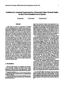
Given a parametrized property graph for query property q we define the centered function q(s(y)) represented by q recursively by: q(s(y)) = Fq (q1 (s(y1 )), . . . , qk (s(yk )). Figure 4: Property graph for nextIndex
at the model level by a query property. Local properties and query properties together make up the set of properties of an EP-system. To decompose the query property, we first describe which values a query property depends on. This is done by defining for each query property a property graph. Definition 12 The property graph for a query property q is defined as follows: the set of nodes is a set of properties that contains property q and other local or query properties. There are three types of edges: local edges, forward edges and inverse edges. A local edge is given by a pair (p1 , p2 ) of properties in the same model. Forward edges and inverse edges are labeled by a property p which we call the link property; for forward properties the link property is a property in the model of p1 whose type is a model containing p2 while for inverse properties it belongs to the model of p2 and its type is a model containing p1 . The link property is a local property or a query property. Intuitively, a local edge represents a dependency of two properties on the same instance while forward and inverse edges represent a dependency between two properties on two separate instances connected by the link property p. At the model level we represent the property graph by adding a parent relation link from a query property to each of its children properties. The parent relation has two attributes: the link property (undefined for local edges) and type (local/forward/inverse). Example 6 Figure 4 shows the property graph for the nextIndex query property nextIndex: this query property computes the index of the next card to be displayed in the quiz dialog. The property graph contains two local edges and one inverse edge (having link property quizDialog). To define the centered function for a query property, we need to assign to the nodes of the property graph functions that compute the value of the property in terms of the values of child properties. Definition 13 A parametrization of a property graph is an assignment of a function to each query property q in the property graph that expresses the query property in terms of the values of child properties q 1 , . . . , qk : q = Fq (q1 , . . . , qk ).
Note that the children properties qi may be query properties or local properties. The instances yi at which qi is evaluated depends on the nature of the child link: if (q, qi ) is a local link then yi = y. If (q, qi ) is a forward edge with link property p, then yi is an instance referred to by y via property p (in s). Lastly if (q, qi ) is an inverse edge with link property p, then yi is an instance that refers to y via property p (in s). At the model level we represent this function by adding a code snippet to each query property that computes the value of the property in terms of the values of children properties. Example 7 The code snippet that computes the value of property nextIndex is given below. Note that it only uses values of properties that are children of itself in the event graph (see figure 4). if (index